

Reelin PNE 13 Seer, PPC 14 Seer Installation Instructions Manual
92-20522-45-03
SUPERSEDES 92-20522-45-02
HEAT PUMP OUTDOOR UNITS:
(-)PNE 13 SEER MODEL SERIES
(-)PPC 14 SEER MODEL SERIES
INSTALLATION INSTRUCTIONS
[ ] INDICATES METRIC CONVERSIONS
!
WARNING
These instructions are intended as an aid to qualified, licensed service personnel for proper installation, adjustment and operation of
this unit. Read these instructions thoroughly before attempting
installation or operation. Failure to follow these instructions may
result in improper installation, adjustment, service or maintenance
possibly resulting in fire, electrical shock, property damage, personal injury or death.
RECOGNIZE THIS SYMBOL AS AN INDICATION OF IMPORTANT SAFETY INFORMATION!
!
!
WARNING
THESE INSTRUCTIONS ARE INTENDED AS AN AID TO
QUALIFIED, LICENSED SERVICE PERSONNEL FOR PROPER
INSTALLATION, ADJUSTMENT AND OPERATION OF THIS UNIT.
READ THESE INSTRUCTIONS THOROUGHLY BEFORE
ATTEMPTING INSTALLATION OR OPERATION. FAILURE TO FOL-
LOW THESE INSTRUCTIONS MAY RESULT IN IMPROPER
INSTALLATION, ADJUSTMENT, SERVICE OR MAINTENANCE
POSSIBLY RESULTING IN FIRE, ELECTRICAL SHOCK,
PROPERTY DAMAGE, PERSONAL INJURY OR DEATH.
DO NOT DESTROY THIS MANUAL
PLEASE READ CAREFULLY AND KEEP IN A SAFE PLACE FOR FUTURE REFERENCE BY A SERVICEMAN

2
TABLE OF CONTENTS
1.0 SAFETY INFORMATION . . . . . . . . . . . . . . . . . . . . . . . . . . . . . . . . . . . . . . . . . . . . 3
2.0 GENERAL INFORMATION . . . . . . . . . . . . . . . . . . . . . . . . . . . . . . . . . . . . . . . . . . 4
2.1 Checking Product Received. . . . . . . . . . . . . . . . . . . . . . . . . . . . . . . . . . . . . . 4
2.2 Application . . . . . . . . . . . . . . . . . . . . . . . . . . . . . . . . . . . . . . . . . . . . . . . . . . . 4
2.3 Dimensions . . . . . . . . . . . . . . . . . . . . . . . . . . . . . . . . . . . . . . . . . . . . . . . . . . 5
2.4 Electrical and Physical Data . . . . . . . . . . . . . . . . . . . . . . . . . . . . . . . . . . . . . 6
3.0 LOCATING UNIT . . . . . . . . . . . . . . . . . . . . . . . . . . . . . . . . . . . . . . . . . . . . . . . . . . 6
3.1 Corrosive Environment . . . . . . . . . . . . . . . . . . . . . . . . . . . . . . . . . . . . . . . . . 6
3.2 Heat Pump Location . . . . . . . . . . . . . . . . . . . . . . . . . . . . . . . . . . . . . . . . . . . 7
3.3 Operational Issues. . . . . . . . . . . . . . . . . . . . . . . . . . . . . . . . . . . . . . . . . . . . . 7
3.4 For Units With Space Limitations. . . . . . . . . . . . . . . . . . . . . . . . . . . . . . . . . . 7
3.5 Customer Satisfaction Issues . . . . . . . . . . . . . . . . . . . . . . . . . . . . . . . . . . . . 8
3.6 Unit Mounting. . . . . . . . . . . . . . . . . . . . . . . . . . . . . . . . . . . . . . . . . . . . . . . . . 8
3.7 Factory-Prepferred Tie-Down Method . . . . . . . . . . . . . . . . . . . . . . . . . . . . . . 8
4.0 REFRIGERANT CONNECTIONS . . . . . . . . . . . . . . . . . . . . . . . . . . . . . . . . . . . . . 9
5.0 REPLACEMENT UNITS. . . . . . . . . . . . . . . . . . . . . . . . . . . . . . . . . . . . . . . . . . . . . 9
6.0 INDOOR COIL . . . . . . . . . . . . . . . . . . . . . . . . . . . . . . . . . . . . . . . . . . . . . . . . . . . 10
6.1 Location . . . . . . . . . . . . . . . . . . . . . . . . . . . . . . . . . . . . . . . . . . . . . . . . . . . . 10
7.0 INTERCONNECTING TUBING . . . . . . . . . . . . . . . . . . . . . . . . . . . . . . . . . . . . . . 10
7.1 Vapor & Liquid Lines . . . . . . . . . . . . . . . . . . . . . . . . . . . . . . . . . . . . . . . . . . 10
7.2 Maximum Length of Lines . . . . . . . . . . . . . . . . . . . . . . . . . . . . . . . . . . . . . . 10
7.3 Outdoor Unit Installed Above Indoor Coil. . . . . . . . . . . . . . . . . . . . . . . . . . . 10
7.4 Outdoor Unit Installed Below Indoor Coil . . . . . . . . . . . . . . . . . . . . . . . . . . 11
7.5 Tubing Installation . . . . . . . . . . . . . . . . . . . . . . . . . . . . . . . . . . . . . . . . . . . . 11
7.6 Tubing Connections. . . . . . . . . . . . . . . . . . . . . . . . . . . . . . . . . . . . . . . . . . . 12
7.7 Leak Testing . . . . . . . . . . . . . . . . . . . . . . . . . . . . . . . . . . . . . . . . . . . . . . . . 12
8.0 DEMAND DEFROST CONTROL . . . . . . . . . . . . . . . . . . . . . . . . . . . . . . . . . . . . . 14
8.1 Defrost Initiation. . . . . . . . . . . . . . . . . . . . . . . . . . . . . . . . . . . . . . . . . . . . . . 14
8.2 Defrost Termination . . . . . . . . . . . . . . . . . . . . . . . . . . . . . . . . . . . . . . . . . . . 14
8.3 Temperature Sensors . . . . . . . . . . . . . . . . . . . . . . . . . . . . . . . . . . . . . . . . . 14
8.4 Test Mode . . . . . . . . . . . . . . . . . . . . . . . . . . . . . . . . . . . . . . . . . . . . . . . . . . 14
8.5 Trouble Shooting Demand Defrost . . . . . . . . . . . . . . . . . . . . . . . . . . . . . . . 14
8.6 High/Low Pressure Control Monitoring - Enhanced Defrost Control Only . . 15
8.7 Enhanced Feature Defrost Control Diagnositc Codes. . . . . . . . . . . . . . . . . 15
9.0 EVACUATION PROCEDURE . . . . . . . . . . . . . . . . . . . . . . . . . . . . . . . . . . . . . . . 15
10.0 START UP & PERFORMANCE . . . . . . . . . . . . . . . . . . . . . . . . . . . . . . . . . . . . . . 16
11.0 CHECKING AIRFLOW . . . . . . . . . . . . . . . . . . . . . . . . . . . . . . . . . . . . . . . . . . . . . 16
12.0 CHECKING REFRIGERANT CHARGE . . . . . . . . . . . . . . . . . . . . . . . . . . . . . . . . 16
12.1 Charging By Liquid Pressure . . . . . . . . . . . . . . . . . . . . . . . . . . . . . . . . . . . . 16
12.2 Charging By Weight . . . . . . . . . . . . . . . . . . . . . . . . . . . . . . . . . . . . . . . . . . . 17
12.3 Final Leak Testing . . . . . . . . . . . . . . . . . . . . . . . . . . . . . . . . . . . . . . . . . . . . 17
13.0 ELECTRICAL WIRING. . . . . . . . . . . . . . . . . . . . . . . . . . . . . . . . . . . . . . . . . . . . . 17
13.1 Power Wiring . . . . . . . . . . . . . . . . . . . . . . . . . . . . . . . . . . . . . . . . . . . . . . . . 17
13.2 Grounding . . . . . . . . . . . . . . . . . . . . . . . . . . . . . . . . . . . . . . . . . . . . . . . . . . 18
13.3 Control Wiring . . . . . . . . . . . . . . . . . . . . . . . . . . . . . . . . . . . . . . . . . . . . . . . 18
14.0 FIELD INSTALLED ACCESSORIES . . . . . . . . . . . . . . . . . . . . . . . . . . . . . . . . . . 18
14.1 Compressor Crankcase Heater . . . . . . . . . . . . . . . . . . . . . . . . . . . . . . . . . . 18
14.2 Hard Start Components . . . . . . . . . . . . . . . . . . . . . . . . . . . . . . . . . . . . . . . . 19
14.3 Time Delay Control (TDC) . . . . . . . . . . . . . . . . . . . . . . . . . . . . . . . . . . . . . . 19
14.4 Low Ambient Control (LAC) . . . . . . . . . . . . . . . . . . . . . . . . . . . . . . . . . . . . . 19
14.5 High Pressure Controls (HPC). . . . . . . . . . . . . . . . . . . . . . . . . . . . . . . . . . . 19
14.6 Enhanced Compressor Protection Kit – RXPG-A01 . . . . . . . . . . . . . . . . . . 19
15.0 TROUBLESHOOTING . . . . . . . . . . . . . . . . . . . . . . . . . . . . . . . . . . . . . . . . . . . . . 20
15.1 Electrical Checks Flow Chart . . . . . . . . . . . . . . . . . . . . . . . . . . . . . . . . . . . . 20
15.2 Cooling Mechanical Checks Flow Chart . . . . . . . . . . . . . . . . . . . . . . . . . . . 21
15.3 Heating Mechanical Checks Flow Chart . . . . . . . . . . . . . . . . . . . . . . . . . . . 22
15.4 Defrost Mechanical Checks Flow Chart. . . . . . . . . . . . . . . . . . . . . . . . . . . . 23
15.5 Subcooling Calculation . . . . . . . . . . . . . . . . . . . . . . . . . . . . . . . . . . . . . . . . 24
15.6 General Troubleshooting Chart . . . . . . . . . . . . . . . . . . . . . . . . . . . . . . . . . . 25
15.7 Service Analyzer Chart . . . . . . . . . . . . . . . . . . . . . . . . . . . . . . . . . . . . . . . . 26
16.0 WIRING DIAGRAMS . . . . . . . . . . . . . . . . . . . . . . . . . . . . . . . . . . . . . . . . . . . . . . 31
3
1.0 SAFETY INFORMATION
!
WARNING
These instructions are intended as an aid to qualified, licensed service personnel for proper installation, adjustment and operation of this unit. Read
these instructions thoroughly before attempting installation or operation.
Failure to follow these instructions may result in improper installation, adjustment, service or maintenance possibly resulting in fire, electrical shock, property damage, personal injury or death.
!
WARNING
The manufacturer’s warranty does not cover any damage or defect to the air
conditioner caused by the attachment or use of any components. Accessories
or devices (other than those authorized by the manufacturer) into, onto or in
conjunction with the air conditioner. You should be aware that the use of
unauthorized components, accessories or devices may adversely affect the
operation of the air conditioner and may also endanger life and property. The
manufacturer disclaims any responsibility for such loss or injury resulting
from the use of such unauthorized components, accessories or devices.
!
WARNING
Disconnect all power to unit before starting maintenance. Failure to do so can
cause electrical shock resulting in severe personal injury or death.
CAUTION
When coil is installed over a finished ceiling and/or living area, it is
recommended that a secondary sheet metal condensate pan be
constructed and installed under entire unit. Failure to do so may result
in property damage.
!
CAUTION
Single-pole contactors are used on all standard single-phase units up through
5 tons. Caution must be exercised when servicing as only one leg of the power
supply is broken with the contactor. Two pole contactors are used on some
three phase units.
!
WARNING
Do not use oxygen to purge lines or pressurize system for leak test. Oxygen
reacts violently with oil, which can cause an explosion resulting in severe personal injury or death.
!
WARNING
Turn off electric power at the fuse box or service panel before making any
electrical connections.
Also, the ground connection must be completed before making line voltage
connections. Failure to do so can result in electrical shock, severe personal
injury or death.
!
WARNING
The unit must be permanently grounded. Failure to do so can cause electrical
shock resulting in severe personal injury or death.
!
CAUTION
Secure elevated unit and elevating stand in order to prevent tipping. Failure to
do this may result in minor or moderate injury.
4
2.0 GENERAL
The information contained in this manual has been prepared to assist in the proper
installation, operation and maintenance of the heat pump equipment. Improper
installation, or installation not made in accordance with these instructions, can result
in unsatisfactory operation and/or dangerous conditions, and can cause the related
warranty not to apply.
Read this manual and any instructions packaged with separate equipment required
to make up the system prior to installation. Retain this manual for future reference.
To achieve optimum efficiency and capacity, the indoor cooling coils listed in the
heat pump specification sheet should be used.
2.1 CHECKING PRODUCT RECEIVED
Upon receiving unit, inspect it for any shipping damage. Claims for damage, either
apparent or concealed, should be filed immediately with the shipping company.
Check heat pump model number, electrical characteristics and accessories to
determine if they are correct. Check system components to make sure they are
properly matched.
2.2 APPLICATION
Before installing any heat pump equipment, a duct analysis of the structure and a
heat gain calculation must be made. A heat gain calculation begins by measuring
all external surfaces and openings that gain heat from the surrounding air and
quantifying that heat gain. A heat gain calculation also calculates the extra heat
load caused by sunlight and by humidity removal.
There are several factors that installers must consider.
• Outdoor unit location • Indoor unit blower speed
• Proper equipment evacuation • Supply and return air duct design and sizing
• Refrigerant charge • System air balancing
• Indoor unit air flow • Diffuser and return air grille location and sizing
!
WARNING
The manufacturer’s warranty does not cover any damage or defect to the
air conditioner caused by the attachment or use of any components.
Accessories or devices (other than those authorized by the manufacturer) into, onto or in conjunction with the air conditioner. You should be
aware that the use of unauthorized components, accessories or devices
may adversely affect the operation of the air conditioner and may also
endanger life and property. The manufacturer disclaims any responsibility
for such loss or injury resulting from the use of such unauthorized components, accessories or devices.
MATCH ALL COMPONENTS:
• OUTDOOR UNIT
• INDOOR COIL/METERING DEVICE
• INDOOR AIR HANDLER/FURNACE
• REFRIGERANT LINES
5
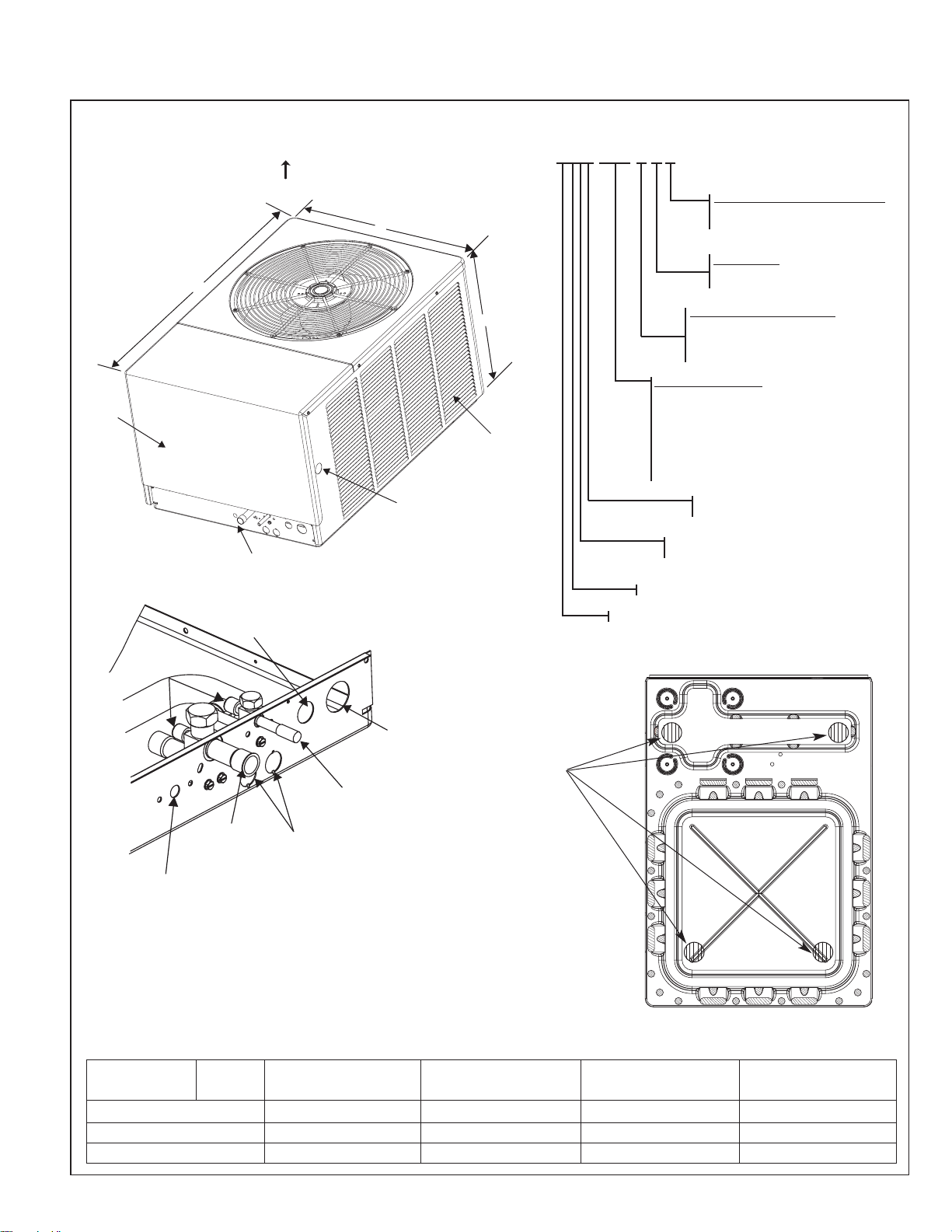
FIGURE 1
DIMENSIONS AND INSTALLATION CLEARANCES
UNIT MODEL NUMBER EXPLANATION
(-)PNE – 036 J A Z
COOLING CONNECTION FITTING
Z - SWEAT WITH SCROLL
Z-COMPRESSOR
VARIATIONS
A - SERIES = FULLY-FEATURED
B - SERIES = COMPETITIVE
ELECTRICAL DESIGNATION
J = 208/230-1-60
C = 208/230-3-60
D = 460-3-60
COOLING CAPACITY
018 = 18,000 BTU/HR
024 = 24,000 BTU/HR
030 = 30,000 BTU/HR
036 = 36,000 BTU/HR
042 = 42,000 BTU/HR
048 = 48,000 BTU/HR
060 = 60,000 BTU/HR
TRADE BRAND
P = REMOTE HEAT PUMP
N = STANDARD EFFICIENCY (13 SEER)
N = (5 TON ONLY)
P = HIGH EFFICIENCY (14 SEER)
C = DESIGN SERIES R-22
E = DESIGN SERIES R-22
DIMENSIONAL DATA
ALTERNATE HIGH VOLTAGE
CONNECTION (KNOCKOUT)
1 11⁄32" [34 mm]
ALLOW 24" [610 mm]
ACCESS CLEARANCE
ACCESS
PANEL
REQUIRED PUMP-UP
INSTALLATION
LOCATIONS
BASE PAN
HEAT PUMP
MODEL
018
19” [482] 19” [482]
29” [736]
44-3/8” [1127]
33” [838]
40-1/2” [1028]
44-3/8” [1127]
44-3/8” [1127]
27-5/8” [701]
31-1/2” [800]
31-1/2” [800] 31-1/2” [800]
024 030
036, 042, 048, 060
(-)PNE/
(-)PPC
HEIGHT “H” (INCHES) [mm]
LENGTH “L” (INCHES) [mm]
WIDTH“W” (INCHES) [mm]
AIR DISCHARGE
ALLOW 60” [1524 mm] CLEARANCE
AIR INLETS
(LOUVERS)
ALLOW 6" [153 mm]
MIN. CLEARANCE
3 SIDES
H
W
2.3 DIMENSIONS (SEE FIGURE 1)
NOTE: SERVICE ACCESS
TO ELECTRICAL & VALVES
ALLOW 24” [610 mm]
CLEARANCE ON SIDE
AIR DISCHARGE
ALLOW 600 [1524 mm] CLEARANCE
L
ACCESS
PANEL
ALLOW 240 [610 mm]
ACCESS CLEARANCE
LOW VOLTAGE
CONNECTION
7
/8" [22 mm]
SERVICE
FITTINGS
W
ALTERNATE HIGH VOLTAGE
CONNECTION (KNOCKOUT)
11
/320 [34 mm]
1
H
AIR INLETS
(LOUVERS)
ALLOW 120 [305 mm]
MIN. CLEARANCE
3 SIDES
A-00002
3
0
0
0
0
-
A
VAPOR LINE
CONNECTION
HIGH PRESSURE
CONTROL
MANUAL RESET
(FIELD INSTALLED
ACCESSORY)
HIGH VOLTAGE
CONNECTION
11
/32" [34 mm]
1
LIQUID LINE
CONNECTION
SERVICE ACCESS
7
/8" [73 mm] DIA.
2
ACCESSORY
KNOCKOUTS
TO ELECTRICAL &
VALVES ALLOW
24" [610 mm]
CLEARANCE
ONE SIDE
BOTTOM VIEW SHOWING DEFROST CONDENSATE
DRAIN OPENINGS (\\\\\\
SHADED AREAS).
6
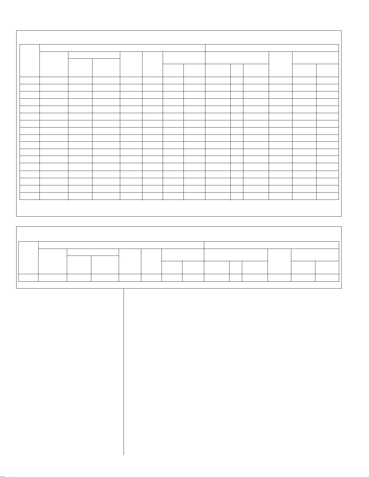
TABLE 1
(-)PNE ELECTRICAL AND PHYSICAL DATA
Model
Number
(-)PNE-
Phase
Frequency
(Hz) Voltage
(Volts)
Rated Load
Amperes
(RLA)
Locked Rotor
Amperes
(LRA)
Fan Motor
Full Load
Amperes
(FLA)
Minimum
Circuit
Ampacity
Amperes
Minimum
Amperes
Maximum
Amperes
Face Area
Sq. Ft. (m
2
)
No.
Rows
CFM [L/s]
Net
Oz. [g]
Shipping
Lbs. [kg]
R22
Oz. [g]
ELECTRICAL
Compressor
Outdoor Coil
Fuse or HACR
Circuit Breaker
Weight
PHYSICAL
018J*Z 1-60-208/2309.0/9.041 0.6 12/12 15/15 20/20 11 [1.02] 1 1925 [908] 74 [2098] 130 [59] 140 [63]
024J*Z 1-60-208/23012.5/12.5 540.8 17/17 20/20 25/25 12.94 [1.2] 1 2475 [1168] 90 [2552] 175 [79.4] 185 [83]
030J*Z 1-60-208/23018.1/18.172.5 0.8 24/24 30/30 40/40 20.13 [1.87] 1 2650 [1251] 129 [3657] 200 [90.
7] 210 [95]
036C*Z 3-60-208/230 42/42 77 0.8 19/19 25/2530/3023.01 [2.14] 1 3000 [1416] 139 [3941] 220 [99.8] 230 [104]
036D*Z 3-60-460 6.9 390.4915 15 23.01 [2.14] 1 3000 [1416] 139 [3941] 220 [99.8] 230 [104]
036J*Z 1-60-208/23020.5/20.5 88 0.8 27/27 35/35 45/45 23.01 [2.14] 1 3000 [1416] 139 [3941] 220 [99.8] 230 [104]
042C*Z 3-60-208/23014.4/14
.488 1.2 20/20 25/2530/3023.01 [2.14] 1 3575 [1687] 146 [4139] 230 [104.3] 240 [108]
042D*Z 3-60-460 7.4440.61015 15 23.01 [2.14] 1 3575 [1687] 146 [4139] 230 [104.3] 240 [108]
042J*Z 1-60-208/23022.7/22.7 104 1.2 30/30 40/40 50/5023.01 [2.14] 1 3575 [1687] 146 [4139] 230 [104.3] 240 [108]
048C*Z 3-60-208/23015.1911.2 20/20 25/2535/35 23.01 [2.14] 1 357
5 [1687] 155 [4394] 250 [113.4] 260 [117]
048D*Z 3-60-460 7.7460.61115 15 23.01 [2.14] 1 3575 [1687] 155 [4394] 250 [113.4] 260 [117]
048J*Z 1-60-208/23023.4/23.41371.2 31/31 40/40 50/5023.01 [2.14] 1 3575 [1687] 155 [4394] 250 [113.4] 260 [117]
048Y*Z➀ 3-60-575 TBD TBD TBD TBD TBD TBD 23.01 [2.14] 1 3575 [1687] 155 [4394] 250 [113.4] 260 [117]
060C*Z 3-60-208/23017
.3/17.3 123 1.223/2330/30 40/40 23.01 [2.14] 2 3350 [1581] 306 [8675] 280 [127] 290 [131]
060D*Z 3-60-460 6.749.5 0.61015 15 23.01 [2.14] 2 3350 [1581] 306 [8675] 280 [127] 290 [131]
060J*Z 1-60-208/23025.0/25.0 148 1.2 33/33 40/40 50/5023.01 [2.14] 2 3350 [1581] 306 [8675] 280 [127] 290 [131]
060Y*Z➀ 3-60-575 TBD TBD TBD TBD TBD TBD 23.01 [2.14] 2 3350 [1581] 306 [8675] 280 [127] 290 [131]
3.0 LOCATING UNIT
3.1 CORROSIVE ENVIRONMENT
The metal parts of this unit may be subject to rust or deterioration if exposed to a
corrosive environment. This oxidation could shorten the equipment’s useful life.
Corrosive elements include, but are not limited to, salt spray, fog or mist in seacoast
areas, sulphur or chlorine from lawn watering systems, and various chemical contaminants from industries such as paper mills and petroleum refineries.
If the unit is to be installed in an area where contaminants are likely to be a problem, special attention should be given to the equipment location and exposure.
• Avoid having lawn sprinkler heads spray directly on the unit cabinet.
• In coastal areas, locate the unit on the side of the building away from the waterfront.
• Shielding provided by a fence or shrubs may give some protection, but cannot
violate minimum airflow and service access clearances.
• Elevating the unit off its slab or base enough to allow air circulation will help
avoid holding water against the basepan.
Regular maintenance will reduce the build-up of contaminants and help to protect
the unit’s finish.
2.4 ELECTRICAL & PHYSICAL DATA (SEE TABLE 1 & 2)
➀ Electrical Data is not available at this time
TABLE 2
(-)PPC ELECTRICAL AND PHYSICAL DATA
Model
Number
(-)PPC-
Phase
Frequency
(Hz) Voltage
(Volts)
Rated Load
Amperes
(RLA)
Locked Rotor
Amperes
(LRA)
Fan Motor
Full Load
Amperes
(FLA)
Minimum
Circuit
Ampacity
Amperes
Minimum
Amperes
Maximum
Amperes
Face Area
Sq. Ft. (m
2
)
No.
Rows
CFM [L/s]
Net
Lbs. [kg]
Shipping
Lbs. [kg]
Refrig.
Per
Circuit
Oz. [g]
ELECTRICAL
Compressor
Outdoor Coil
Fuse or HACR
Circuit Breaker
Weight
PHYSICAL
060JAZ 1-60-208-23025/25 148 1.2 33/33 40/40 50/5023.01 [2.14] 2 3350 [1581] 295 [8363]255 [115.7] 265 [120.2]
• Frequent washing of the cabinet, fan blade and coil with fresh water will remove
most of the salt or other contaminants that build up on the unit.
• Regular cleaning and waxing of the cabinet with an automobile polish will provide some protection.
• A liquid cleaner may be used several times a year to remove matter that will not
wash off with water.
Several different types of protective coil coatings are offered in some areas. These
coatings may provide some benefit, but the effectiveness of such coating materials
cannot be verified by the equipment manufacturer.
3.2 HEAT PUMP LOCATION
Consult local and national building codes and ordinances for special installation
requirements. Following location information will provide longer life and simplified
servicing of the outdoor heat pump.
NOTE: These units must be installed outdoors. No ductwork can be attached, or
other modifications made, to the discharge grille. Modifications will affect performance or operation.
3.3 OPERATIONAL ISSUES
• IMPORTANT: Locate the unit in a manner that will not prevent, impair or compromise the performance of other equipment horizontally installed in proximity
to the unit. Maintain all required minimum distances to gas and electric meters,
dryer vents, exhaust and inlet openings. In the absence of National Codes, or
manaufacturers’ recommendations, local code recommendations and requirements will take presidence.
• Refrigerant piping and wiring should be properly sized and kept as short as
possible to avoid capacity losses and increased operating costs.
• Locate the unit where water run off will not create a problem with the equipment. Position the unit away from the drip edge of the roof whenever possible.
Units are weatherized, but can be affected by the following:
o Water from the junction of rooflines, without protective guttering, entering the
heat pump while in operation, can impact fan blade or motor life. Coil damage may occur to a heat pump if moisture cannot drain from the unit under
freezing conditions.
o Freezing moisture, or sleeting conditions, can cause the cabinet to ice-over
prematurely and prevent heat pump operation, requiring backup heat, which
generally results in less economical operation.
• Closely follow clearance recommendations (see Figure 1).
o 24” to the service panel access
o 60” above heat pump fan discharge (unit top) to prevent recirculation
o 6” to heat pump coil grille air inlets (per heat pump).
3.4 FOR UNITS WITH SPACE LIMITATIONS
In the event that a space limitation exists, we will permit the following clearances:
Single Unit Applications: Heat pump grille side clearances below 6 inches will
reduce unit capacity and efficiency. Do not reduce the 60-inch discharge, or the 24inch service clearances.
Multiple Unit Applications: When multiple heat pump grille sides are aligned, a 6inch per unit clearance is recommended, for a total of 12 inches between multiple
units. Two combined clearances below 12 inches will reduce capacity and efficiency. Do not reduce the 60-inch discharge, or 24-inch service clearances.
• Do not obstruct the bottom drain opening in the heat pump base pan. It is
essential to provide defrost condensate drainage to prevent possible refreezing
of the condensation. Provide a base pad for mounting the unit, which is slightly
pitched away from the structure. Route condensate off the base pad to an area
which will not become slippery and result in personal injury.
7
!
WARNING
Disconnect all power to unit before starting maintenance. Failure to do so
can cause electrical shock resulting in severe personal injury or death.
8
• Where snowfall is anticipated, the heat pump must be elevated above the base
pad to prevent ice buildup that may crush the tubing of the heat pump coil or
cause fin damage. Heat pump units should be mounted above the average
expected accumulated snowfall for the area.
3.5 CUSTOMER SATISFACTION ISSUES
• The heat pump should be located away from the living, sleeping and recreational spaces of the owner and those spaces on adjoining property.
• To prevent noise transmission, the mounting pad for the outdoor unit should
not be connected to the structure, and should be located sufficient distance
above grade to prevent ground water from entering the unit.
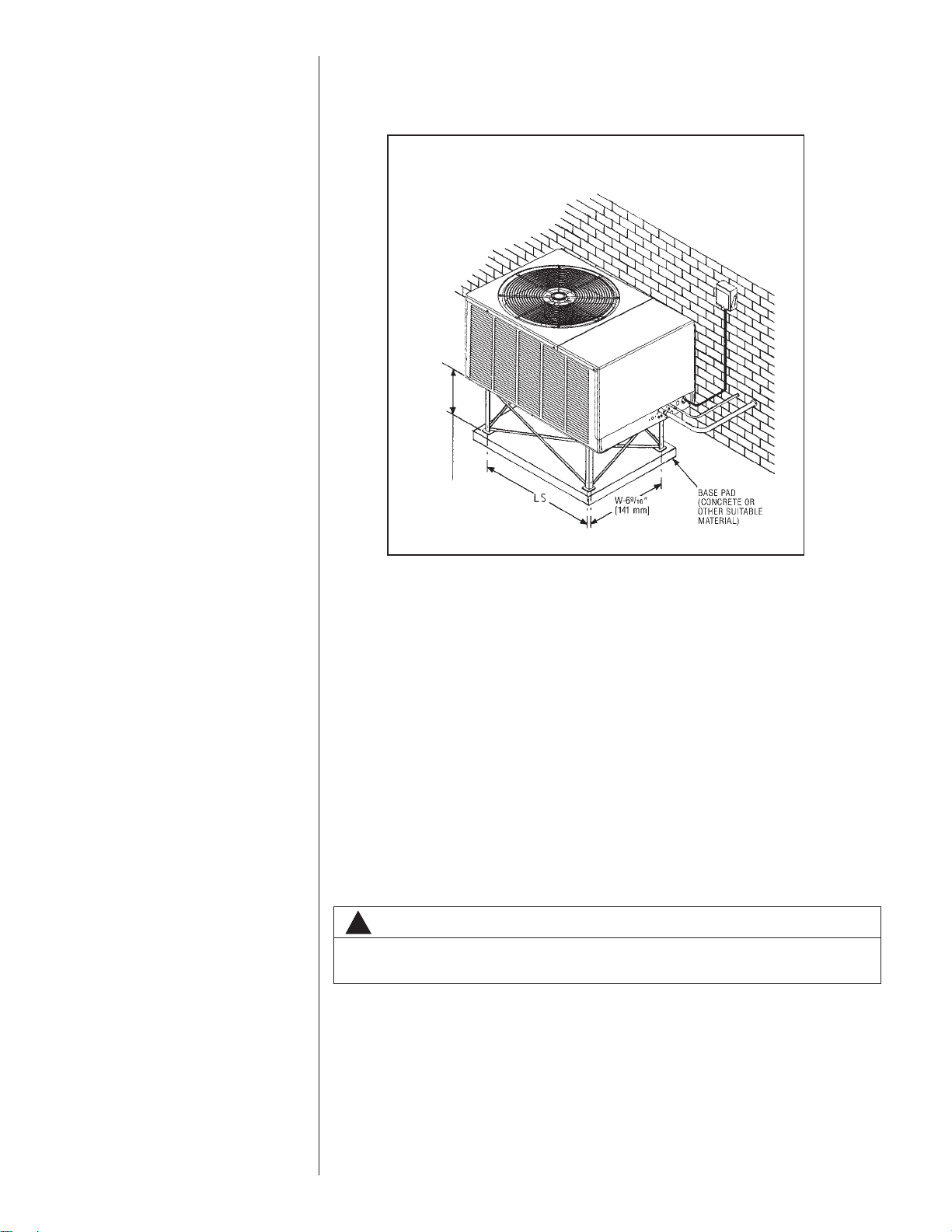
3.6 UNIT MOUNTING
If elevating the heat pump, either on a flat roof or on a slab, observe the
following guidelines. (See Figure 2.)
• The base pan provided elevates the heat pump 3/4” above the base pad.
• If elevating a unit on a flat roof, use 4” x 4” (or equivalent) stringers positioned
to distribute unit weight evenly and prevent noise and vibration.
NOTE: Do not block drain openings shown in Figure 1.
• If unit must be elevated because of anticipated snow fall, secure unit and elevating stand such that unit and/or stand will not tip over or fall off.
3.7 FACTORY-PREFERRED TIE-DOWN METHOD
INSTRUCTIONS
IMPORTANT: These instructions are intended as a guide to securing equipment for
wind-load ratings of “120 MPH sustained wind load” and “3-second, 150 MPH gust.”
While this procedure is not mandatory, the Manufacturer does recommend that
equipment be properly secured in areas where high wind damage may occur.
STEP 1: Before installing, clear pad of any dirt or debris.
IMPORTANT: The pad must be constructed of industry-approved materials,
and must be thick enough to accommodate the concrete fastener.
FIGURE 2
RECOMMENDED ELEVATED INSTALLATION
!
CAUTION
Secure elevated unit and elevating stand in order to prevent tipping.
Failure to do this may result in minor or moderate injury.
ELEVATION ABOVE
ANTICIPATED SNOW’FALL IS NECESSARY.
DO NOT BLOCK
OPENINGS IN BASE
PAN. REFER TO
FIGURE 1.
STEP 2: Center base pan on pad, ensuring it is level.
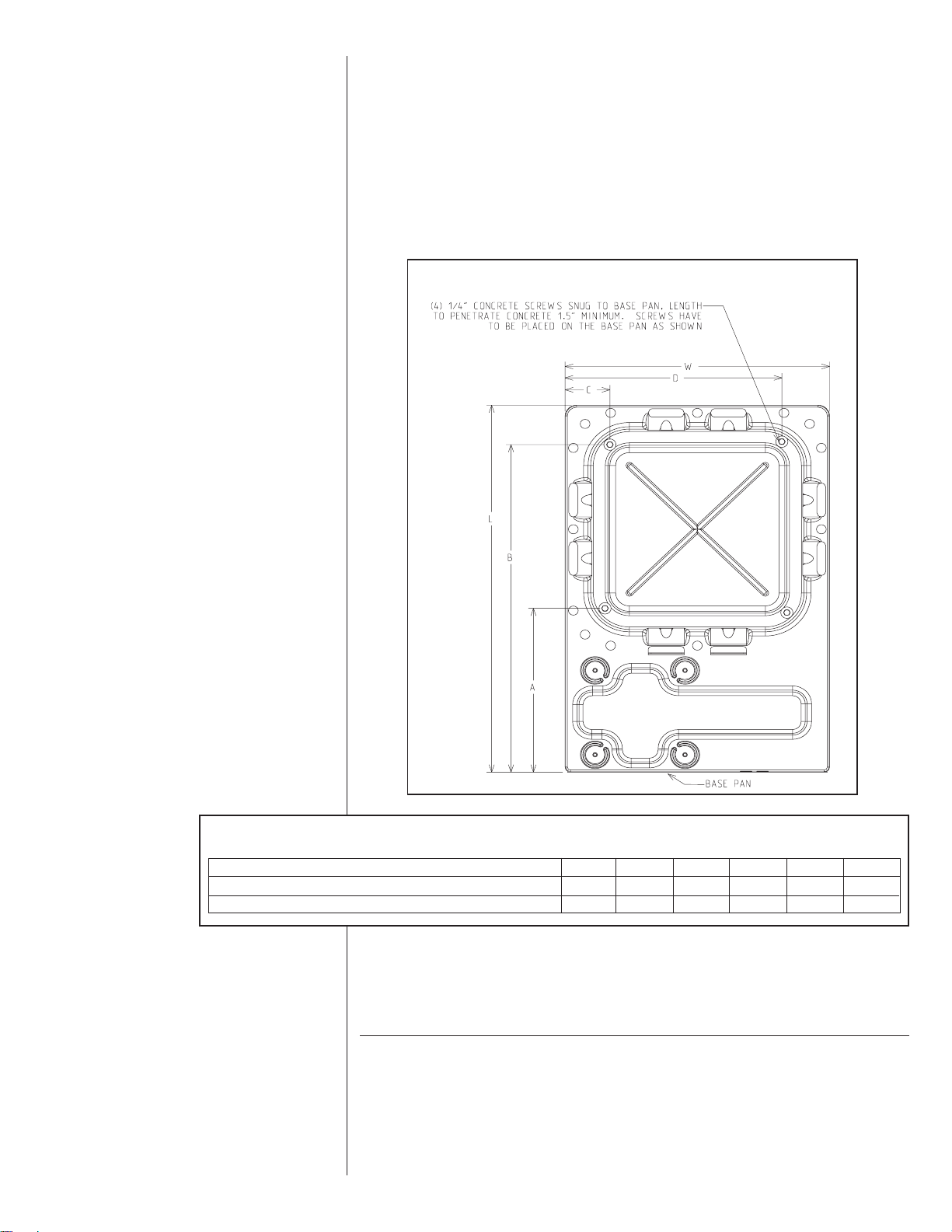
STEP 3: Using basepad as a guide, mark spots on concrete where 4 holes will be
drilled (see Figure 3).
STEP 4: Drill four pilot holes in pad, ensuring that the hole is at least 1/4” deeper
than the concrete screw being used.
STEP 5: Center basepan over pre-drilled holes and insert concrete screws.
STEP 6: Tighten concrete screws.
NOTE: Do not over-tighten the concrete screws. Doing so can weaken the
integrity of the concrete screw and cause it to break.
STEP 7: Finish unit assembly per unit’s installation instructions.
4.0 REFRIGERANT CONNECTIONS
All units are factory charged with Refrigerant 22. All models are supplied with service valves. Keep tube ends sealed until connection is to be made to prevent system contamination.
5.0 REPLACEMENT UNITS
To prevent failure of a new heat pump unit, the existing tubing system must be correctly sized and cleaned or replaced. Care must be exercised that the expansion
device is not plugged. For new and replacement units, a liquid line filter drier should
be installed and refrigerant tubing should be properly sized. Test the oil for acid. If
positive, a liquid line filter drier is mandatory.
9
FIGURE 3
SCREW LOCATIONS ON BASEPAN
TABLE 3
BASEPAN DIMENSIONS
MODEL NUMBER L W A B C D
(-)PNE/(-)PPC-018 37.625” 25.938” 15” 34” 3.5” 22.5”
(-)PNE/(-)PPC-024/030/036/042/048/060 41.5” 29.813” 15” 38” 3.5” 26.5”
10
6.0 INDOOR COIL
REFER TO INDOOR COIL MANUFACTURER’S INSTALLATION INSTRUCTIONS.
IMPORTANT: The manufacturer is not responsible for the performance and opera-
tion of a mismatched system, or for a match listed with another manufacturer’s coil.
6.1 LOCATION
Do not install the indoor coil in the return duct system of a gas or oil furnace.
Provide a service inlet to the coil for inspection and cleaning. Keep the coil pitched
toward the drain connection.
7.0 INTERCONNECTING TUBING
7.1 VAPOR AND LIQUID LINES
Keep all lines sealed until connection is made.
Make connections at the indoor coil first.
Refer to Line Size Information in Tables 3 through 5 for correct size and multipliers to
be used to determine capacity for various vapor line diameters and lengths of run.
The losses due to the lines being exposed to outdoor conditions are not included.
The factory refrigeration charge in the outdoor unit is sufficient for 15 feet of interconnecting lines. The factory refrigeration charge in the outdoor unit is sufficient for
the unit and 15 feet of standard size interconnecting liquid and vapor lines. For different lengths, adjust the charge as indicated below.
1/4” ± .3 oz. per foot
5/16” ± .4 oz. per foot
3/8” ± .6 oz. per foot
1/2” ± 1.2 oz. per foot
7.2 MAXIMUM LENGTH OF LINES
The maximum length of interconnecting line is 150 feet. Always use the shortest
length possible with a minimum number of bends. Additional compressor oil is not
required for any length up to 150 feet.
NOTE: Excessively long refrigerant lines cause loss of equipment capacity.
7.3 OUTDOOR UNIT INSTALLED ABOVE INDOOR COIL
Keep the vertical separation between coils to a minimum. However, the vertical distance can be as great as 120 feet with the condensing unit ABOVE the indoor coil.
Use the following guidelines when installing the unit:
1. DO NOT exceed 120 feet maximum vertical separation.
2. DO NOT change the flow check piston sizes if the vertical separation does not
exceed the values in Table 4.
3. Flow Check Piston Coil:
a. The vertical separation can be greater than the value in Table 4, but no
more than 120 feet.
b. If the separation height exceeds the Table value, reduce the indoor coil flow
check piston by two sizes plus one size for additional 10 feet beyond the
Table value.
CAUTION
When coil is installed over a finished ceiling and/or living area, it is
recommended that a secondary sheet metal condensate pan be
constructed and installed under entire unit. Failure to do so may result
in property damage.

11
4. Expansion Valve Coil:
a. The vertical separation can be greater than the Table value, but no more
than 120 feet.
b. No changes are required for expansion valve coils.
5. Capillary Tube Coil:
DO NOT exceed the Table values for vertical separation for capillary tube coils.
6. Always use the smallest liquid line size permitted to minimize the system
charge.
7. Table 4 may be used for sizing horizontal runs.
7.4 OUTDOOR UNIT BELOW INDOOR COIL
Keep the vertical separation to a minimum. Use the following guidelines when
installing the unit:
1. DO NOT exceed the vertical separations as indicated on Table 5.
2. Always use the smallest liquid line size permitted to minimize system charge.
3. No changes are required for either flow check piston coils or expansions coils.
4. Table 5 may be used for sizing horizontal runs.
7.5 TUBING INSTALLATION
Observe the following when installing correctly sized type “L” refrigerant tubing
between the condensing unit and evaporator coil:
• If a portion of the liquid line passes through a hot area where liquid refrigerant
can be heated to form vapor, insulating the liquid line is required.
• Use clean, dehydrated, sealed refrigeration grade tubing.
• Always keep tubing sealed until tubing is in place and connections are to be
made.
• Blow out the liquid and vapor lines with dry nitrogen before connecting to the
outdoor unit and indoor coil. Any debris in the line set will end up plugging the
expansion device.
• As an added precaution, a high quality, bi-directional filter drier is recommend-
ed to be installed in the liquid line, if not factory installed.
• Do not allow the vapor line and liquid line to be in contact with each other. This
causes an undesirable heat transfer resulting in capacity loss and increased
power consumption. The vapor line must be insulated.
• If tubing has been cut, make sure ends are deburred while holding in a position
to prevent chips from falling into tubing. Burrs such as those caused by tubing
cutters can affect performance dramatically, particularly on small liquid line
sizes.
• For best operation, keep tubing run as short as possible with a minimum num-
ber of elbows or bends.
• Locations where the tubing will be exposed to mechanical damage should be
avoided. If it is necessary to use such locations, the copper tubing should be
housed to prevent damage.
• If tubing is to be run underground, it must be run in a sealed watertight chase.
• Use care in routing tubing and do not kink or twist. Use a good tubing bender
on the vapor line to prevent kinking.
• Route the tubing using temporary hangers, then straighten the tubing and
install permanent hangers. Line must be adequately supported.
• The vapor line must be insulated to prevent dripping (sweating) and prevent
performance losses. Armaflex and Rubatex are satisfactory insulations for this
purpose. Use 1/2” minimum insulation thickness, additional insulation may be
required for long runs.
• Check Table 3 for the correct vapor line size. Check Tables 4 and 5 for the cor-
rect liquid line size.
 Loading...