

Page 1
Operating Instructions
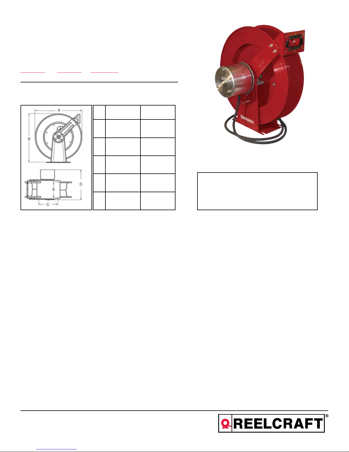
Series WC80000 Welding Cable Reels
Model Numbers:
WC80001 WC80002 WCH80001
Dimensions
WC WCH
A 24” 24”
B 25 3/8” 25 3/8”
C 10” 10”
D 16” 15”
E 6” 6”
Four 1/2” diameter mounting holes
SAFETY
Personal injury and/or equipment damage may result if proper safety
precautions are not observed.
• Ensure that only a qualified electrician installs/services this
equipment.
• Ensure that power supply voltage does not exceed maximum
voltage rating of reel.
• Ensure that reel is properly installed before connecting to power
supply.
• Ensure that all electrical power is removed from reel before servicing.
• Check for frayed/broken wires before each use.
IMPORTANT
Read this manual carefully before installing,
operating or servicing this equipment.
• Ensure that reel, electrical cable, and equipment being serviced
are properly grounded. Use an ohmmeter to check ground
continuity.
• If reel ceases to unwind or rewind, remove power immediately.
Do not pull or jerk on electrical cable!
• Treat and respect the cable reel as any other piece of machinery,
observing all common safety practices.
WARNING: Even low voltage can cause irreparable damage or
death! Exercise extreme caution while operating or servicing this
equipment.
• Pull electrical cord from reel by grasping the electrical cord itself,
not the work device.
• If an electrical malfunction should occur, remove power from reel
immediately.
Reelcraft Industries, Inc. • 2842 E Business Hwy 30, Columbia City, IN 46725
Ph: 800-444-3134 / 260-248-8188 • Fax: 800-444-4587 / 260-248-2605
Customer Service: 855-634-9109 • reelcraft@reelcraft.com • www.reelcraft.com
WARNING: This reel is to be used for cable storage only! The
entire length of cable must be unwound before use. Severe damage to the reel will result if the cable is energized while fully
wound on the reel.
Form# 1155-304 Rev: 10/2018
Page 2
Series WC80000 Welding Cable Reels
INSTALLATION INSTRUCTIONS
Ensure that only a qualified electrician installs/service this equiment.
Observe applicable NEC, OSHA, and local codes when installing this
equipment.
MOUNTING
Caution: Unless reel was specified differently when ordering, maxi-
mum installation height is 16 feet. Do not exceed this distance.
1. Unpack and inspect reel for damage. Turn by hand to check for
smooth operation. Check for completeness.
2. Configure reel for top, side or bottom hose dispensing by remov-
ing the bolts (1) from one side of the guide roller bracket and
loosening the four guide arm bolts (2) on each side of the cable
reel. Rotate and remove each guide arm then reinstall in the
desired configuration.
3. Position reel on floor, wall, or ceiling. Secure into place using four
(customer supplied) bolts.
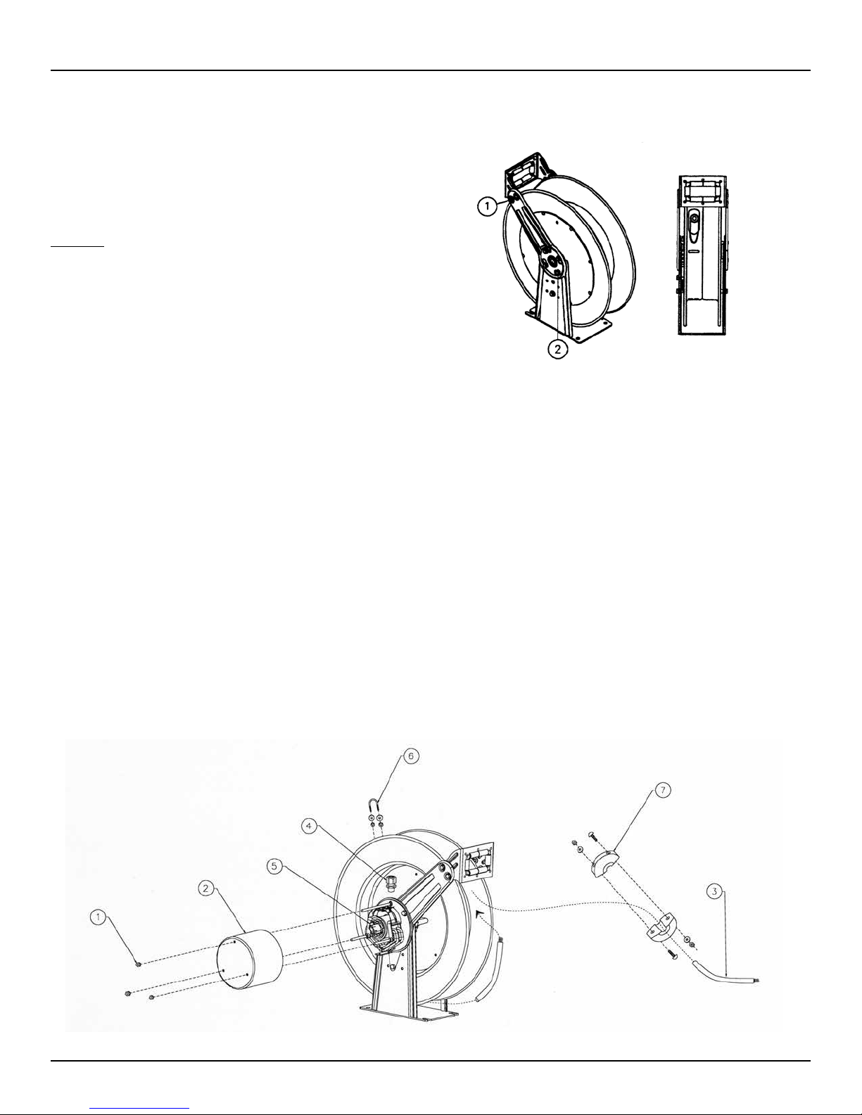
INSTALLING THE OUTPUT CABLE
1. Remove the three outer nuts (1) on the collector ring cover, and remove the cover (2).
2. Strip 1 1/8” of installation from the output cable (3), and insert the cable around the reel spool (not through the guide arm open-
ing).
3. Add protective tubing around opening in spool. Next route the output cable through the opening in the spool, through the strain
relief (4), through the mainshaft, and then capture cable at end of collector ring with set-screw (5). Fasten the strain relief to the
mainshaft and then tighten the cable with the strain relief.
4. Replace the collector ring cover (2) and secure with three outer nuts (1).
5. Fasten cable to spool by capturing with u-bolt (6) and then tightening to spool with washers and nuts.
6. Wrap all of the output cable around the spool.
7. Once cable is wound on the spool add additional turns (2-3 should be sufficient) to add tension to cable.
8. Add bumper (7) to cable at desired location.
9. Using an ohmmeter, check for ground faults.
Page 2
www.reelcraft.com
Page 3

Series WC80000 Welding Cable Reels
Item
#
1 Machine Screw 7 S44-10 S44-10 S44-10
2 Guide Arm 2 261299 261299 261299
3 3/8-16 x 5/8” Machine Screw 9 S44-2 S44-2 S44-2
4 Snap Ring 2 S140-34 S140-34 S140-34
5 Bearing & Flange Assembly 1 S600644 S600644 S600644
6 Spring & Case Assembly 1 S600653-3 S600645-2 S600653-3
7 Latch Pawl Assembly 1 S600675 S600675 S600675
8 Nyloc Nut ** 2 S85-7 S85-7 -----8 Nyloc Nut 1 S85-7 S85-7 S85-7
8A 10-32 Nyloc Nut 1 S82-15 S82-15 S82-15
9 Latch Spring 1 S260067 S260067 260067-1
10 Base & Upright Assembly 1 600641 600641 600641
11 Spacer 1 390030-12 390030-12 390030-12
12 Mounting Plate 1 261809 261809 261809
13 1/4-20 x 2 1/2” Screw 1 S2-511 S2-511 S376-59
14 Grommet 2 261817 261817 261817
15 Hex Flange Nut 1 S280-8 S280-8 S280-8
16 Sheave Assembly 1 600649 600649 600649
17 Flange with Nut Sert 1 S600651 S600651 S600651
18 Main Shaft 1 261808 261808 261808
19 Collector Ring Assembly 1 600987 600987 602687
20 Welding Cable Shaft 1 261812 261812 262933
21 Cord Grip Assembly 1 261555 261555 262916
22 1/4-20 Nyloc Nut 2 261650-1 261650-1 261650-1
24 U-bolt 1 3-117440 3-117440 3-117440
25 Roller Bracket Assembly 1 S600642 S600642 S600642
26 Lock Nut 4 300107 300107 300107
Description
#
WC80001 WC80002 WCH80001
Req.
www.reelcraft.com
**Prior to March 2012
Page 3
 Loading...