

Page 1
Operating Instructions
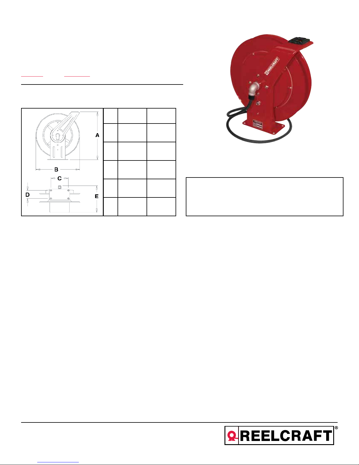
Series WC7000 Welding Cable Reels
Model Numbers:
WC7000 WCH7000
Dimensions
WC7000 WCH7000
A 20 1/4” 20 1/4”
B 19 3/4” 19 3/4”
C 7 7/8” 7 7/8”
D 3 7/8” 3 7/8”
E 13 1/4” 14”
Four 1/2” diameter mounting holes
SAFETY
Personal injury and/or equipment damage may result if proper safety
precautions are not observed.
• Ensure that only a qualified electrician installs/services this
equipment.
• Ensure that power supply voltage does not exceed maximum
voltage rating of reel.
• Ensure that reel is properly installed before connecting to power
supply.
• Ensure that all electrical power is removed from reel before servicing.
• Check for frayed/broken wires before each use.
IMPORTANT
Read this manual carefully before installing, operating or
servicing this equipment.
• Ensure that reel, electrical cable, and equipment being serviced
are properly grounded. Use an ohmmeter to check ground
continuity.
• If reel ceases to unwind or rewind, remove power immediately.
Do not pull or jerk on electrical cable!
• Treat and respect the cable reel as any other piece of machinery,
observing all common safety practices.
WARNING: Even low voltage can cause irreparable damage or
death! Exercise extreme caution while operating or servicing this
equipment.
• Pull electrical cord from reel by grasping the electrical cord
itself, not the work device.
• If an electrical malfunction should occur, remove power from reel
immediately.
Reelcraft Industries, Inc. • 2842 E Business Hwy 30, Columbia City, IN 46725
Ph: 800-444-3134 / 260-248-8188 • Fax: 800-444-4587 / 260-248-2605
Customer Service: 855-634-9109 • reelcraft@reelcraft.com • www.reelcraft.com
WARNING: This reel is to be used for cable storage only! The
entire length of cable must be unwound before use. Severe damage to the reel will result if the cable is energized while fully
wound on the reel.
Form# 1154-304 Rev: 10/2018
Page 2
Series WC7000 Welding Cable Reels
INSTALLATION INSTRUCTIONS
Ensure that only a qualified electrician installs/service this equiment.
Observe applicable NEC, OSHA, and local codes when installing this
equipment.
MOUNTING
Caution: Unless reel was specified differently when ordering, maxi-
mum installation height is 16 feet. Do not exceed this distance.
1. Unpack and inspect reel for damage. Turn by hand to check for
smooth operation. Check for completeness.
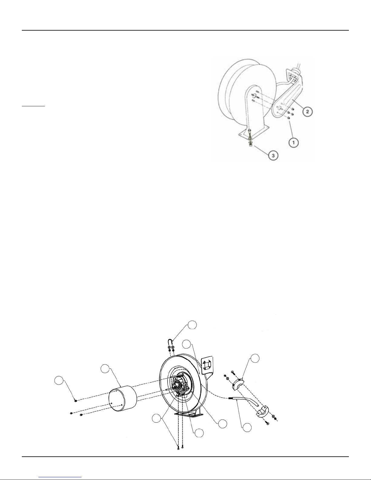
2. Configure reel for top, side or bottom hose dispensing by removing the bolts (1) from one side of the guide arm bracket (2).
Position guide arm bracket to desired location and replace nuts.
3. Position reel on floor, wall, or ceiling. Secure into place using four
(customer supplied) bolts (3).
INSTALLING THE OUTPUT CABLE
1. Remove the three outer nuts (1) on the collector ring cover, and remove the cover (2).
2. Strip 1 1/8” of insulation from the output cable (3), and insert the cable around the reel spool (not through the guide arm opening).
3. Add protective tubing around opening in spool. Next route the input cable through the opening in the spool, through the opening
in the collector ring base casting (4), then through the strain relief (5).
4. Continue threading cable until stripped end of cable is between the 2 clamp plates (6), tighten nuts/screws of the clamp plates
until the cable is securely captured between the plates.
5. Tighten the strain relief (5). Replace collector ring cover (2) and secure with three outer nuts (1).
6. Fasten cable to spool by capturing with u-bolt (7) and then tightening to spool with nuts.
7. Using an ohmmeter, check for ground faults.
8. Wind cable onto spool by squeezing through gap between spool and guide arm (8).
9. Once cable is wound on the spool add additional turns (2-3 should be sufficient) to add tension to cable.
10. Add bumper (9) to cable at desired location.
7
8
9
2
1
Page 2
6
4
5
3
www.reelcraft.com
Page 3

Series WC7000 Welding Cable Reels
Item
#
1 Collector Ring Assembly 1 600983 602723 15 Elbow 1 261816 263050
2 Sheave Assembly 1 S600951 S600951 16 Cord Grip 1 261555 262916
3 5/16-18 x 3” Machine Screw 1 S329-520 S329-520 21 10-32 x 3/8” Nyloc Nut 1 S82-15 S82-15
4 Spring Case Gasket 1 S260069 S260069 22 1/2-20 x 5/8” Hex Nut 1 S280-8 S280-8
5 Drive Spring Assembly 1 S260053 S260053 23 Latch Spring 1 S260067 S260067
6 Spring Case Stud 1 S260031 S260031 24 10-32 Shoulder Screw 1 S393-2 S393-2
7 Spring Case & Ratchet Assembly 1 S260074 S260074 25 Latch Pawl Assembly 1 S600018 S600018
8 3/8-24 Jam Nut 1 S76-106 S76-106 26 Main Shaft 1 261174 261174
9 10-32 Hex Locknut 6 S300011 S300011 27 Spring Arbor & Key Assembly 1 S600621 S600621
10 Snap Ring 2 300007 300007 28 Grommet 1 261824 -------11 Base Assembly 1 S600016 S600016 29 U-Bolt 1 3-117440 3-117440
12 1/2-13 Set Screw 1 S35-84 S35-84 30 1/4-20 x 3/8” Locknut 2 261650-1 261650-1
13 Guide Arm Assembly 1 S600017 S600017 --- Inlet Cord Assembly 1 261603 262930
14 5/16-18 Locknut 4 300107 300107
Description
#
WC7000 WCH7000
Req.
Item
#
Description
#
WC7000 WCH7000
Req.
www.reelcraft.com
Page 3
Page 4

Instrucciones de Operacion
Serie WC7000 Carretes para Cable de Soldadura
Número de modelo:
WC7000 WCH7000
Datos Dimensionales
WC7000 WCH7000
A 20 1/4” 20 1/4”
B 19 3/4” 19 3/4”
C 7 7/8” 7 7/8”
D 3 7/8” 3 7/8”
E 13 1/4” 14”
Four 1/2” diameter mounting holes
SEGURIDAD
Es posible que ocurran lesiones personales y/o daños al equipo si
no se siguen las precauciones de seguridad apropiadas.
• Cerciórese de que únicamente un electricista certificado instale
o proporcione servicio a este equipo.
•
• Cerciórese de que el voltaje de la fuente de energía no exceda
de la clasificación de voltaje máxima del carrete.
•
• Cerciórese de que el carrete esté debidamente instalado antes
de conectarlo a la fuente de energía.
•
• Antes de dar servicio al carrete, cerciórese de desconectar la
energía eléctrica.
•
• Verifique que no haya cables deshilados o rotos antes de cada
uso.
•
• Jale el cable eléctrico del carrete tirando del cable mismo, no
del dispositivo de trabajo.
•
• En caso de que ocurra alguna falla eléctrica, desconecte el
carrete de inmediato de la fuente de energía.
•
•
•
IMPORTANTE
Lea este manual detenidamente antes de instalar, operar o
dar servicio a este equipo.
• Cerciórese de que al dar servicio a los carretes, los cables
eléctricos y los equipos, éstos estén debidamente puestos a
tierra. Utilice un ohmiómetro para verificar la continuidad de la
tierra física.
• Si no es posible desenrollar o rebobinar el carrete, desconecte
de inmediato la fuente de energía. No jale ni tire del cable
eléctrico. Respete el carrete para manguera y trátelo como
cualquier pieza de maquinaria, siguiendo todas las.
ADVERTENCIA: ¡Recuerde que incluso las presiones bajas pueden
causar daños irreparables e incluso la muerte! Tenga mucho cuidado al operar o dar servicio a este equipo.
WARNING: ¡Este carrete únicamente debe ser utilizado para
almacenar cable! Es necesario desenrollar toda la longitud d el
cable antes de utilizarlo. Si el cable es energizado mientras se
encuentra totalmente embobinado, esto resultará en daños severos
al carrete.
Form# 1154-304 Rev: 10/2018
Reelcraft Industries, Inc. • 2842 E Business Hwy 30, Columbia City, IN 46725
Ph: 800-444-3134 / 260-248-8188 • Fax: 800-444-4587 / 260-248-2605
Customer Service: 855-634-9109 • reelcraft@reelcraft.com • www.reelcraft.com
Page 5

Serie WC7000 Carretes para Cable de Soldadura
INSTRUCCIONES DE INSTALACION
Cerciórese de que únicamente un electricista calificado instale o proporcione servicio al equipo. Cumpla con los códigos NEC, OSHA y
demás códigos eléctricos locales al instalar el equipo.
MONTAJE DEL CARRETE PARA CABLE
PRECAUCION : A menos de que se haya especificado de manera
distinta al ordenar el carrete, la altura máxima de instalación es de 16
pies. No exceda de esta distancia.
1. Desempaque el carrete e inspecciónelo para determinar si presenta
daños. Gírelo manualmente para verificar si la operación es uniforme. Verifique que todo esté completo.
2. Configure el carrete para un suministro superior, lateral o inferior
de la manguera retirando los pernos (1) que aseguran la ménsula
del brazo guía (2). Coloque la ménsula del brazo guía en la ubicación deseada y vuelva a colocar las tuercas.
3. Coloque el carrete en el piso, en la pared o en el techo. Fíjelo en
su sitio utilizando cuatro pernos (provistos por el cliente) (3).
Instalacion del Cable de Salida
1. Retire las tres tuercas exteriores (1) en la cubierta del anillo colector y retire la cubierta (2).
2. Retire una sección de 1 1/8” del aislamiento del cable de salida (3) e inserte el cable alrededor de la bobina del carrete (no lo
inserte a través de la abertura del brazo guía).
3. Coloque el tubo de protección alrededor de la abertura de la bobina. A continuación, enrute el cable de salida a través de la
abertura de la bobina, luego a través de la abertura en la pieza fundida de la base del anillo colector (4) y finalmente a través del
aliviador de tensión (5).
4. Continúe insertando el cable hasta que el extremo pelado del cable se encuentre entre las 2 placas de sujeción (6) y apriete las
tuercas y los tornillos de las placas de sujeción hasta que el cable quede atrapado firmemente entre las placas.
5. Apriete el liberador de tensión (5). Vuelva a colocar la cubierta del anillo colector (2) y fíjela utilizando tres tuercas exteriores (1).
6. Fije el cable a la bobina atrapándolo con el perno en U (7) y luego apretándolo hacia la bobina con las tuercas y las arandelas.
7. Utilice un ohmiómetro para verificar si existen fugas a tierra.
8. Rebobine el cable sobre la bobina insertándolo a través del espacio entre la bobina y el brazo guía (8).
9. Una vez que el cable haya sido embobinado sobre la bobina, gire la manivela 2 ó 3 vueltas adicionales para tensionar el cable.
10. Agregue un tope (9) al cable en la ubicación deseada.
7
8
9
2
1
www.reelcraft.com
6
4
5
3
Page 5
Page 6

Serie WC7000 Carretes para Cable de Soldadura
ART.
NO.
1 Conjunto de anillo colector 1 600983 602723 15 Codo 1 261816 263050
2 Conjunto de roldana 1 S600951 S600951 16 Agarre del cable 1 261555 262916
Tornillo para metales, 5/16-18 x 3”
3
4 Junta de la caja de resorte 1 S260069 S260069 22 Tuerca hexagonal, 1/2-20 x 5/8” 1 S280-8 S280-8
5 Conjunto de resorte de accionamiento 1 S260053 S260053 23 Resorte de enganche 1 S260067 S260067
6 Perno de la caja de resorte 1 S260031 S260031 24 10-32 tornillo de hombro 1 S393-2 S393-2
7 Conjunto de caja de resorte y trinquete 1 S260074 S260074 25 Conjunto de dedo de enganche 1 S600018 S600018
8 Contratuerca, 3/8-24 1 S76-106 S76-106 26 Eje principal 1 261174 261174
9 Contratuerca hexagonal, 10-32 6 S300011 S300011 27 Conjunto de eje de resorte y chaveta 1 S600621 S600621
10 Anillo de retención 2 300007 300007 28 Arandela aislante 1 261824 -------11 Conjunto de base 1 S600016 S600016 29 Perno en U 1 3-117440 3-117440
12 Tornillo de retención, 1/2-13 1 S35-84 S35-84 30 Contratuerca, 1/4-20 x 3/8” 2 261650-1 261650-1
13 Conjunto de brazo guía 1 S600017 S600017 --- Ensamble del cable de entrada 1 261603 262930
14 Contratuerca, 5/16-18 4 300107 300107
Descripción
NO.
WC7000 WCH7000
REQ.
1 S329-520 S329-520 21 Tuerca Nyloc, 10-32 x 3/8” 1 S82-15 S82-15
ART.
NO.
Descripción
NO.
WC7000 WCH7000
REQ.
Page 6
www.reelcraft.com
Page 7

Consignes d’utilisation
Série WC7000 Dérouleurs de Câble
Numéros de type :
WC7000 WCH7000
Données Dimensionnelles
WC7000 WCH7000
A 20 1/4” 20 1/4”
B 19 3/4” 19 3/4”
C 7 7/8” 7 7/8”
D 3 7/8” 3 7/8”
E 13 1/4” 14”
Quatre trous de montage de 0,5 pouce de diamètre
SÉCURITÉ
Des dommages corporels et/ou des dégèts matériels peuvent survenir
si les précautions de sécurité ne sont pas observées.
• Veillez ce que seul un électricien qualifié installe ou dépanne
cet équipement.
•
• Vérifiez que la tension d’arrivée ne dépasse pas la tension max
male spécifiée du dérouleur.
•
• Assurez-vous que le dérouleur est correctement installé avant
de brancher et de le mettre sous tension.
•
• Assurez-vous que l’alimentation électrique est coupée avant
d’intervenir sur le dérouleur.
•
• Vérifiez qu’il n’y a pas de fils effilochés ou cassés avant
chaque utilisation.
•
• Tirez le cordon électrique du dérouleur en tirant dessus, et pas
sur l’appareil branché.
•
• En cas de dysfonctionnement électrique, coupez immédiatement l’alimentation allant au dérouleur.
•
• Assurez-vous que le dérouleur, le câble électrique et
l’équipement sont bien reliés la terre. Utilisez un ohmmetre
pour vérifier la continuité la terre.
IMPORTANT
Lire ce manuel soigneusement avant l’installation,
l’utilisation ou des interventions sur l’equipement.
• Si le dérouleur cesse d’enrouler ou dérouler, coupez immédiatement son alimentation. Ne tirez pas en foræant ou ne donnez pas de secousses au cèble électrique.
•
• Traitez et respectez le dérouleur de câble comme toute autre
machine, en observant les pratiques de sécurité normales.
AVERTISSEMENT : Même une basse tension peut provoquer des
dégèts irréparables ou la mort ! Faites tres attention quand vous
utilisez cet équipement ou intervenez dessus.
AVERTISSEMENT : Ce dérouleur doit être utilisé uniquement
pour contenir du câble électrique ! Toute la longueur du câble
doit être déroulée avant usage. Des dommages sérieux au dérouleurs résulteraient d’une mise sous tension du câble encore
entirement dans le dérouleur.
Form# 1154-304 Rev: 10/2018
Reelcraft Industries, Inc. • 2842 E Business Hwy 30, Columbia City, IN 46725
Ph: 800-444-3134 / 260-248-8188 • Fax: 800-444-4587 / 260-248-2605
Customer Service: 855-634-9109 • reelcraft@reelcraft.com • www.reelcraft.com
Page 8

Série WC7000 Dérouleurs de Câble
INSTRUCTIONS D’INSTALLATION
Veillez ce que seul un électricien qualifié installe ou dépanne cet équipement. Observez
les normes NEC, OSHA et locales applicables quand vous installez cet équipement.
MONTAGE
Attention : Sauf si le dérouleur a été spécifié différemment la commande, la hauteur
maximale d’installation est de 4,87 m (16’). Ne dépassez pas cette valeur.
1. Déballez et inspectez le dérouleur pour chercher des dommages éventuels. Tournezle la main pour vérifier qu’il tourne sans problème. Vérifiez que rien ne manque.
2. Configurez le dérouleur pour fourniture de cèble en le déroulant du haut, de côté
ou du bas, en enlevant les boulons (1) fixant le support de bras de guidage (2).
Positionnez ce support de bras de guidage l’emplacement désiré, et remettez en
place les écrous.
3. Positionnez le dérouleur sur sol, cloison ou plafond. Maintenez-le en place en utilisant quatre jeux d’attaches (chevilles et vis fournies par le client) de fixation (3).
INSTALLATION DU CÂBLE DE SORTIE
1. Ôtez les trois écrous extérieurs (1) sur la bague couvercle de collecteur, et enlevez ce couvercle (2).
2. Dégarnissez sur 2,85 cm (1-1/8”) l’isolation du cÈble de sortie (3) et insérez ce cèble autour du tambour du dérouleur (pas au
travers de l’ouverture du bras de guidage).
3. Ajoutez un tube de protection autour de l’ouverture dans le tambour. Ensuite faites passer le cèble d’arrivée au travers de
l’ouverture dans le tambour, au travers de l’ouverture dans le moulage due bague de collectéur (4), puis au travers du serre-cèble
(5).
4. Continuez d’enfiler le cèble jusqu’ ce que son extrémité dénudée arrive entre le deux plaques de serrage (6), serrez les écrous/vis
de ces plaques de serrage jusqu’ ce que le cèble soit bien coincé entre elles.
5. Serrez le serre-cèble (5). Remettez en place la bague couvercle de collecteur (2) et serrez-la avec ses trois écrous extérieurs (1).
6. Attachez le cèble au tambour en le recouvrant avec les étriers filetés (7), puis serrez-les sur le tambour avec rondelles et écrous.
7. En utilisant un ohmmètre, vérifiez qu’il n’y a pas de fuites la terre.
8. Enroulez le cèble sur le tambour en le pressant dans l’espace entre tambour et bras de guidage (8).
9. Une fois le cèble enroulé sur le tambour ajoutez quelques tours de plus (2-3 devraient suffire) pour ajouter de la tension au
cèble.
10. Ajoutez le butoir (9) au cèble l’emplacement voulu.
2
1
Page 8
7
8
9
6
4
5
3
www.reelcraft.com
Page 9

Série WC7000 Dérouleurs de Câble
Item
#
1 Ensemble de bague de collecteur 1 600983 602723 15 Coude 1 261816 263050
2 Ensemble de poulie gorge 1 S600951 S600951 16 Poignée de câble 1 261555 262916
3 Vis de machine 5/16-18 x 3” 1 S329-520 S329-520 21 Écrou de sécurité 10/32 x 3/8” 1 S82-15 S82-15
4 Joint de bote de ressort 1 S260069 S260069 22 Écrou 6 pans 1/2-20 5/8” 1 S280-8 S280-8
5 Ensemble de ressort d’entranement 1 S260053 S260053 23 Ressort de verrouillage 1 S260067 S260067
6 Goujon de cas de ressort 1 S260031 S260031 24 10-32 vis à épaulement 1 S393-2 S393-2
7 Ensemble de bote de ressort et cliquet 1 S260074 S260074 25 Ensemble de cliquet de verrouillage 1 S600018 S600018
8 Contre-écrou 3/8-24 1 S76-106 S76-106 26 Axe principal 1 261174 261174
9 Contre-écrou 6 pans 10-32 6 S300011 S300011 27 Ensemble d’axe de ressort et clé 1 S600621 S600621
10 Circlip 2 300007 300007 28 Passe-câble 1 261824 -------11 Ensemble de base 1 S600016 S600016 29 Étrier fileté 1 3-117440 3-117440
12 Vis de calage 1/2-13 1 S35-84 S35-84 30 Contre-écrou 1/4-20 x 3/8” 2 261650-1 261650-1
13 Ensemble de bras de guidage 1 S600017 S600017 --- Ensemble de cordon d’entrée 1 261603 262930
14 Contre-écrou 5/16-18 4 300107 300107
Description
#
WC7000 WCH7000
Req.
Item
#
Description
#
WC7000 WCH7000
Req.
www.reelcraft.com
Page 9
 Loading...