

Page 1
Operating Instructions
Series LP80000 / LPD80000
Spring Driven Hose Reels
LP82000 OLP LP83000 OLP
LPD83000 OLP LPD84000 OLP
IMPORTANT
Read this manual carefully before installing,
operating or servicing this equipment.
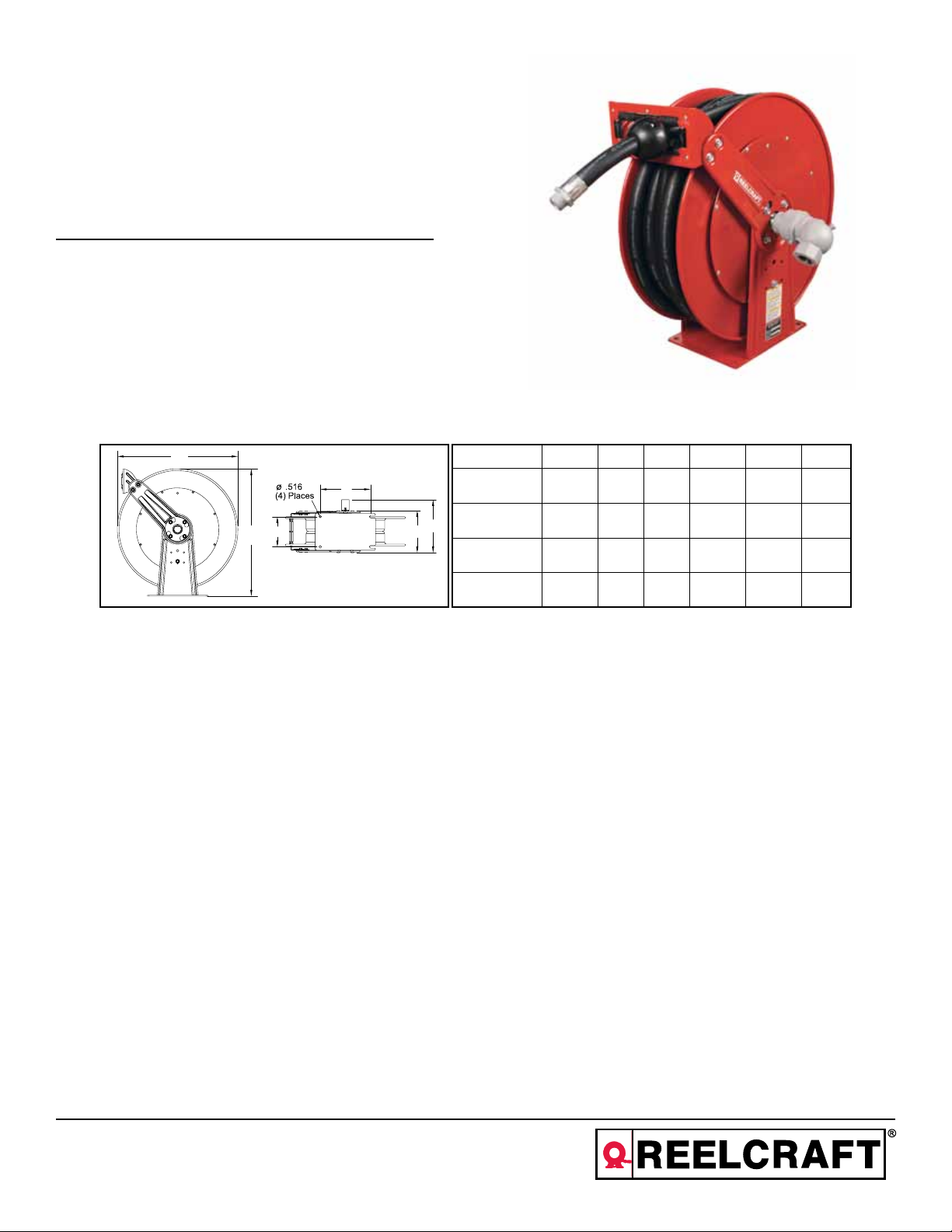
Dimensional Data
B
Part # A B C D E F
D
A
Personal Safety
Personal injury and/or equipment damage
may result if proper safety precautions are
not observed.
• Ensure that reel is properly installed
before connecting input and output
hoses.
• Bleed fluid/gas pressure from system
before servicing reel.
• Before connecting reel to supply line,
ensure that pressure does not exceed
maximum working pressure rating of
reel.
C
• Remember, even low pressure is very
dangerous and can cause personal in-
jury or death.
• Be aware of machinery and personnel
in work area.
• If a leak occurs in the hose or reel, remove system pressure immediately.
• A high tension spring assembly is contained within the reel. Exercise extreme
caution.
LP82000 OLP 25.375” 24” 10 6” 15.375” 9.375”
LP83000 OLP 25.375” 24” 10 6” 15.375” 9.375”
E
F
LPD83000 OLP 25.375” 24” 10.5” 7.875” 17.75” 9.375”
LPD84000 OLP 25.375” 24” 10.5” 7.875” 17.75” 9.375”
• Pull hose from reel by grasping the
hose itself, not the control valve.
• If reel ceases to unwind or rewind,
remove system pressure immediately.
Do not pull or jerk on hose!
• Treat and respect the hose reel as any
other piece of machinery, observing all
common safety practices.
Reelcraft Industries, Inc. • 2842 E Business Hwy 30, Columbia City, IN 46725
Ph: 800-444-3134 / 260-248-8188 • Fax: 800-444-4587 / 260-248-2605
Customer Service: 855-634-9109 • reelcraft@reelcraft.com • www.reelcraft.com
Form# 1161-1004 Rev: 5/2013
Page 2
Series LP80000 / LPD80000 Spring Driven Hose Reels
INSTALLATION INSTRUCTIONS
WARNING: Ensure that reel, hose, and
equipment are properly grounded. Use an
ohmmeter to check ground continuity.
Mounting
CAUTION: Unless reel was specified different-
ly when ordering, maximum installation height
is 16 feet. Do not exceed this distance.
Maximum Operating Temperature:
Low pressure (300 psi) = 150°F (66°C)
1. Unpack and inspect reel for damage.
Turn by hand to check for smooth operation. Check for completeness.
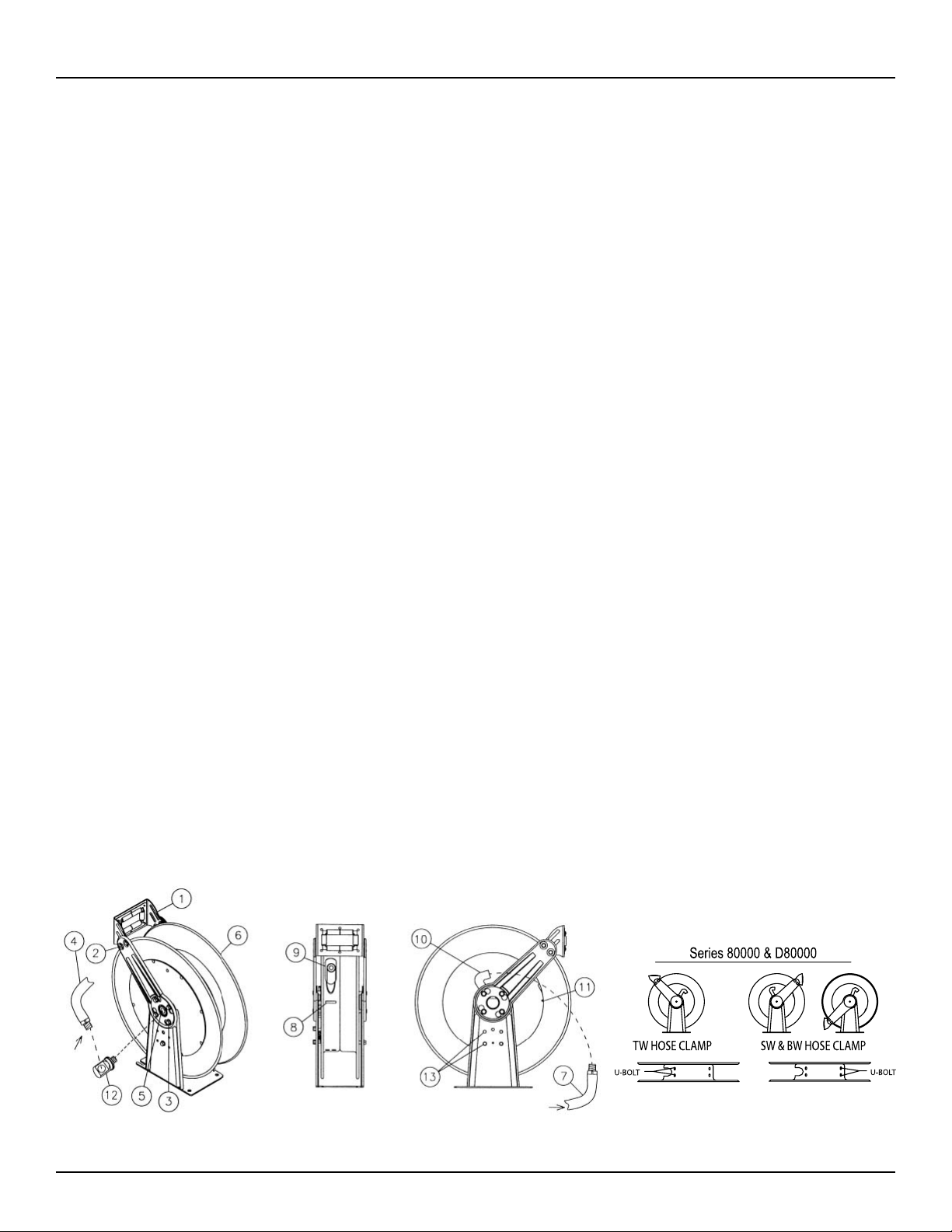
2. Configure reel for top, side or bottom
hose dispensing by removing the bolts
(2) from one side of the guide roller
bracket and loosening the four guide arm
bolts (3) on each side of the hose reel.
Rotate and remove each guide arm then
reinstall in the desired configuration. If
bottom wind is desired, bolts (13) and
bolts (2) must be removed and replaced
after the guide arm is in position.
CAUTION: When changing guide arm
positions, the U-bolt must be placed in the
proper location as instructed in figure A. The
reel can “latch out” during use if this instruction is not adhered to.
3. Position reel on floor, wall, or ceiling.
Secure into place using four (customer
supplied) bolts.
Installing the Input Hose
WARNING: Ensure that supply line pressure
does not exceed maximum working pressure
rating of reel. Apply pipe thread sealant to all
threads on standard reels. Do not overtighten
connection. Recommended torque not to
exceed 70 ft. lb.
CAUTION
input. Do not use rigid plumbing. The use of
rigid plumbing may void the warranty.
1. Apply thread sealant as directed and con-
2. For standard shaft and swivel reels, con-
: Use flexible hose connection at
nect swivel (12) to main shaft input (5).
nect customer supplied inlet hose (4) to
swivel input as indicated in illustration.
Installing the Output Hose
WARNING: Use extreme caution; reel under
tension. Avoid releasing latch mechanism.
CAUTION: Apply pipe thread sealant to all
threads on standard reels. Do not overtighten
connection. Recommended torque not to
exceed 70 ft. lb.
1. Manually turn sheave (6) until spring is
tight, back off 3 turns, then latch.
2. Route output hose (7) through roller
bracket (1), U-bolts (8), then through
cutout (9) in spool as indicated in illustration.
3. Connect output hose (7) to gooseneck
(10) as indicated in illustration.
4. Verify U-bolt position conforms with
guide arm position using label inside
spool. Tighten nuts (11) on U-bolt (8).
5. Charge hose. Momentarily open control
valve to purge hose of gases. When fluid
appears at control valve, close valve.
With hose fully charged, release latch and
wind output hose onto reel.
6. Install hose bumper assembly.
ADJUSTMENTS
WARNING: Use extreme caution; reel under
tension. Avoid releasing latch mechanism.
If necessary, adjust spring tension on reel by
manually adding or removing wraps of hose
from spool, one wrap at a time, until desired
tension is obtained. Manually add wraps to
increase tension. Remove wraps to decrease
tension.
CAUTION: When adding wraps of hose, add
just enough wraps to achieve the desired
tension without exceeding the winding mechanism’s spring capacity. Properly tensioned
reels allow all hose to be freely removed from
the spool until the point of U-bolt contact.
Damage to the winding mechanism will result
if spring is over-tensioned.
SERVICE INSTRUCTIONS
User servicing of the reel is limited to replacing input/output hoses only. Refer all other
repairs to an authorized service person or
directly to Reelcraft. Failure to do so may
result in personal injury and/or equipment
damage and may void the warranty.
WARNING: Rewind hose on reel, then bleed
pressure from system before performing the
following procedures.
CAUTION: Remove all spring tension before
disassembling the hose reel. Do not attempt to
open the riveted spring case assembly.
1. Replace hoses in accordance with procedures given in “Installation Instructions”
section of this manual.
2. All mating moving parts have been factory lubricated as required.
Page 2
Figure A
www.reelcraft.com
Page 3
Series LP80000 / LPD80000 Spring Driven Hose Reels
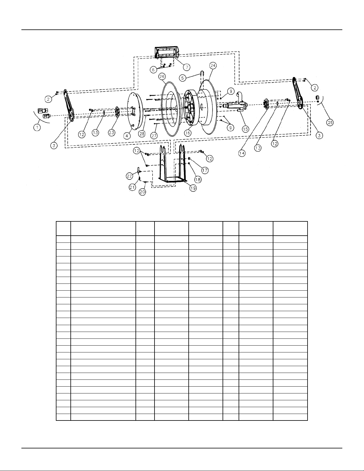
ITEM DESCRIPTION
1 Swivel assembly 1 S600979-1 S600979-1 1 S600979-1 S600979-1
2 5/16-18 x 1/2” hex flange screw 4 S2-51 S2-51 4 S44-10 S44-10
3 Guide arm 2 261299 261299 2 261299 261299
4 Spring & case assembly 1 S600645-2 6006945-1 1 S600645-3 S600645-3
5 U-bolt 1 3-117440 5-117440 1 5-117440 261395
6 5/16-18 locknut 8 300107 300107 4 300107 300107
7 Roller bracket assembly 1 S600642 S600642 1 S600642 S600705
9 1/4-20 locknut 2 300070 300070 8 300070 300070
12 3/8-16 x 5/8” screw 9 S44-2 S44-2 9 S44-2 S44-2
13 1 3/8” snap ring 2 S140-34 S140-34 2 S140-34 S140-34
14 Bearing & nut-sert assembly 1 S600651 S600651 1 S600651 S600651
15 Ratchet, flow casting 1 261306-2 261306-2 1 S261590-1 S261591-1
16 Spool spacer --- None None 1 261393 261393
17 1/2-20 x 5/8” hex nut 1 S280-8 S280-8 1 S280-8 S280-8
18 3/8-16 hex nut ** --- None None 1 S281-6 S281-6
18 10-32 Nyloc nut --- None None 1 S82-15 S82-15
19 Base & upright assembly 1 600641 600641 1 600704 600704
20 Latch spring stud ** --- None None 1 261351 261351
20 Shoulder screw --- None None 1 S393-2 S393-2
21 Latch spring 1 S260067 S260067 1 S260067 S260067
22 Latch pawl assembly 1 S600018 S600018 1 S600018 S600018
23 Bearing & flange assembly 1 S600644 S600644 1 S600644 S600644
24 Sheave, hose opening 1 600649 600649 1 261307 261307
25 Pipe plug 1 S183-53 S183-54 1 S183-54 261396
26 Sheave, springcase --- None None 1 261308 261308
27 Screw, 1/4-20 x 2 1/2” --- None None 8 S2-411 S2-411
28 Screw, 5/16-18 x 2 1/2” --- None None 3 S2-511 S2-511
QTY
LP82000 OLP LP83000 OLP
(LP)
QTY
LPD83000 OLP LPD84000 OLP
(LPD)
www.reelcraft.com
**Prior to March 2012
Page 3
Page 4

Instrucciones de Operacion
Series LP80000 / LPD80000
Carreteles para Mangueras
LP82000 OLP LP83000 OLP
LPD83000 OLP LPD84000 OLP
IMPORTANTE
Lea este manual detenidamente antes de
instalar, operar o dar servicio a este equipo.
Data Dimensional
B
Part # A B C D E F
D
A
Seguridad Personal
Podrían ocurrir lesiones personales y/o
daños en el equipo si no se siguen las instrucciones de seguridad adecuadas.
• Asegúrese de que el carretel esté instalado apropiadamente antes de conectar
las mangueras de entrada y de salida.
• Purgue la presión de fluidos/gases del
sistema antes de suministrar servicio al
carretel.
• Antes de conectar el carretel a la línea
de suministro, asegúrese de que la presión no exceda la clasificación máxima
de la presión operativa del carretel.
C
• Recuerde que aún la presión baja es
muy peligrosa y podría causar lesiones
personales o la muerte.
• Esté atento y fíjese si hay maquinaria o
personas en el área de trabajo.
• Si existe una fuga en la manguera o en
el carretel, elimine inmediatamente la
presión del sistema.
• Hay un ensamblaje de resorte de tensión alta en el interior del carretel. Sea
extremadamente precavido.
• Jale la manguera del carretel sujetando
la manguera, y no la válvula de control.
LP82000 OLP 25.375” 24” 10 6” 15.375” 9.375”
LP83000 OLP 25.375” 24” 10 6” 15.375” 9.375”
E
F
LPD83000 OLP 25.375” 24” 10.5” 7.875” 17.75” 9.375”
LPD84000 OLP 25.375” 24” 10.5” 7.875” 17.75” 9.375”
• Si el carretel deja de desenrollarse o
enrollarse, elimine inmediatamente la
presión del sistema. ¡No jale ni sacuda
la manguera!
• Trate y utilice el carretel de manguera
como lo haría con cualquier otra máquina, siguiendo todas las pautas de
seguridad generales.
Page 4
Reelcraft Industries, Inc. • 2842 E Business Hwy 30, Columbia City, IN 46725
Ph: 800-444-3134 / 260-248-8188 • Fax: 800-444-4587 / 260-248-2605
Customer Service: 855-634-9109 • reelcraft@reelcraft.com • www.reelcraft.com
Form# 1161-1004 Rev: 5/2013
Page 5

Series LP80000 / LPD80000 Carreteles para Mangueras
INSTRUCCIONES DE INSTALACIÓN
ADVERTENCIA: Asegúrese de que el carretel,
la manguera y el equipo estén conectados a
tierra apropiadamente. Use un ohmiómetro para
revisar la continuidad de la conexión a tierra.
Montaje
PRECAUCIÓN: A menos de que el carretel
haya sido suministrado con características
diferentes al ordenarlo, la altura máxima de
instalación es de 16 pies. No exceda esta altura.
Temperatura Máxima de Operación:
Presión Baja (300 p.s.i.) = 150°F, (21,10 kg/cm2 /
300 p.s.i.) = 65,5° C (150° F)
1. Desempaque e inspeccione el carretel para ver si
se ha dañado. Hágalo girar a mano para cerciorarse de que gira suavemente. Asegúrese de que
todas las piezas estén incluidas.
2. Configure el carretel para poder jalar la manguera
desde arriba, abajo o lateralmente quitando los
pernos (2) a un lado de la abrazadera guía de rodillo y aflojando los cuatro pernos de brazo guía
(3) a cada lado del carretel de manguera. Gire y
quite cada brazo guía e instálelo nuevamente en
la
configuración deseada. Si desea poder jalar la
manguera desde abajo, tiene que remover y reemplacer los pernos (13) y (2) después de brazo
guía está a la posición deseada.
ATENCIÓN: Al cambiar las posiciones del brazo
guía, el perno en U debe colocarse en la posición
correcta, como se indica en la figura A. Si no se
cumple con esta instrucción, el carrete puede
bloquearse durante el uso.
3. Coloque el carretel en el piso, pared o cielo raso.
Fíjelo en su lugar usando cuatro
pernos (proporcionados por el cliente).
Instalación de la manguera de entrada
ADVERTENCIA: Asegúrese de que la presión
de la línea de suministro no exceda la
clasificación máxima de presión operativa
indicada en el carretel. Aplique sellador para
roscas de tubería en todas las roscas de los
carreteles estándar. No apriete excesivamente la
conexión. La torsión recomendada no debe exceder
70 pies libra.
PRECAUCIÓN: Use una conexión de
manguera flexible en el punto de entrada. No
use tubería rígida. El uso de fontaneria rigida
puede anular la garantia.
1. Aplique el sellador para roscas tal como se
indica y conecte el eslabón giratorio (12) a la
entrada del eje principal (5).
2. Para los carreteles de eje y eslabón giratorio
estándar, conecte una manguera de entrada proporcionada por el cliente (4) al punto de entrada
del eslabón giratorio, tal como se indica en la
ilustración.
Instalación de la manguera de salida
ADVERTENCIA: Sea extremadamente
precavido; el carretel se encuentra bajo
tensión. Evite desenganchar el mecanismo de
aldaba.
PRECAUCIÓN: Aplique sellador para roscas de tubería en todas las roscas de los carreteles estándar.
No apriete excesivamente la conexión. La torsión
recomendada no debe exceder 70 pies libra.
1. Gire manualmente la polea acanalada (6) hasta
que el resorte esté apretado, gírela hacia atrás
tres veces, y después fíjela.
2. Oriente la manguera de salida (7) a través de la
abrazadera de rodillo (1) y los pernos en U (8),
y después a través del orificio en el molinete, tal
como se indica en la ilustración.
3. Conecte la manguera de salida (7) al cuello de
cisne (10), tal como se indica en la
ilustración.
4. Verifique que la posición de los pernos en U
armonizan con el posicionamiento del brazo guía,
usando la etiqueta en el interior del molinete.
5. Cargue la manguera. Abra momentáneamente la
válvula de control para purgar los gases en la
manguera. Cierre la válvula cuando el fluido aparezca en la válvula de control. Con la manguera
completamente cargada, suelte la aldaba y enrolle
la manguera de salida alrededor del carretel.
6. Instale el ensamblaje de paragolpes.
AJUSTES
ADVERTENCIA: Sea extremadamente
precavido: el carretel se encuentra bajo
tensión. Evite desenganchar el mecanismo de
aldaba. Si es necesario, ajuste la tensión del
resorte en el carretel agregando o quitando
manualmente envolturas de manguera del
molinete una a la vez, hasta obtener la tensión
deseada. Agregue manualmente dichas
envolturas para aumentar la tensión, y quítelas
para disminuirla.
PRECAUCIÓN: Al agregar envolturas de
manguera, agregue únicamente el número
suficiente para obtener la tensión deseada sin
exceder la capacidad del resorte del
mecanismo de devanado. Los carreteles con
una tensión adecuada permiten sacar toda la
manguera del molinete hasta llegar al punto de
contacto con el perno en U. La tensión
excesiva del resorte dañará el mecanismo de
devanado.
INSTURCCIONES DE SERVICIO
El suministro de servicio por parte del usuario
se limita únicamente a reemplazar mangueras
de entrada/salida. Remita cualquier otra
reparación a un técnico de servicio autorizado
o directamente a Reelcraft. El no hacerlo podría
resultar en lesiones personales y/o daños del
equipo que podrían anular la garantía.
ADVERTENCIA: Enrolle la manguera en el
carretel, y después purgue la presión del
sistema antes de efectuar los siguientes
procedimientos.
PRECAUCIÓN: Elimine toda la tensión del
resorte antes de desensamblar el carretel de
manguera. No trate de abrir el ensamblaje
remachado de la caja de resorte.
1. Reemplace la manguera de acuerdo con los
procedimientos de la sección “Instrucciones de
Instalación” de este manual.
2. Todas las partes móviles correspondientes han
sido lubricadas adecuadamente en la
www.reelcraft.com
Figure A
Page 5
Page 6

Series LP80000 / LPD80000 Carreteles para Mangueras
ART.
NO.
1 Ensamblaje del eje giratoria 1 S600979-1 S600979-1 1 S600979-1 S600979-1
2 5/16-18 x 1/2” tornillo 4 S2-51 S2-51 4 S44-10 S44-10
3 Brazo Guía 2 261299 261299 2 261299 261299
4 Ensamblaje de Resorte y Caja 1 S600645-2 6006945-1 1 S600645-3 S600645-3
5 Perno en U 1 3-117440 5-117440 1 5-117440 261395
6 Tuerca de Sujeción 5/16-18 8 300107 300107 4 300107 300107
7 Ensamblaje de Abrazadera de Rodillo 1 S600642 S600642 1 S600642 S600705
9 1/4-20 Tuerca de Sujeción 2 300070 300070 8 300070 300070
12 3/8-16 x 5/8” tornillo 9 S44-2 S44-2 9 S44-2 S44-2
13 1 3/8” Aro de Resorte 2 S140-34 S140-34 2 S140-34 S140-34
14 Brida con Cojinete y Ensamblaje Nut-Sert 1 S600651 S600651 1 S600651 S600651
15 Trinquete, Bastidor Del Flujo 1 261306-2 261306-2 1 S261590-1 S261591-1
16 Espaciador Del Carrete --- -------- -------- 1 261393 261393
17 Tuerca de hexagonal 1/2-20 x 5/8” 1 S280-8 S280-8 1 S280-8 S280-8
18 3/8-16 Tuerca de hexagonal ** --- -------- -------- 1 S281-6 S281-6
18 10-32 Tuerca de Nyloc --- -------- -------- 1 S82-15 S82-15
19 Ensamblaje de Bajo Y Vertical 1 600641 600641 1 600704 600704
20 Perno prisionero del resorte de cierre ** --- -------- -------- 1 261351 261351
20 Tornillo de hombro --- -------- -------- 1 S393-2 S393-2
21 Resorte de cierre 1 S260067 S260067 1 S260067 S260067
22 Ensamblaje del gatillo del cierre 1 S600018 S600018 1 S600018 S600018
23 Ensamblaje del cojinete y del reborde 1 S600644 S600644 1 S600644 S600644
24 Polea acanalada, abertura de la Manguera 1 600649 600649 1 261307 261307
25 Tapón de tuberia 1 S183-53 S183-54 1 S183-54 261396
26 Polea acanalada, springcase --- -------- -------- 1 261308 261308
27 Tornillo, 1/4-20 x 2 1/2” --- -------- -------- 8 S2-411 S2-411
28 Tornillo, 5/16-18 x 2 1/2” --- -------- -------- 3 S2-511 S2-511
Descripción
NO.
REQ.
LP82000 OLP LP83000 OLP
(LP)
NO.
REQ.
LPD83000 OLP LPD84000 OLP
(LPD)
Page 6
** Antes del marzo de 2012
www.reelcraft.com
Page 7

Instructions D’Opération
Série LP80000 / LPD80000
Enrouleurs de Tuyau
LP82000 OLP LP83000 OLP
LPD83000 OLP LPD84000 OLP
IMPORTANT
Lisez ce manuel soigneusement avant
d’installer, actionner, ou entretenir cet
èquipment.
Dimensions
B
Part # A B C D E F
D
A
Sécurité
Podrían ocurrir lesiones personales y/o
daños en el equipo si no se siguen las instrucciones de seguridad adecuadas.
• Assurez-vous que l’enrouleur est correctement installé avant de raccorder
les tuyaux d’entrée et de sortie.
• Evacuez tout liquide/gaz sous pression du système avant d’entreprendre
l’entretien de l’enrouleur.
• Avant de raccorder l’enrouleur à la
ligne d’alimentation, assurez-vous que
la pression n’excède pas la pression de
fonctionnement nominale maximum de
l’enrouleur.
C
• Souvenez-vous, même les pressions
basses sont dangereuses et peuvent
provoquer des blessures ou la mort.
• Ayez conscience des machines et des
personnes se trouvant dans la zone de
travail.
• Si une fuite apparaît dans le tuyau ou
l’enrouleur, décompressez le système
immédiatement.
• L’enrouleur comporte un assemblage
à ressort de haute tension. Observez la
plus grande prudence.
LP82000 OLP 25.375” 24” 10 6” 15.375” 9.375”
LP83000 OLP 25.375” 24” 10 6” 15.375” 9.375”
E
F
LPD83000 OLP 25.375” 24” 10.5” 7.875” 17.75” 9.375”
LPD84000 OLP 25.375” 24” 10.5” 7.875” 17.75” 9.375”
• Sortez le tuyau de l’enrouleur en tirant sur le tuyau lui-même, pas sur
l’embout.
• Si l’enrouleur arrête d’enrouler ou de
dérouler, décompressez le système immédiatement. Ne pas tirer ou secouer le
tuyau !
• Comme avec toute autre machine,
traitez l’enrouleur de tuyau avec respect, en observant les consignes de
sécurité habituelles.
Page 7
Reelcraft Industries, Inc. • 2842 E Business Hwy 30, Columbia City, IN 46725
Ph: 800-444-3134 / 260-248-8188 • Fax: 800-444-4587 / 260-248-2605
Customer Service: 855-634-9109 • reelcraft@reelcraft.com • www.reelcraft.com
Form# 1161-1004 Rev: 5/2013
Page 8

Série LP80000 / LPD80000 Enrouleurs de Tuyau
CONSIGNES D’INSTALLATION
AVERTISSEMENT : Assurez-vous que l’enrouleur,
le tuyau et l’équipement sont correctement mis à la
terre. Utilisez un ohmmètre pour vous assurer de la
continuité du circuit de mise à la terre.
Montage
ATTENTION : A moins de spécifications différentes
lors de la commande, la hauteur d’installation maximum de l’enrouleur est de 4,90 m (16 pieds). Ne
dépassez pas cette hauteur.
Température de fonctionnement maximum :
Basse pression (21,10 kg/cm2 / 300 p.s.i.) =
65,5° C (150° F)
Pression moyenne (140,65 kg/cm2 / 2000 p.s.i.)
= 98,9° C (210° F)
1. Déballez l’enrouleur et assurez-vous qu’il n’est
pas endommagé. Faites-le tourner à la main
pour vous assurer de son bon fonctionnement.
Assurez-vous qu’il est complet.
2. Configurez l’enrouleur pour une distribution
supérieure, latérale ou inférieure du tuyau en
retirant les vis (2) d’un côté du support du guide
à molette et en desserrant les quatre vis du bras
de guidage (3) de chaque côté de l’enrouleur de
tuyau. Pivotez et enlevez chaque bras de guidage, puis remettez-les en place dans la position
voulue. Pour une distribution inférieure, enlevez
et remplacez les vis (13) et (2) après le bras de
guidage est à la position désirée.
ATTENTION: Lorsque vous changez la position
du bras de guidage, le boulon en U doit se trouver dans l’emplacement indiqué sur la figure A.
L’enrouleur peut se débloquer en cours d’utilisation
si cesinstructions ne sont pas respectées.
3. Placez l’enrouleur sur le sol, le mur ou le plafond. Fixez en place à l’aide de quatre vis (non
fournies).
Installation du tuyau d’entrée
AVERTISSEMENT : Assurez-vous que la
pression de la ligne d’alimentation n’excède pas la
pression de fonctionnement nominale maximum de
l’enrouleur. Appliquez un produit d’étanchéité sur le
filetage de tous les tuyaux des enrouleurs standard.
Ne serrez pas excessivement les raccords. Le moment de torsion recommandé ne doit pas dépasser
98 Nm (70 ft.lb).
ATTENTION : Utilisez des raccords de tuyau flexibles à l’entrée. N’utilisez pas de tuyauterie rigide.
1. Appliquez le produit d’étanchéité comme indiqué
et raccordez le pivot (12) à l’entrée de l’axe principal (5).
2. Pour les enrouleurs à pivot et axe standard, raccordez le tuyau d’entrée (4) (non fourni) à l’entrée
du pivot comme indiqué dans
l’illustration.
Installation du tuyau de sortie
AVERTISSEMENT : Observez une extrême pru-
dence ; l’enrouleur est sous la tension d’un ressort.
Evitez de relâcher le mécanisme de verrouillage.
ATTENTION : Appliquez du produit d’étanchéité sur
tous les filetages des enrouleurs standard.Ne pas
serrer excessivement les raccords. Le moment de
torsion recommandé ne doit pas dépasser 98 Nm (70
ft.lb). Ne pas serrer excessivement les raccords.
Le moment de torsion recommandé ne doit pas dépasser 98 Nm (70 ft.lb).
1. Tournez manuellement la poulie (6) jusqu’à ce
que le ressort soit tendu, relâchez de trois tours,
puis verrouillez.
2. Faites passer le tuyau (7) par le support à molette
(1), l’étrier de serrage (8), puis par la découpe du
tambour (9), comme indiqué dans l’illustration.
3. Raccordez le tuyau de sortie (7) au col de cygne
(10), comme indiqué dans l’illustration.
4. Assurez-vous que la position de l’étrier de serrage est conforme à celle du bras de guidage en
utilisant les inscriptions situées à l’intérieur du
tambour.
5. Remplissez le tuyau. Ouvrez provisoirement la
valve afin de purger les gaz du tuyau. Fermez la
valve lorsque le liquide y apparaît. Une fois le
tuyau entièrement rempli, déverrouillez le loquet
et enroulez le tuyau de sortie sur l’enrouleur.
6. Installez l’assemblage du butoir.
AJUSTEMENTS
AVERTISSEMENT : Observez une extrême
prudence ; l’enrouleur est sous la tension d’un ressort. Evitez de relâcher le mécanisme de
verrouillage. Si cela est nécessaire, ajustez la tension du ressort de l’enrouleur en ajoutant ou en enlevant manuellement des tours detuyau du tambour,
un tour à la fois, jusqu’à ce que la tension désirée
soit obtenue. Ajoutez manuellement des tours pour
augmenter la tension. Enlevez manuellement des
tours pour abaisser la tension.
ATTENTION : Lors de l’ajout de tours de tuyau,
ajoutez juste assez de tours afin d’obtenir la
tension désirée sans dépasser la capacité du ressort
du mécanisme d’enroulement. Un enrouleur dont la
tension est correctement ajustée permet de dérouler
librement tout le tuyau jusqu’au point de contact
avec l’étrier de serrage. Un ressort surtendu endommagera le mécanisme d’enroulement.
CONSIGNES D’ENTRETIEN
L’entretien de l’enrouleur par l’utilisateur se limite
uniquement au remplacement des tuyaux d’entrée et
de sortie. Toute autre réparation doit être confiée à
un technicien autorisé ou directement à Reelcraft. Le
manquement à cette consigne peut conduire à des
blessures corporelles et/ou à des dommages matériels, ainsi qu’à l’annulation de la garantie.
AVERTISSEMENT : Enroulez le tuyau sur le
tambour, puis dépressurisez le système avant de
procéder aux opérations suivantes.
ATTENTION : Détendez entièrement le ressort
avant de désassembler l’enrouleur. Ne pas essayer
d’ouvrir l’assemblage riveté du boîtier de res
1. Remplacez les tuyaux en observant les instructions contenues dans la section “Consignes
d’installation” de cette notice.
2. Toutes les pièces mobiles emboîtées ont été lubrifiées à l’usine, comme requis.
sort.
Page 8
Figure A
www.reelcraft.com
Page 9

Série LP80000 / LPD80000 Enrouleurs de Tuyau
ART
N°.
1 Assemblage du pivot 1 S600979-1 S600979-1 1 S600979-1 S600979-1
2 Vis de 5/16-18 x 1/2 pouce 4 S2-51 S2-51 4 S44-10 S44-10
3 Bras de guidage 2 261299 261299 2 261299 261299
4 Ass. du ress. et du boît 1 S600645-2 6006945-1 1 S600645-3 S600645-3
5 Etrier de serrage 1 3-117440 5-117440 1 5-117440 261395
6 Contre-écrou de 5/16-18 pouce 8 300107 300107 4 300107 300107
7 Assemblage du support à molette 1 S600642 S600642 1 S600642 S600705
9 Contre-écrou de 1/4-20 pouce 2 300070 300070 8 300070 300070
12 3/8-16 x 5/8” vis 9 S44-2 S44-2 9 S44-2 S44-2
13 1 anneau ressort de 3/8” 2 S140-34 S140-34 2 S140-34 S140-34
Assemblage de l’embase avec roulement
14
et Nut-Sert
15 Rachet, Bâti D’Écoulement 1 261306-2 261306-2 1 S261590-1 S261591-1
16 Entretoise De Bobine --- None None 1 261393 261393
17 Ecrou hexagonal de 1/2-20 x 5/8 pouce 1 S280-8 S280-8 1 S280-8 S280-8
18 3/8-16 Écrou De Sortilège ** --- None None 1 S281-6 S281-6
18 10-32 Écrou de Nyloc --- None None 1 S82-15 S82-15
19 Ass. de la base et du montantl 1 600641 600641 1 600704 600704
20 Goujon de ressort de verrou ** --- None None 1 261351 261351
20 Vis d’épaule --- None None 1 S393-2 S393-2
21 Ressort de verrou 1 S260067 S260067 1 S260067 S260067
22 Assemblage de cliquet 1 S600018 S600018 1 S600018 S600018
23 Assemblage du roulement et de l’embase 1 S600644 S600644 1 S600644 S600644
24 Poulie, ouverture de tuyau 1 600649 600649 1 261307 261307
25 Bouchond’ étanchéité 1 S183-53 S183-54 1 S183-54 261396
26 Poulie, Springcase --- None None 1 261308 261308
27 Vis, 1/4-20 x 2 1/2” --- None None 8 S2-411 S2-411
28 Vis, 5/16-18 x 2 1/2” --- None None 3 S2-511 S2-511
DÉSCRIPTION
N° REQ.
LP82000 OLP LP83000 OLP
(LP)
1 S600651 S600651 1 S600651 S600651
N° REQ.
(LPD)
LPD83000 OLP LPD84000 OLP
www.reelcraft.com
** Avant le mars 2012
Page 9
 Loading...