

Page 1
Operating Instructions
Series L NM400 Cord Reels
Model Numbers:
L NM450 163 X L NM450 123 X
L NM450 143 X L NM440 124 X
L NM445 144 X L NM440 103 X
L NM425 123 X L NM430 104 X
IMPORTANT SAFETY INSTRUCTIONS
Please read this manual carefully and follow its instructions. Improper use or failure to follow these instructions could result in serious
injury, death or property damage. Operators should be instructed in the safe and proper use and maintenance of this product. Keep this
manual for future reference.
The following safety precautions call attention to potentially dangerous conditions.
DANGER: Immediate hazards which WILL result in severe personal injury or death.
WARNING: Hazards or unsafe practices which COULD result in severe personal injury or death.
CAUTION: Hazards or unsafe practices which MAY result in minor personal injury or product or property damage.
INSTALLATION
Lock out all electrical power and remove all spring tension from the reel before opening any
WARNING:
WARNING:
CAUTION:
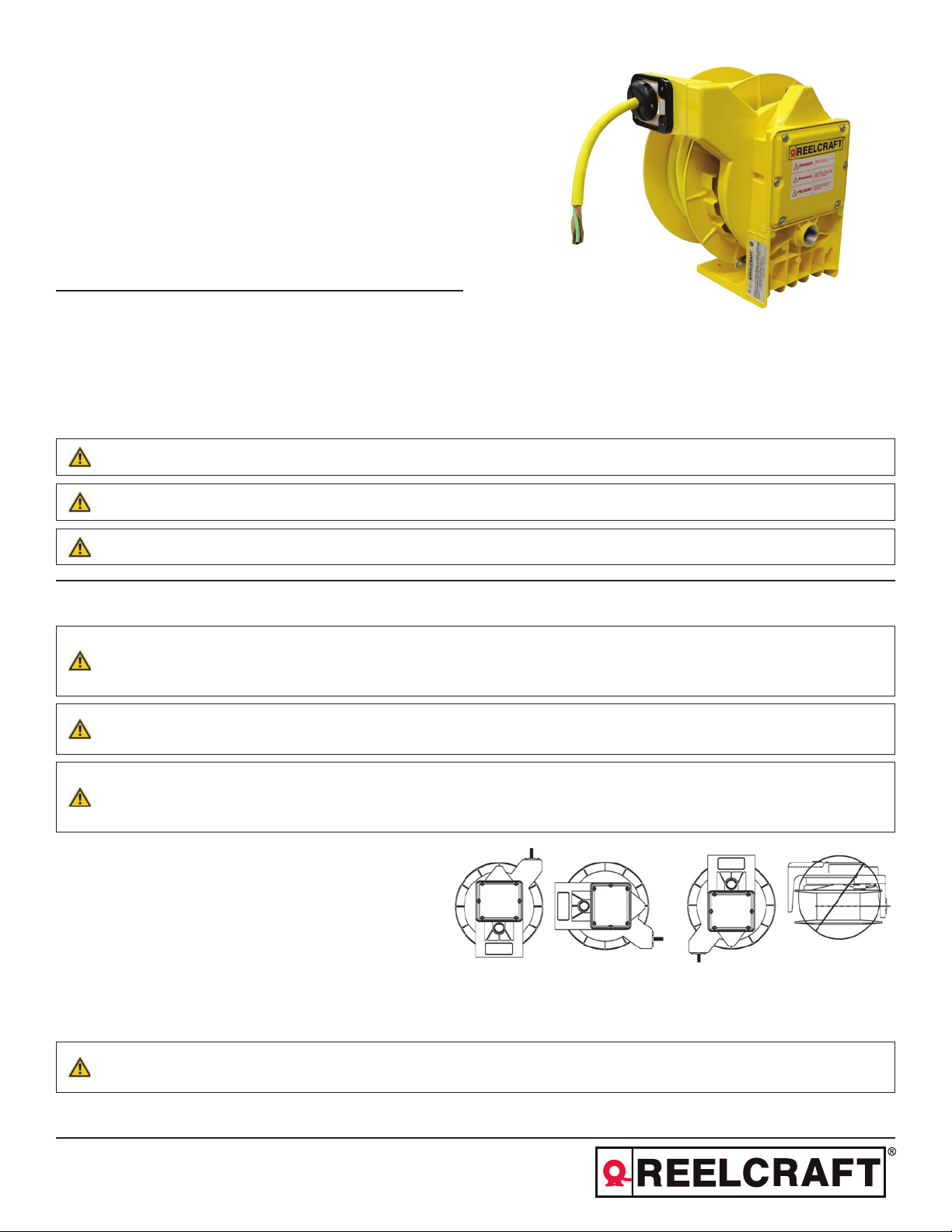
MOUNTING
The fixed base of the reel allows mounting in several different
positions including base up, base down, or wall mounted.
Here are general mounting requirements:
• Main-shaft must be horizontal.
• Centerline of the spool assembly must be in line with the cable run.
• When mounted overhead in base up position, add a secondary chain, bracket or other safety device to prevent reel from falling in case
the mounting bolts are removed or become loosened by vibration.
enclosure or performing any service to this reel. Make sure all circuits carry appropriate fuse
protection. Hazards or unsafe practices COULD result in severe personal injury or death.
Failure to read, understand, and follow these instructions creates hazards that COULD result in
personal injury or death.
Instruct operators in the safe, proper use, and maintenance of the reel. Keep this manual for future
reference. Hazards or unsafe practices MAY result in minor personal injury or product or property
damage.
DANGER:
Reelcraft Industries, Inc. • 2842 E Business Hwy 30, Columbia City, IN 46725
Ph: 800-444-3134 / 260-248-8188 • Fax: 800-444-4587 / 260-248-2605
Customer Service: 855-634-9109 • reelcraft@reelcraft.com • www.reelcraft.com
A secondary safety cable or chain is to be attached to all reels mounted overhead to prevent reel from
falling. Immediate hazards WILL result in severe personal injury or death.
Form# 1304-318 Rev: 3/2018
Page 2
Series L NM400 Cord Reels
All reels mounted over head should have a secondary support chain to protect personnel in case of structure or mounting component
failure. Attach one end of secondary support chain or cable to secondary support point on reel. Attach other end of secondary support
chain or cable to a support component other than that which supports the reel. The chain or cable should be as short as possible allowing
reel to drop no more than 6 to 12 inches if the primary connection is released. A secondary support is offered as an accessory item.
PIVOT BASE
If optional pivot base is used, four roller cable guide reel will align reel to direction of cable pull.
WIRING
NOTE: The green wire has been grounded to the frame of
the reel and spool, and cannot be used as a power
conductor.
A convenient one inch pipe thread opening has been provided at the
bottom of the enclosure in base for connecting standard water tight
cable connectors or conduit fitting--fittings not supplied. Individual
power connections are made to the collector ring bus wires inside
the junction box enclosure in base using commercially available
twist on wire connectors or compression splices.
Wire Color Number Wire Color Number
L1 black 1 L1 black 1
N white 2 L2 white 2
L3 red 3 L3 red 3
G green 4 G green 4
amp 220 v
1 Phase 3 Phase
WIRING SUPPLY CONNECTION
NOTE: See “Service, Working Cable Replacement/Installation” if cable needs to be installed.
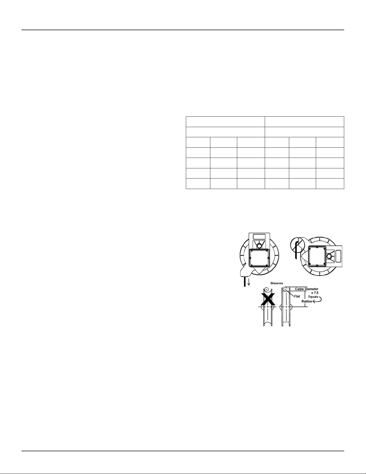
ROLLER GUIDE AND SHEAVES
Cable must exit guide in-line with pulling direction. If not, rotate guide arm as needed.
The cable guide position is set by rotating spring pocket assembly. Loosen the three
clamps holding spring pocket assembly in place by unscrewing the three hex head
bolts. Unless required, do not completely remove bolts or clamps. Reposition guide
as required, making sure clamps straddle ribs on outside diameter of spring pocket
assembly and retighten hex head bolts.
Sheaves are used to bend cable around corners. Typical minimum bend radius of
the sheave should be about 7.5 x cable diameter. Requirements can vary depending
on cable manufacturer specifications. Sheaves should have flat surfaces for cable to
ride on. The movement of cable through a sheave should be in the same plane as the
cable spool. Changing planes can greatly reduce cable life.
CABLE WINDING
There are many types of cable that may be installed on your cable reel depending on application. Select the cable most appropriate for
your application requirements. Many cables come from the factory with a wax-like film that can encourage uneven wrapping. At initial set
up it is common to use a dry lubricant (talc powder), or silicone based grease to encourage more even winding. Also critical to proper
winding is the adequate setting of “Spring Tension”. See appropriate section. In some cases sheaves and unanticipated application
features can require more tension than offered with standard reels. Contact factory for application assistance.
Page 2
www.reelcraft.com
Page 3

Series L NM400 Cord Reels
OPERATION
RATCHET LOCK
All models are supplied with a ratchet lock that works in any position. If ratchet lock is not
required--constant tension--, move spring clip and spring to adjacent cable guide screw.
SPRING TENSION
CAUTION:
CAUTION:
NOTE: A minimum of 2 pre-tension turns is required. Additional turns can be added as long as one unused spring turn
remains when cable is fully extended. If entire cable cannot be pulled out, decrease spring tension until a full one turn
remains.
All reels require pre-tensioning turns to spool assembly before
connecting free end of working cable. Set spring tension by turning
fully wrapped reel through a specific number of revolutions or turns.
Number of pre-tension turns depends on application and desired
tension. A minimum of 2 set up turns is needed for most
applications. Additional tension may be added by repeating
above process. After tension is set, connect cable free end. Failure
to pre-tension reel may result in insufficient tension to retract and
may shorten spring life.
Do not connect working end of cable until the reel is properly pretensioned. Hazards or unsafe
practices MAY result in minor personal injury or product or property damage.
Failure to test for adequate spring revolutions can cause spring damage. Hazards or unsafe practices
MAY result in minor personal injury or product or property damage.
SERVICE
MAIN SPRING
Always disconnect electrical power before dismantling any part of the reel. Fuse size must not be
WARNING:
WARNING:
WARNING:
If reel will not develop tension or retract cable, spring assembly may need to be replaced. Remove junction box cover. Disconnect lineinput wires from collector ring bus wires. Also disconnect cable free end and allow spring to unwind completely. Remove screw, shaft
retainer, then pull complete spool assembly with cable from base. Remove cable guide, spring clip, ratchet spring, shoulder bolt and
ratchet pawl from spring pocket assembly. Remove spring pocket assembly from base and replace with new part. To reassemble, reverse
the above procedure making sure the dimple in the shaft retainer is toward the main shaft. Re-tension cable reel as per instructions.
www.reelcraft.com
greater than maximum amperage capacity of cable. Remove all spring tension before attempting any
service. Hazards or unsafe practices COULD result in severe personal injury or death.
To prevent personal injury, death or property damage, handle all springs with care. Use suitable
protective gloves for spring handling. Hazards or unsafe practices COULD result in severe personal
injury or death.
To prevent personal injury, death or property damage, hold center of spring down as the hub is pulled
out. If the center is allowed to rise up, the spring may escape from its container. Hazards or unsafe
practices COULD result in severe personal injury or death.
Page 3
Page 4

Series L NM400 Cord Reels
COLLECTOR RING REPLACEMENT
WARNING:
CAUTION:
Disconnect and lock out all power to reel and remove all tension on spring before servicing collector
ring assembly. Hazards or unsafe practices COULD result in severe personal injury or death.
Check continuity and replace all covers before turning on electrical power. Hazards or unsafe
practices MAY result in minor personal injury or product or property damage.
Check placement of brush holder assemblies to make sure terminal locations are centered between
WARNING:
the protruding lobes on the inner and outer drums. Hazards or unsafe practices COULD result in
severe personal injury or death.
NOTE: Check position of cable entry in relationship to studs marked by
“X” in figure. Replace subsequent brush assemblies in clockwise rotation.
To service the collector ring assembly, remove junction box cover and disconnect bus
wires in junction box. Remove cover, if required, and outer drum-half. Unclip brush
assembly from brush studs and remove. Notice position of brush assembly. Remove
all brush assemblies from collector ring. Loosen collector ring set screw and slide
collector ring off main shaft. To reassemble, reverse above procedure. The last brush
assembly--one closest to steel hub on collector ring--must be assembled on brush
studs indicated by the “X” in the figure to the right.
WORKING CABLE REPLACEMENT/INSTALLATION
WARNING:
Disconnect and lock out all power to reel and remove all tension on spring before servicing collector
ring assembly. Hazards or unsafe practices COULD result in severe personal injury or death.
CAUTION:
Check continuity and replace all covers before turning on electrical power. Hazards or unsafe
practices MAY result in minor personal injury or product or property damage.
NOTE: Cable seal is a bellows type seal designed to fit different size cables. Pull out the bellows in one direction and
cut the seal so that the through opening is at least 1/8” diameter smaller than the working cable. Always cut the seal
smaller than required. More of the seal may be cut off if necessary.
This procedure applies to both new installations and for replacement of working cable. To install/replace cable loosen seal cover and
cable seal. Remove cover, if required, and outer drum half. Loosen or remove cable clamp and individual conductors of working cable
from brush assemblies. Pull working cable through opening of inner drum and remove seal cover, and cable seal from old working cable.
Place seal cover and cable seal over replacement cable. To reassemble, reverse the above procedure. Be sure to connect working cable
conductors to the proper brush assembly. Re-tension spring.
Page 4
www.reelcraft.com
Page 5

Series L NM400 Cord Reels
www.reelcraft.com
Page 5
Page 6

Series L NM400 Cord Reels
Item
#
1 Clamp 3 Kit A Kit A Kit A Kit A
2 Bolt hex head M6 3 Kit A Kit A Kit A Kit A
3 Main shaft 1 263095 263095 263095 263095
4 Junction box gasket 1 263096 263096 263096 263096
5 Spring case assembly 1 263097 263097 263097 263098
6 Extension spring 1 263100 263100 263100 263100
7 Cable guide frame 1 Kit C Kit C Kit C Kit C
8 Roller shaft 4 Kit C Kit C Kit C Kit C
9 Roller 4 Kit C Kit C Kit C Kit C
10 Screw pan head M6x16mm 4 Kit C Kit C Kit C Kit C
11 Screw pan head M6x20mm 2 Kit C Kit C Kit C Kit C
12 Spring clip 1 263101 263101 263101 263101
13 Screw shoulder M8x10x16 1 263102 263102 263102 263102
14 Ratchet pawl 1 263103 263103 263103 263103
15 Cable clamp 1 263104 263104 263104 263104
16 Drum gasket 1 263105 263105 263105 263105
Copper brush assembly -
17
quantity one per # of conductors
18 Collector ring subassembly 1 263107 263108 263107 263107
19 Cable seal 1 263112 263112 263112 263112
20 Seal cover 1 263113 263113 263113 263113
Kit A Clamp kit - 3 sets, stainless steel 1 263110 263110 263110 263110
Kit B Pivot base - optional 1 263109 263109 263109 263109
Kit C Roller guide kit 1 263111 263111 263111 263111
Description
#
L NM450 143 X L NM445 144 X L NM425 123 X L NM450 163 X
Req.
3 or 4 263106 263106 263106 263106
Item
#
1 Clamp 3 Kit A Kit A Kit A Kit A
2 Bolt hex head M6 3 Kit A Kit A Kit A Kit A
3 Main shaft 1 263095 263095 263095 263095
4 Junction box gasket 1 263096 263096 263096 263096
5 Spring case assembly 1 263099 263099 263099 263099
6 Extension spring 1 263100 263100 263100 263100
7 Cable guide frame 1 Kit C Kit C Kit C Kit C
8 Roller shaft 4 Kit C Kit C Kit C Kit C
9 Roller 4 Kit C Kit C Kit C Kit C
10 Screw pan head M6x16mm 4 Kit C Kit C Kit C Kit C
11 Screw pan head M6x20mm 2 Kit C Kit C Kit C Kit C
12 Spring clip 1 263101 263101 263101 263101
13 Screw shoulder M8x10x16 1 263102 263102 263102 263102
14 Ratchet pawl 1 263103 263103 263103 263103
15 Cable clamp 1 263104 263104 263104 263104
16 Drum gasket 1 263105 263105 263105 263105
Copper brush assembly -
17
quantity one per # of conductors
18 Collector ring subassembly 1 263107 263108 263107 263108
19 Cable seal 1 263112 263112 263112 263112
20 Seal cover 1 263113 263113 263113 263113
Kit A Clamp kit - 3 sets, stainless steel 1 263110 263110 263110 263110
Kit B Pivot base - optional 1 263109 263109 263109 263109
Kit C Roller guide kit 1 263111 263111 263111 263111
Description
#
L NM450 123 X L NM440 124 X L NM440 103 X L NM430 104 X
Req.
3 or 4 263106 263106 263106 263106
Page 6
www.reelcraft.com
 Loading...