

Page 1
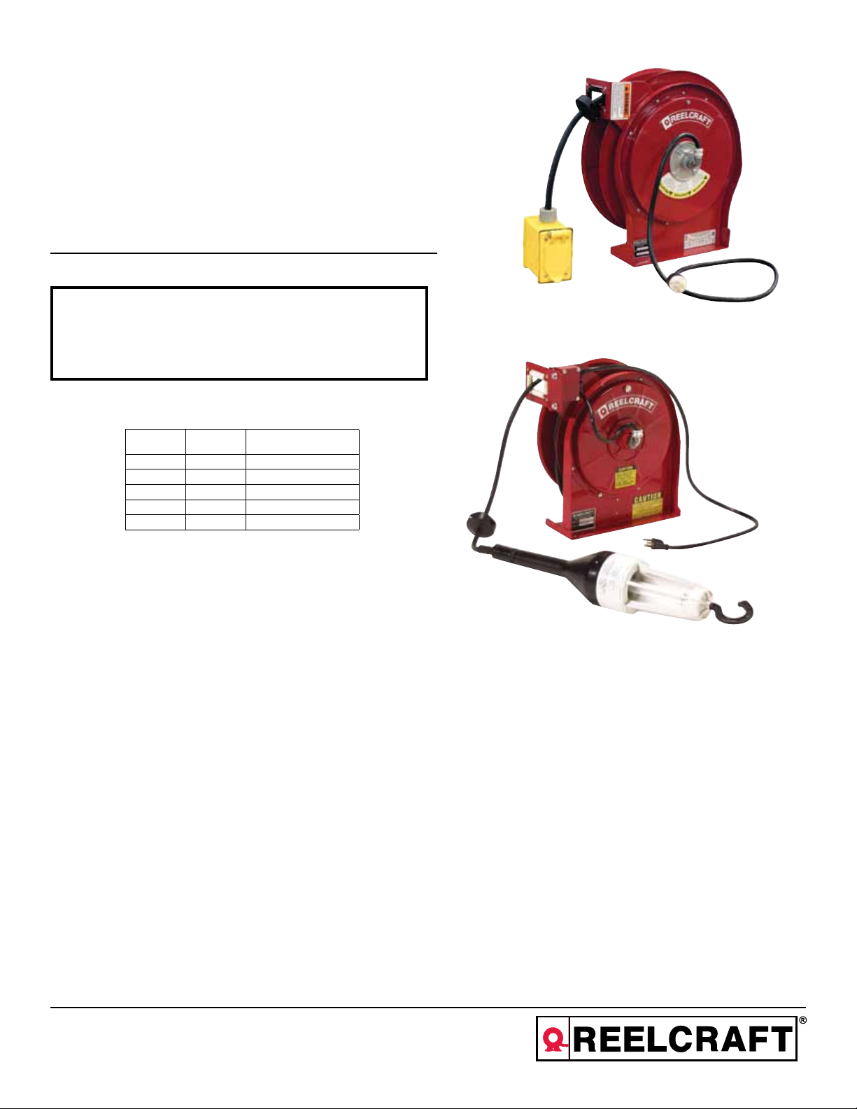
Operating Instructions
Series L 5000 Cord Reels
Model Numbers:
L 5000 L 5035 103 4 L 5550 123 3B L 5550 123 X
L 5400 L 5245 A 163 6X L 5550 123 7 L 5550 124 X
L 5500 L 5550 123 3 L 5550 123 7B L 5750 103 4
L 5700 L 5550 123 3A L 5550 123 7D L 5750 103 X
IMPORTANT
Read this manual carefully before installing, operating or
servicing this equipment.
Electrical Information
Voltage AMPS Frequency
125 13 60 HZ Single Phase
125 15 60 HZ Single Phase
600 16 60 HZ Single Phase
125 20 60 HZ Single Phase
125 30 60 HZ Single Phase
SAFETY
Personal injury and/or equipment damage may result if proper safety
precautions are not observed.
• Ensure that only a qualified electrician installs/services this
equipment.
•
• Ensure that power supply voltage does not exceed maximum
voltage rating of reel.
•
• Ensure that all electrical power is removed from reel before
servicing.
•
• A high-tension spring assembly is contained within the reel.
Exercise extreme caution.
•
• Check for frayed and/or broken wires before each use. Pull
electrical cord from reel by grasping the electrical cord itself,
not the work device.
•
• If an electrical malfunction should occur, remove power from
reel immediately.
Reelcraft Industries, Inc. • 2842 E Business Hwy 30, Columbia City, IN 46725
Ph: 800-444-3134 / 260-248-8188 • Fax: 800-444-4587 / 260-248-2605
Customer Service: 855-634-9109 • reelcraft@reelcraft.com • www.reelcraft.com
• Ensure that reel, electrical cord, and equipment being serviced
are properly grounded. Use an ohmmeter to check ground
continuity.
•
• If reel ceases to unwind or rewind, remove power immediately.
Do not pull or jerk on electrical cord!
•
• Treat and respect the reel as any other piece of machinery,
observing all common safety practices.
•
• All cord reels with flying leads must be hard wired into the
electrical circuit to ensure proper function.
•
WARNING: Even low voltage can cause irreparable damage or
death! Exercise extreme caution while operating or servicing this
equipment.
Form# 565-291 Rev: 11/2013
Page 2
Series L 5000 Cord Reels
Installation Instructions
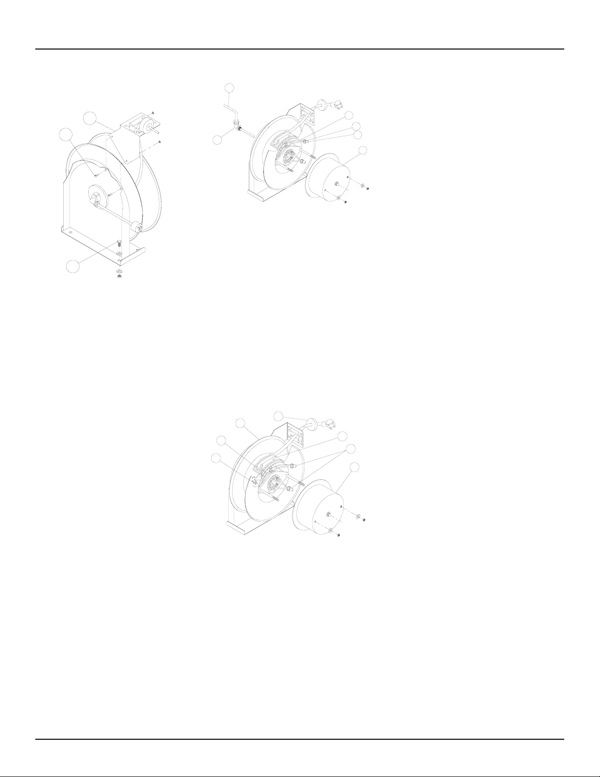
Mounting
2
1
3
CAUTION:
Unless reel was specified differently when
ordering, maximum installation height is 16
feet. Do not exceed this distance. Ensure
that only a qualified electrician installs/
services this equipment. Observe applicable
NEC, OSHA, and local codes when installing this equipment. Installation of GFCI cord
reels should be performed by a qualified and
licensed professional in accordance with local
building codes and applicable NEC standards.
1. Unpack and inspect the reel for damage.
Turn by hand to check for smooth operation. Check for completeness.
2. Configure reel for top, side or bottomwind (bottom-wind for constant tension
reels only) electrical cable dispensing by
removing bolts (1) securing guide arm
bracket (2).
3. Determine new guide arm bracket location and remove corresponding bolts.
Position guide arm bracket to reel and
replace bolts.
4. Position reel on floor, wall or ceiling.
Secure into place using four (customer
supplied) screws or bolts (3).
Installing the Input Electrical Cable:
30 AMP Models
WARNING:
Use only 10/3 cable for input wiring. Ensure
that application does not exceed electrical rating of reel. (See page 1 of this manual).
1
3
4
2
5
1. Feed input cable (1) through elbow (2)
and main shaft.
2. Screw elbow (2) into reel.
3. Connect input wires (3) and collector
ring wires (4) together using wire nuts
(5).
4. Assemble cover (6) to reel.
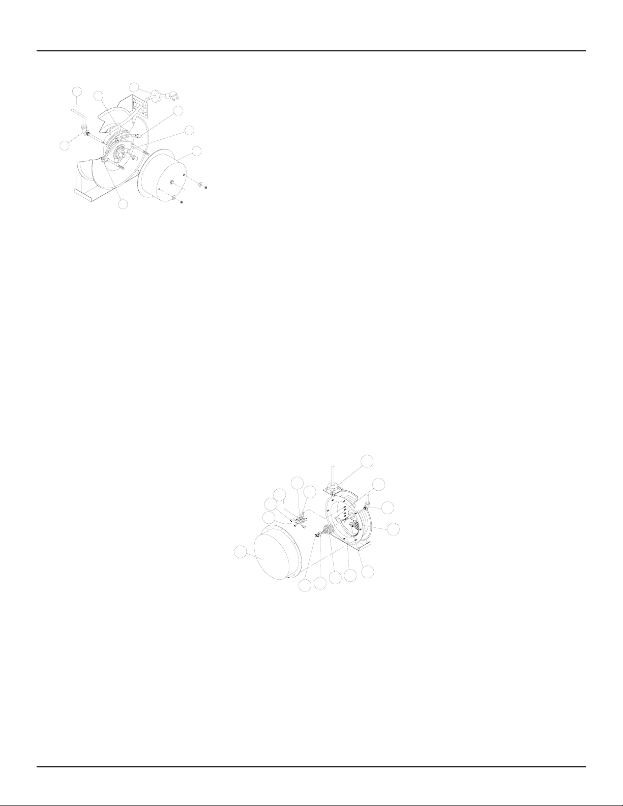
Installing the Output Electrical
Cable: 30 AMP Models
WIRE COLOR CODE
Black-Hot
White-Neutral
Green-Ground
7
10
12
WARNING:
Select output cable in accordance with power
requirement of apparatus to be supplied.
Ensure that application does not exceed
electrical rating of reel (see page 1 of this
manual). Use extreme caution, reel under tension. Avoid releasing latch mechanism.
1. Manually turn sheave (7) until spring is
tight, back off 2 turns, and latch.
2. Remove access cover (8).
3. Remove 6” of output electrical cable
outer jacket.
4. Route cable through guide arm and
U-clamp (9) then through cut-out (10)
13
9
11
8
in spool.
5. Tighten U-clamp (9).
6. Using wire nuts (11), connect output
electrical cable wires to collector assembly brush wires as indicated in illustra-
6
tion.
7. Connect ground wire of output electrical
cable to ground lug (12) located on inner
side of spool.
8. Using ohmmeter, check for ground faults.
9. Replace access cover (8). Release latch
and wind output electrical cable onto
reel.
10. Install cable bumper (13).
Adjusting the Spring Tension
If necessary, adjust spring tension on reel by
adding or removing wraps of electrical cord
from spool, one wrap at a time, until desired
tension is obtained. Add wraps to increase
tension. Remove wraps to decrease tension.
WARNING:
When adding wraps of electrical cord, be careful not to exceed the winding mechanism’s
spring capacity. Add just enough wraps of
cord to achieve the desired tension. Damage
to the winding mechanism will result if spring
is over-tightened. Always be aware of spring
tension on reel. Exercise extreme caution.
Troubleshooting Instructions:
30 AMP Models
Troubleshooting of the reel consists of
isolating a problem to a defective electrical
cord/work device, brush holder/brushes, or
collector assembly. Refer any other
discrepancies only to an authorized service
person or directly to Reelcraft.
WARNING:
The following procedure directs the techician
to take voltage measurements. Remember,
even low voltage is dangerous and can cause
personal injury or death. Exercise extreme
caution! Ensure that only a qualified electrician
installs/services this equipment.
Page 2
www.reelcraft.com
Page 3
Series L 5000 Cord Reels
4
9
5
13
14
11
8
12
1. Remove power from reel.
2. Remove cover (8) from reel.
3. Remove wire nuts (14) securing input
electrical cable wires to collector ring
assembly wires. Ensure that bare wires
do not contact each other or the reel
superstructure.
4. Apply power to reel.
5. Using voltmeter, check voltage between
black wire (hot) and white wire (neutral).
If voltage reading is correct (120 vac),
proceed to step 6. If voltage reading is
incorrect, replace input electrical cable
or Collector Ring Ass’y (refer to Service
Instructions).
Service Instructions:
30 AMP Models
WARNING:
Remove power from reel before performing any of the following procedures.
Replacing the Input Electrical
Cable
1. Remove access cover (8) from reel.
2. Remove wire nuts (14) connecting input
electrical cable (4) wires to collector ring
ass’y wires.
3. Unscrew elbow (5) from reel & pull out
input cable from main shaft & elbow.
4. Install replacement input cable (refer to
Installation Instructions).
Replacing the Output Electrical
Cord
WARNING:
Use extreme caution, reel under tension.
Avoid releasing latch mechanism.
1. Pull output electrical cable from reel until
cable is fully extended, then latch.
2. Remove access cover (8).
3. Remove wire nuts (11) securing output
electrical cable wires to collector assembly brush wires.
4. Remove output electrical cable ground
wire from ground lug (12).
5. Loosen U-clamp (9).
6. Remove output electrical cable.
7. Remove cable bumper (13).
8. Install replacement input electrical cable
(refer to Installation Instructions).
Troubleshooting Instructions:
20 AMP Models
Troubleshooting of the reel consists of
isolating a problem to a defective electrical
cord/work device, brush holder/brushes, or
collector assembly. Refer any other
discrepancies only to an authorized service
person or directly to Reelcraft.
WARNING:
The following procedure directs the technician
to take voltage measurements. Remember,
even low voltage is dangerous and can cause
personal injury or death. Exercise extreme
caution! Ensure that only a qualified electrican
installs or services this equipment.
3
13
12
10
14
1
11
7
15
6
1. If work device is either an incandescent
or fluorescent light, replace bulb with a
known good bulb. If this does not correct
the problem, proceed to step 2. If work
device is an electrical receptable, ensure
that tool or fixture connected to it is in
good working order. If it is, proceed to
step 2.
2. Remove power from reel.
3. Remove access cover (1).
4. Reapply power to reel.
5
8
2
9
4
5. Check for correct voltage (120 vac) at a
terminal strip (2). If voltage reading is
correct, replace output electrical device
(refer to Service Instructions). If voltage
reading is incorrect, proceed to step 6.
6. Remove power from reel.
7. Using ohmmeter, check continuity of
input electrical cord. If cord checks
good, proceed to step 8. If cord is faulty,
replace it (refer to Service Instructions).
Remove brush holder/brushes from
reel and inspect (refer to Service
Instructions). Replace defective components then proceed to step 9.
8. Reapply power to reel.
9. Check for correct voltage (120 vac) at
terminal strip (2).
10. If voltage reading is still incorrect,
replace defective collector assembly
(refer to Service Instructions).
11. Replace access cover (1).
Service Instructions:
20 AMP Models
Maintain reel by following the service
instructions given below. Refer all other
repairs, other than those listed, only to an
authorized service person or directly to
Reelcraft. Failure to do so can result in
personal injury and/or equipment damage and
may void the warranty.
www.reelcraft.com
Page 3
Page 4

Series L 5000 Cord Reels
Replacing the Output Electrical
Cord/Work Device
WARNING:
Remove power from reel before performing
any of the following procedures. Use extreme
caution, reel under tension. Avoid releasing
latch mechanism.
3
13
12
10
14
1
11
7
15
6
5
8
2
9
4
1. Pull output electrical cord from reel until
fully extended, then latch.
2. Remove output electrical cord bumper
(3).
3. Remove access cover (1).
4. Disconnect output electrical cord/work
device (4) at terminal strip (2).
5. Remove cable clamp.
6. Remove strain relief (5). Remove output
electrical cord/work device.
7. Install replacement electrical cord/work
device by reversing steps 2 through 5.
8. Release latch and rewind electrical cord
on reel.
9. Replace access cover (1) and cord bumper (3).
Replacing the Input Electrical Cord
WARNING:
All cord reels with GFCI receptacles must be
hard wired into the electrical circuits. Use of 2
or 3 prong plugs may cause a potential
malfunction of the GFCI receptacle.
3
13
12
10
14
1
11
7
15
6
5
8
2
9
4
1. Remove access cover (1).
2. Remove wire nuts (6) securing input
electrical cord to collector assembly (7).
3. Remove zip tie (not pictured), being careful to not damage wires.
4. Remove 90 degree elbow (8).
5. Remove input electrical cord.
6. Remove 11” of outer jacket from replacement input electrical cord (input electrical
cord wires must protrude a minimum of
6” from center of collector assembly).
7. Install replacement input electrical cord
by reversing steps 1 through 4.
8. Replace access cover (1).
Replacing the Brush Holder/Brushes
3
13
12
10
14
1
11
7
15
6
5
8
2
9
4
1. At terminal strip (2), remove wires
connecting brushes (9) to terminal strip.
2. Remove lock nuts (10) securing brush
holder (11) to reel. Relocate cable clamp
temporarily and remove brush holder.
3. Remove brushes (12) from brush holder
(11).
4. Install replacement brush holder/brushes
by reversing steps 1 through 3. Upon
completion of installation, adjust brush-to ring alignment by loosening nuts (13) and
sliding finger assembly (14).
Replacing the Collector Assembly
3
13
12
10
14
1
11
7
15
6
5
8
2
9
4
1. Remove access cover (1).
2. Remove wire nuts (6) securing input
electrical cord to collector assembly.
3. Remove zip tie (not pictured), being careful to not damage wires.
4. At terminal strip (2), disconnect wires (9)
connecting brushes (12) to terminal strip.
5. Remove lock nuts (10) securing brush
holder (11) to reel. Relocate cable clamp
temporarily and remove brush holder.
6. Remove coupling nut (15).
7. Remove collector assembly.
8. Install replacement collector assembly
by reversing steps 1 through 5. Upon
completion of installation, adjust brushto-ring alignment by loosening nuts (13)
and sliding finger assembly (14).
9. Replace access cover (1).
Page 4
www.reelcraft.com
Page 5

Series L 5000 Cord Reels
Operating Instructions
Autoswitch
ON
OFF
Operation
To operate Autoswitch reels, pull and retract
cable. When cable is fully retracted, the reel is
in the “OFF” position. As the cable is pulled
out, the guide arm pivots upward and the reel
is in the “ON” position.
Troubleshooting
Autoswitch
If reel fails to operate electrically, refer to
“Troubleshooting” instructions on page 5. If
problem persists, check switch using the
following steps.
Using an ohmmeter, check for continuity
between lines (1) and (2) while switch is in
the “ON” of “UP” position.
If continuity test fails, replace switch (3).
If continuity test passes, check for inlet cord
(4) damage.
Installation Instructions
Installing the Input Electrical Cable:
20 AMP Models
WARNING:
Use only 12/3 or 16/3 cable for input wiring.
Ensure that application does not exceed
electrical rating of reel (see page 1 of this
manual).
1
4
3
2
5
1. Feed input cable (1) through elbow (2)
and main shaft.
2. Screw elbow (2) onto reel.
3. Connect input wires (3) and collector ring
wires (4) together using wire nuts (5).
4. Take the provided zip tie (not pictured)
and zip tie the input cable wires together
closest to the slip ring.
5. Assemble cover (6) to reel.
6
10
6
7
1
8
4
3
9
5
2
1. Manually turn sheave (1) until spring is
tight, back off 2 turns and latch.
2. Remove access cover (2).
3. Remove 6” of output cable outer jacket
(3) and add fork terminals (4) to ends.
4. Route cable through strain relief (6), then
through cut out in spool (7).
5. Pull enough cable through hole for
roughly a 1/2 an inner wrap shown.
6. Connect output wires to terminal block
(8) as shown.
7. Connect ground wire to grounding stud
(9) as shown.
8. Using an ohmmeter check for ground
faults.
9. Take the provided cable clamp (not pictured) and attach it to the wire. Then take
the cable clamp and screw it down to the
right-most screw on the brush assembly
(with the brush assembly facing upward).
10. Replace cover (2).
11. Replace latch and wind cable onto reel.
12. Install cable bumper (10).
Service Instructions
Maintain reel by following the service
instructions given below. Refer all other
repairs, other than those listed, only to an
authorized service person or directly to
Reelcraft. Failure to do so can result in personal injury and/or equipment damage and
may void the warranty.
www.reelcraft.com
Installing the Output Electrical
Cable: 20 AMP Models
WARNING:
Select output cable in accordance with power
requirement of apparatus to be supplied.
Ensure that application does not exceed
electrical rating of reel (see page 1 of this
manual). Use extreme caution, reel under
tension. Avoid releasing latch mechanism.
Page 5
Page 6

Series L 5000 Cord Reels
Page 6
Dimensions - Size Index
1 2 3
A 14 1/2” 17 1/2” 17 1/2”
B 13 1/2” 16 1/2” 16 1/2”
C 9 3/4” 9 3/4” 9 3/4”
D 2 1/2” 2 1/2” 2 1/2”
E 10 1/2” 10 1/2” 12 1/2”
F 2 1/8” 2 1/8” 2 1/8”
www.reelcraft.com
Page 7

Series L 5000 Cord Reels
Item
#
1 Inlet Cord Assembly 1 None None None None None None 260630 602002
2 Connector, 90° Cord 1 S158-3 S261140 S261140 S158-3 S158-3 261140-1-C S261140 S261140
4 Screw, Set Pin 1 300006 300006 300006 300006 300006 300006 300006 300006
5 Lock Nut 10-32 22 S300011 (x7) S300011 S300011 S300011 S300011 (x7) S300011 S300011 (x20) S300011 (x20)
6 Snap Ring 1 300031 300031 300031 300031 (x2) 300031 300031 300031 300031
7 Spring Case Stud 1 S261360 S261360 S261360 S261360 S261360 S261360 S261360 S261360
8 Screw 10-32 x 1/2 2 300002 300002 300002 300002 300002 300002 300002 300002
9 Guide Arm and Roller 1 S500107 S500107 S500107 S500107 S500107 None S500107 S500107
10 Hose Bumper Assembly 1 A1-HR1004-3 A1-HR1004-A 1-HR1004 A1-HR1004-3 A1-HR1004-3 600927 1-HR1004 1-HR1004
11 Spring Arbor 1 S400017 S400017 S400017 S400017 S400017 S400017 S400017 S400017
12 Latch Cam 1 S500019 S500019 S500019 S500019 S500019 S500019 S500019 S500019
13 Disc, Sheave 1 500006 400006 None None 500006 400006 None None
14 Strain Relief 1 262181 260633 260697 262181 262181 260633 260697 260697
16 Split Lock Washer 3 902016 902016 902016 902016 902016 902016 902016 902016
17 Hex Bolt 1/4-20 3 S2-42 S2-42 S2-42 S2-42 S2-42 S2-42 S2-42 S2-42
18 Slip Ring and Brush 1 ** 602296 602296 ** ** 602296 602296 602296
19 Cover 1 ** 261723 None None None 261723 None None
20 Snap Ring 1 None S137-12 S140-13 None S137-12 S140-13 S140-13 S140-13
21 Wire Nut 3 * 260774 260774 ** ** 260500 260774 260774
22 Grounding Cord 1 None 600283 600283 None None 600241 600283 600283
23 Lock Washer 1 None S115-10 S115-10 None None S115-10 S115-10 S115-10
24 Quick Connect 1 None 260609 260609 None None 260609 260609 260609
25 Terminal Block 1 None 600205 600205 None None 600205 600205 600205
26 Sheave Assembly 1 602406 600254 None None 602406 600194-1 600281 None
27 Screw 10-32 x 3/8” 5 None 300001 300001 (x6) None None 300001 300001 (x6) 300001 (x6)
28 Latch Plate Spring 1 S400018 S400018 S400018 S400018 S400018 S400018 S400018 S400018
29 Screw 10-24 x 3/8” 1 None S32-136 None None None S32-136 None None
30 Screw 10-32 x 1” 1 300035 300035 300035 300001 300035 300035 300001 300001
31 Latch Bumper 1 S400021 S400021 S400021 S400021 S400021 S400021 S400021 S400021
32 Latch Plate Assembly 1 S400109 S400109 S400109 S400109 S400109 S400109 S400109 S400109
33 Latch Bushing 1 S400012 S400012 S400012 S400012 S400012 S400012 S400012 S400012
34 Base Assembly 1 500101 500101 None None 500101 500101 None None
35 Main Shaft 1 262462 262244 262244 262462 262462 262244 262244 262244
36 Spacing Washer 2 300034 300034 300034 300034 300034 300034 300034 300034
37 Drive Spring Assembly 1 S504240 S503755 S600050 S600050 S504240 S503755 S600050 S600050
38 Spring Case and Hub 1 S500103 S500103 S600094 S600094 S500103 S500103 S600094 S600094
39 Nut, Nyloc 1 S82-15 S82-15 S82-15 S82-15 S82-15 S82-15 S82-15 S82-15
40 Base Assembly 1 None None 600029 600029 None None 600029 600029
41 Disc, Sheave 1 None None 300006 260151 None None 260151 260151
42 Sheave Assembly 1 None None 600281 S602388 None None 600281 600281
43 Gasket 1 None None 260696 None None None 260696 260696
44 Cover 1 None None 261723 ** None None 261723 261723
45 Plug 50’, RV Plug 35’ 1 None None None None 602408 None None None
47 Single Outlet (Female) 1 None None None None None None 600282 602386
48
49 Autoswitch Assembly 1 None None None None None 600480 None None
50 Roller Plate Assembly 1 None None None None None 600342 None None
51 Switch Box 1 None None None None None 260780 None None
52 Inlet Cord Assembly 1 None None None None None 600472 None None
53 Switch 1 None None None None None 260775 None None
54 Guide Arm 1 None None None None None 600529 None None
55 Spring 1 None None None None None 260779 None None
56 Grounding Terminal 1 260675 None None 260675 260675 None None None
Dimension Size Index # - See page 6 1 1 2 3 1 1 2 2
Description
Fluorescent Lamp and
Cord Assembly
#
Req.
L 5000 L 5400 L 5500 L 5700 L 5035 103 4
1 None None None None None 600481 None None
L 5245 A
163 6X
L 5550 123 3
L 5550 123
3A
www.reelcraft.com
*Included in hardware kit #602048
**Included in hardware kit #602375
Page 7
Page 8

Series L 5000 Cord Reels
Item
#
1 Inlet Cord Assembly 1 602002 600564 602002 261165 262307 262328 None None
2 Connector, 90° Cord 1 S261140 S261140 S261140 S261140
4 Screw, Set Pin 1 300006 300006 300006 300006 300006 300006 300006 300006
5 Lock Nut 10-32 20 S300011 S300011 S300011 S300011 S300011 S300011 S300011 S300011
6 Snap Ring 1 300031 300031 300031 300031 300031 300031 300031 (x2) 300031 (x2)
7 Spring Case Stud 1 S261360 S261360 S261360 S261360 S261360 S261360 S261360 S261360
8 Screw 10-32 x 1/2 2 300002 300002 300002 300002 300002 300002 300002 300002
9 Guide Arm and Roller 1 S500107 S500107 S500107 S500107 S500107 S500107 S500107 S500107
10 Hose Bumper Assembly 1 1-HR1004 1-HR1004 1-HR1004 1-HR1004 A1-HR1004 A1-HR1004 A1-HR1004-3 A1-HR1004-3
11 Spring Arbor 1 S400017 S400017 S400017 S400017 S400017 S400017 S400017 S400017
12 Latch Cam 1 S500019 S500019 S500019 S500019 S500019 S500019 S500019 S500019
14 Strain Relief 1 260697 260697 260697 260697 260697 260697 260697 260697
15 Flange Shaft 1 602348 602348 602348 602348 602348 602349 602391 602391
16 Split Lock Washer 3 902016 902016 902016 902016 902016 902016 902016 902016
17 Hex Bolt 1/4-20 3 S2-42 S2-42 S2-42 S2-42 S2-42 S2-42 S2-42 S2-42
18 Slip Ring and Brush 1 602296 602296 602296 602296 602296 602297 602375 602375
20 Snap Ring 1 S140-13 S140-13 S140-13 S140-13 S140-13 S140-13 None None
21 Wire Nut 3 260774 260774 260774 260774 260774 260774 ** **
22 Grounding Cord 1 600283 600283 600283 600283 600283 600283 None None
23 Lock Washer 1 S115-10 S115-10 S115-10 S115-10 S115-10 S115-10 S115-8 (x4) S115-8 (x4)
24 Quick Connect 1 260609 260609 260609 260609 260609 260609 None None
25 Terminal Block 1 600205 600205 600205 600205 600205 600205 None None
27 Screw 10-32 x 3/8” 6 300001 300001 300001 300001 300001 300001 300001 300001
28 Latch Plate Spring 1 S400018 S400018 S400018 S400018 S400018 S400018 S400018 S400018
30 Screw 10-32 x 1” 1 300035 300035 300035 300035 300035 300035 300035 300035
31 Latch Bumper 1 S400021 S400021 S400021 S400021 S400021 S400021 S400021 S400021
32 Latch Plate Assembly 1 S400109 S400109 S400109 S400109 S400109 S400109 S400109 S400109
33 Latch Bushing 1 S400012 S400012 S400012 S400012 S400012 S400012 S400012 S400012
35 Main Shaft 1 262244 262244 262244 262244 262244 262397 262462 262462
36 Spacing Washer 2 300034 300034 300034 300034 300034 300034 300034 300034
37 Drive Spring Assembly 1 S600050 S600050 S600050 S600050 S600050 S600050 S600050 S600050
38 Spring Case and Hub 1 S600094 S600094 S600094 S600094 S600094 S600094 S600094 S600094
39 Nut, Nyloc 1 S82-15 S82-15 S82-15 S82-15 S82-15 S82-15 S82-15 S82-15
40 Base Assembly 1 600029 600029 600029 600029 600029 600029 600029 600029
41 Disc, Sheave 1 260151 260151 260151 260151
42 Sheave Assembly 1 600281 600281 600281 600281 600281 600281 S602388 S602388
43 Gasket 1 260696 260696 260696 260696 260696 260696 None None
44 Cover 1 261723 261723 261723 261723 261723 261723 ** **
45 Plug 50’, RV Plug 35’ 1 None None None None None None 602409 None
46 Dual GFCI Receptacle 1 None 602332-50 602255-50 602255-50 None None None None
47 Single Outlet (Female) 1 602451-50 None None None None None None None
56 Grounding Terminal 1 None None None None None None 260674 260675
57 Flying Lead 1 None None None None 602353-50 602475-50 None 602418
Dimension Size Index # - See page 6 2 2 2 2 2 2 3 3
Description
Req.
L 5550
#
123 3B
L 5550 123 7
L 5550
123 7B
L 5550
123 7D
L 5550 123 X L 5550 124 X L 5750 103 4 L 5750 103 X
262293
262294
260151 260151 260151 260151
262293
262294
S158-3
262293
262294
Page 8
*Included in hardware kit #602048
**Included in hardware kit #602375
www.reelcraft.com
 Loading...