

ReelCraft L 4050 163 1, L 4035 163 3, L 4050 162 2, L 4035 162 2, L 4035 163 3-RP Operating Instructions Manual
...
Operating Instructions
Series L 4000 Spring Driven Cord Reels
L 4035 163 1 L 4545 123 3 L 4545 123 7A L 4050 163 10
L 4050 163 1 L 4545 123 3-RP L 4545 123 7B L 4050 163 X
L 4035 162 2 L 4545 123 3A L 4035 163 8 L 4545 123 X
L 4050 162 2 L 4545 123 3A-RP L 4050 163 8 L 4000
L 4035 163 3 L 4545 123 3B L 4050 163 9 L 4100
L 4035 163 3-RP L 4035 A 163 5 L 4545 123 9 L 4500
L 4050 163 3 L 4050 A 163 5 L 4545 123 9G
L 4050 163 3-RP L 4545 123 7 L 4035 163 10
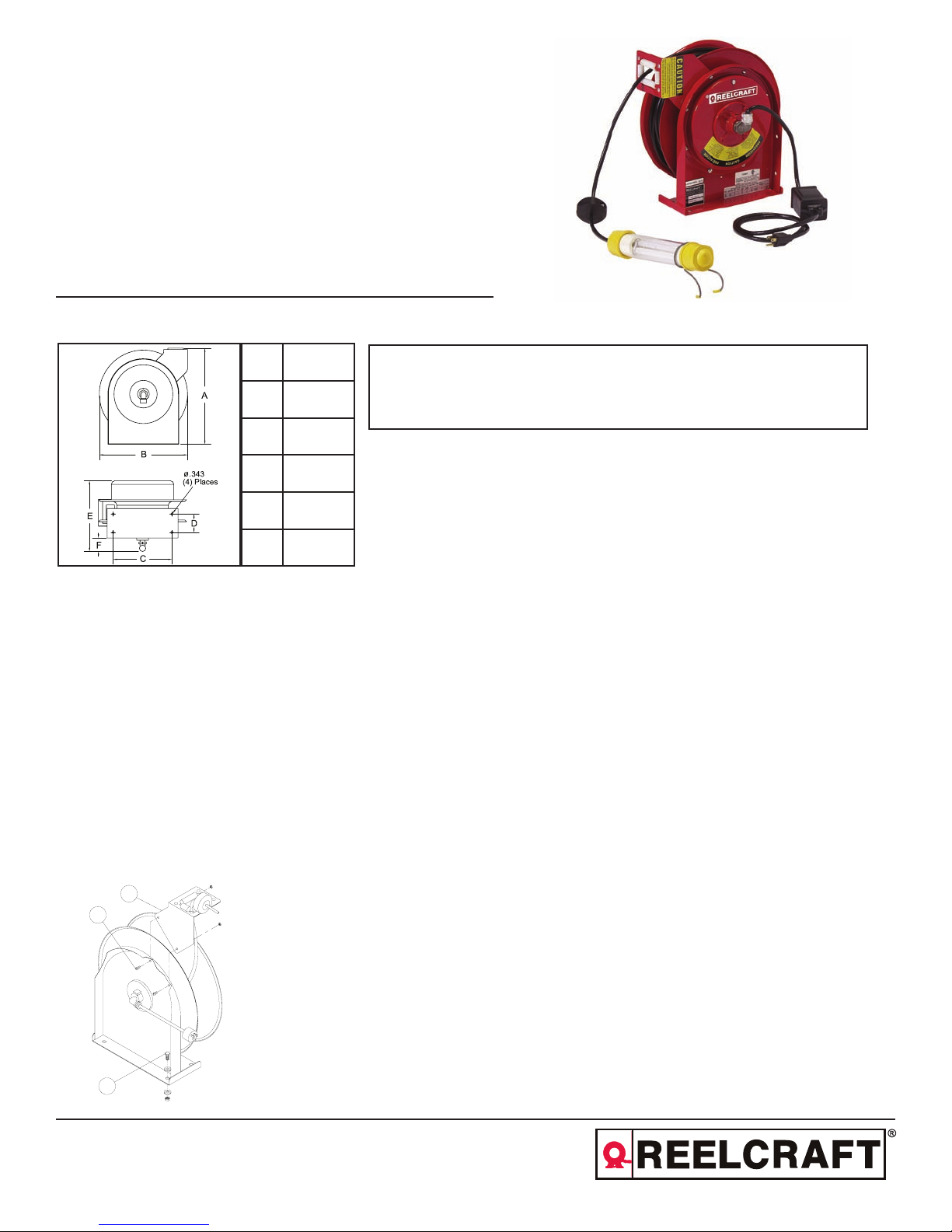
Dimensions
A 13 1/4”
B 12 5/8”
C 8”
D 2 1/2”
E 9 3/8”
F 1 3/4”
Safety Precautions
Personal injury and/or equipment damage may
result if proper safety precautions are not
observed.
• Ensure that only a qualified electrician
installs/services this equipment.
• Ensure that power supply voltage does not
exceed maximum voltage rating of reel.
• Ensure that reel is properly installed before
connecting to power supply.
• All cord reels with flying leads must be hard
wired to ensure proper function.
IMPORTANT
Read this manual carefully before installing, operating or
servicing this equipment.
WARNING: Even low voltage can cause irreparable damage or death!
Exercise extreme caution while operating or servicing this equipment.
• Ensure that all electrical power is removed
from reel before servicing.
• A high-tension spring assembly is
contained within the reel. Exercise extreme
caution.
• Check for frayed and/or broken wires before
each use. Pull electrical cord from reel by
grasping the electrical cord itself, not the
work device.
• If an electrical malfunction should occur,
remove power from reel immediately.
• Ensure that reel, electrical cord, and
equipment being serviced are properly
grounded. Use an ohmmeter to check
ground continuity.
• If reel ceases to unwind or rewind, remove
power immediately. Do not pull or jerk on
electrical cord!
• Treat and respect the reel as any other piece
of machinery, observing all common safety
practices.
Installation Instructions
2
1
3
Reelcraft Industries, Inc. • 2842 E Business Hwy 30, Columbia City, IN 46725
Ph: 800-444-3134 / 260-248-8188 • Fax: 800-444-4587 / 260-248-2605
Customer Service: 855-634-9109 • reelcraft@reelcraft.com • www.reelcraft.com
Mounting
CAUTION: Unless reel was specified differ-
ently when ordering, maximum installation
height is 16 feet. Do not exceed this distance.
Ensure that only a qualified electrician installs/
services this equipment. Installation of GFCI
cord reels should be performed by a qualified
and licensed professional in accordance with
building codes and applicable NEC standards.
1. Unpack and inspect reel for damage.
Turn by hand to check for smooth operation. Check for completeness.
2. Configure reel for top, side or bottomwind (bottom-wind for constant tension
reels only) electrical cord dispensing by
removing bolts (1), securing guide arm
bracket (2). Determine new guide arm
location and remove corresponding bolts.
Position guide arm bracket to reel and
replace bolts.
3. Position reel on floor, wall, or ceiling.
Secure into place, using four (customer
supplied) screws or bolts (3).
Form# 542-290 Rev: 6/2016
Series L 4000 Spring Driven Cord Reels
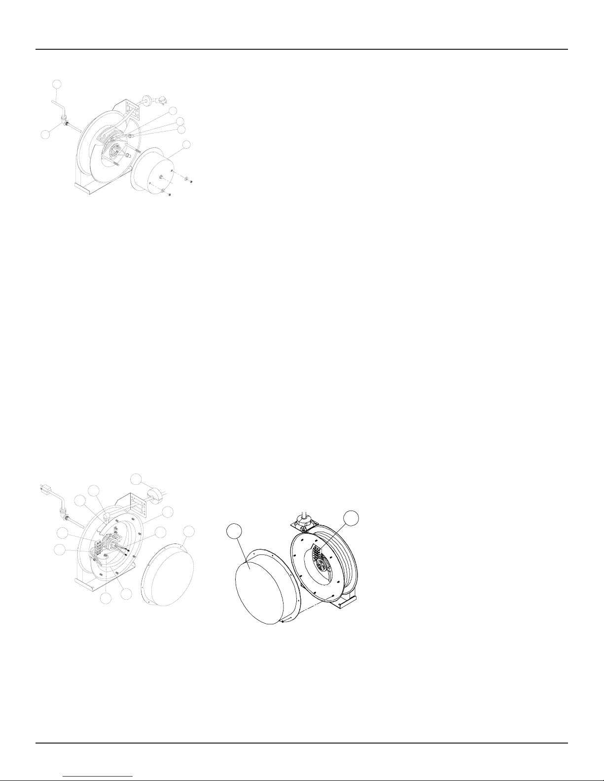
Installing the Input Electrical Cable
1
3
4
2
5
6
WARNING: Use only 12/3 or 16/3 cable for
input wiring. Ensure that application does
not exceed electrical rating of reel (refer to
page 1 of this manual). All cord reels with
GFCI receptacles must be hard wired into the
electrical circuit. Use of 2 or 3 prong plugs
may cause a potential malfunction of the GFCI
receptacle.
1. Feed input cable (1) through elbow (2)
and main shaft. Make sure that input
cable extends 6” from collector.
2. Screw elbow (2) into reel.
3. Connect input wires (3) and collector
ring wires (4) together using wire nuts
(5).
4. Take the provided zip tie (not pictured)
and zip tie the input cable wires together
closest to the slip ring.
5. Assemble cover (6) to reel.
Installing the Output
Electrical Cable
10
6
7
1
2
8
4
3
9
WARNING: Select output cable in accordance
with power requirement of apparatus to be
supplied. Ensure that application does not
exceed electrical rating of reel (refer to page
1 of this manual). Use extreme caution, reel
under tension. Avoid releasing latch mechanism.
1. Manually turn sheave (1) until spring is
tight, back off 2 turns, and latch.
5
2. Remove access cover (2).
3. Remove 6” of output cable outer jacket
(3) and add fork terminals (4) to ends.
4. Route cable through strain relief (6), then
through cut out in spool (7).
5. Pull enough cable through for roughly
1/2 an inner wrap as shown in the diagram.
6. Connect output wires to terminal block
(8) as shown.
7. Connect ground wire to grounding stud
(9) as shown.
8. Using Ohmmeter check for ground faults.
9. Take provided cable clamp (not pictured)
and attach it to the wire. Then take the
cable clamp and screw it down to the
brush assembly on the reel.
10. Replace cover (2).
11. Release latch and wind cable onto reel.
12. Install bumper stop (10).
Adjustments - Spring Tension
If necessary, adjust spring tension on reel by
adding or removing wraps of electrical cord
from spool, one wrap at a time, until desired
tension is obtained. Add wraps to increase
tension. Remove wraps to decrease tension.
WARNING: When adding wraps of electrical
cord, be careful not to exceed the winding
mechanism’s spring capacity. Add just enough
wraps of cord to achieve the desired tension.
Damage to the winding mechanism will result
if spring is over-tensioned. Always be aware
of spring tension on reel. Exercise extreme
caution.
Troubleshooting Instructions
2
1
Troubleshooting of the reel consists of isolating a problem to a defective electrical cord/
work device, brush holder/brushes, or collector assembly. Refer any other discrepancies only to an authorized service person or
directly to Reelcraft.
WARNING: The following procedure directs
the technician to take voltage measurements.
Remember, even low voltage is dangerous and
can cause personal injury or death. Exercise
extreme caution! Ensure that only a qualified
electrician installs/services this equipment.
1. If work device is either an incandescent
or fluorescent light, replace bulb with a
known good bulb. If this does not correct the problem, proceed to step 2. If
work device is an electrical receptacle,
ensure that tool or fixture connected to
it is in good working order. If it is, proceed to step 2.
2. Remove power from reel.
3. Remove access cover (1).
4. Reapply power to reel.
5. Check for correct voltage (120 V AC)
at terminal strip (2). If voltage reading is correct, replace output electrical cord/work device (refer to Service
Instructions). If voltage reading is incorrect, proceed to step 6.
6. Remove power from reel.
7. Using ohmmeter, check continuity of
input electrical cord. If cord checks
good, proceed to step 8. If cord is faulty,
replace it (refer to Service Instructions).
8. Remove brush holder/brushes from
reel and inspect (refer to Service
Instructions). Replace defective components then proceed to step 9.
9. Reapply power to reel.
10. Check for correct voltage (120 V AC) at
terminal strip (2). If voltage reading is
still incorrect, replace defective collector
assembly (refer to Service Instructions).
11. Replace access cover (1).
Service Instructions
Maintain reel by following the service instructions given below. Refer all other repairs,
other than those listed, only to an authorized
service person or directly to Reelcraft. Failure
to do so can result in personal injury and/or
equipment damage and may void the warranty
(refer to page 5 when referencing parts).
WARNING: Remove power from reel
before performing any of the following
procedures.
Page 2
www.reelcraft.com
Series L 4000 Spring Driven Cord Reels
Replacing the Output Electrical
Cord/Work Device
7
5
15
6
12
13
14
4
3
2
1
WARNING: Use extreme caution, reel under
tension. Avoid releasing latch mechanism.
1. Pull output electrical cord from reel until
fully extended, then latch.
2. Remove output electrical bumper stop
(7).
3. Disconnect output electrical cord/work
device (12) at terminal strip (10).
4. Remove strain relief (8). Remove output
electrical cord/work device.
5. Install replacement electrical cord/work
device by reversing steps 2 through 4.
6. Release latch and rewind electrical cord
on reel.
7. Replace access cover (1).
8
9
11
Replacing the Input Electrical Cord
WARNING: Use of 2 or 3 prong plugs on
cord reels equiped with GFCI receptacles may
cause a potential malfunction of the GFCI
receptacle.
1. Remove wire nuts (15) securing input
electrical cord to collector assembly (13).
2. Remove 90 degree elbow (9).
3. Remove input electrical cord.
4. Remove 11” of outer jacket from replacement input electrical cord (input electrical
cord wires must protrude a minimum of
6” from center of collector assembly).
5. Install replacement input electrical cord
by reversing steps 1 through 3.
6. Replace access cover (1).
Replacing the Brush
Holder/Brushes
1. At terminal strip (10), remove wires connecting brushes (11) to terminal strip.
2. Remove lock nuts (3) securing brush
holder (6) to reel. Relocate cable clamp
temporarily and remove brush holder.
3. Remove brushes (4) from brush holder
(6).
4. Install replacement brush holder/brushes
by reversing steps 1 through 3. Upon
completion of installation, adjust brush-
10
to-ring alignment by loosening nuts (5)
and sliding finger assembly (2).
Replacing the Collector Assembly
1. Remove wire nuts (15) securing input
electrical cord to collector assembly.
2. At terminal strip (10), disconnect wires
(11)connecting brushes (4) to terminal
strip.
3. Remove lock nuts (3) securing brush
holder (6) to reel. Relocate cable clamp
temporarily and remove brush holder.
4. Remove snap ring (14).
5. Remove collector assembly (13).
6. Install replacement collector assembly
by reversing steps 1 through 5. Upon
completion of installation, adjust brushto-ring alignment by loosening nuts (5)
and sliding finger assembly (2).
7. Replace access cover (1).
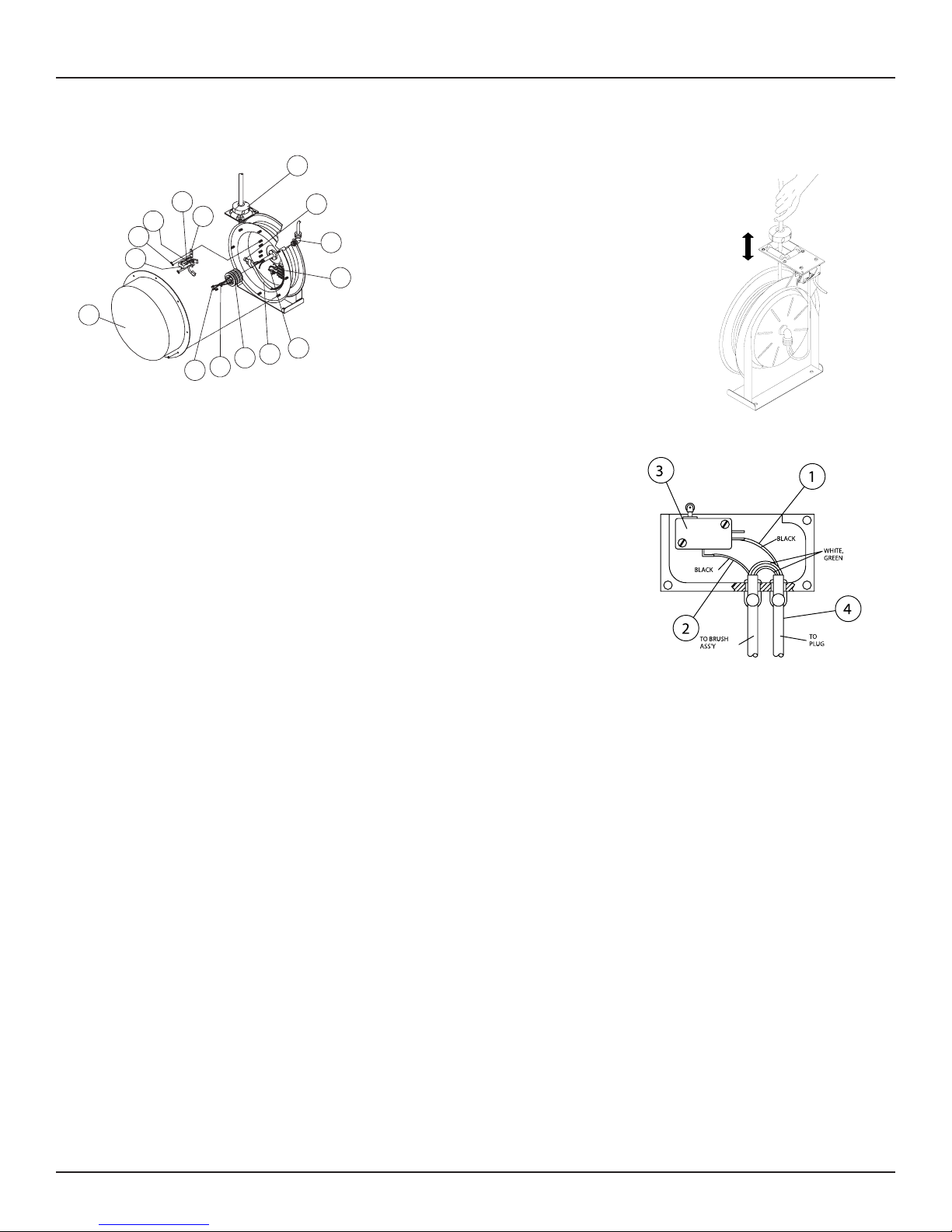
Autoswitch Operating Instructions
To operate Autoswitch reels, pull out and
retract cable as shown in the above diagram.
When cable is fully retracted, the reel is in the
“Off” position. As the cable is pulled out, the
guide arm pivots upward and the reel switches
to the “On” position.
Autoswitch Troubleshooting
Service Instructions
Maintain reel by following the service instructions given below. Refer all other repairs,
other than those listed, only to an authorized
service person or directly to Reelcraft. Failure
to do so can result in personal injury and/
or equipment damage and may void the warranty. If reel fails to operate electrically, refer
to troubleshooting instructions on page 2. If
problem persists, check switch using the following steps.
1. Using a ohmmeter, check for continuity
between lines (1) and (2), while switch is
in the “On” or “Up” position.
2. If continuity test fails, replace switch (3).
3. If continuity test passes, check for inlet
cord (4) damage.
ON
OFF
www.reelcraft.com
Page 3
 Loading...