

Reelcraft Hose Electrical Reel Cabinets User Manual

Operating Instructions
Hose / Electrical Reel Cabinets
1 Bank = #600367 2 Bank = #600178
APPLICATIONS
The Reelcraft 7000 Cabinet is designed for use
with Reelcraft 7000 C Series hose reels. By
using special adapter, part number 600230, the
7000 cabinet may be modified for use with 4000
and 5000 series reels.
INSTALLATION
The following installation procedure is applicable
for all 7000 Cabinet installations. If 4000 or
5000 Series hose reels are to be installed in
conjunction with the cabinet, perform all steps
of the following procedure (adapter, part number
600230, required). If 4000 Series cord reels are
to be installed in conjunction with the cabinet,
omit steps 6, 7, 9, and 11 of the following procedure. Before beginning, inspect packed materials
for shipping damage and completeness. Report
any discrepancies immediately.
CAUTION: Unless reel was specified differently
when ordering, maximum installation height
is 16 feet. Do not exceed this distance. Prior
to performing electrical maintenance (such
as removing and replacing the work device to
facilitate routing of the cord through the guide
roller assembly), ensure that all power has been
removed from reel. Consult manual of instructions accompanying reel for details.
1. Assemble beam clamp assembly by inserting spring nuts (6) into channel support
(8). Position beam clamps (5) and secure
into place with 1/2” bolts (4). Repeat this
step for each beam clamp assembly before
proceeding to next step.
2. Position beam clamp assembly to upper
mounting channel (1). Secure into place
with 1/2” bolts (7), spacers (9), and
locknuts (16). Repeat step for each beam
clamp assembly before proceeding to next
step.
3. Position upper mounting channel (1) to “I”
beam. Push beam clamps (5) inward until
they fully engage “I” beam flange. Tighten
1/2” bolts (4) to secure.
4. Position vertical channel (11) to upper
mounting channel (1) and secure into
place with four 5/16” bolts (10) and locknuts (10). Repeat step for opposite end of
bank.
NOTE: 4 bank models employ a vertical channel
in the center.
5. Position lower channel (15) to vertical
channels (11) and secure into place with
5/16” locknuts (14).
6. Apply pipe thread sealant to elbow swivel
union (17). Thread elbow swivel union
into inlet main shaft (19) of reel. Repeat
step for each reel before proceeding to next
step.
7. Thread connecting hose fitting (25) into
elbow swivel union (17). Tighten securely.
Repeat step for each reel before proceeding
to next step.
NOTE: If 4000 or 5000 Series reels are
being installed, special adapter 600230 must be
installed to reel before proceeding to next step.
Perform special adapter installation in accordance with diagram.
8. Position reel (26) to upper mounting channel (1). Secure into place with 3/8” bolts
and locknuts (27). Route 2’ connecting
hose (2) (or power cord in the case of
4000 cord reels) through upper mounting
channel (1) via 1-14” cutout (3). Repeat
step for each reel before proceeding to next
step.
9. Adjust spring tension of reel by pulling
hose from reel sheave until sheave has
turned three complete turns and then latch
reel in position. While reel is still latched,
manually rewrap hose on reel. Do not
release latch until step 10 of this procedure
has been completed. Repeat step for each
reel before proceeding to next step.
*See note below.
NOTE: In the following step, if a 4000 cord
reel is being installed, the output device and
bumper must be removed to facilitate routing
of the cord through the guide roller assembly.
Consult manual that accompanies each reel for
removing these items. *See note.
10. Route reel output hose (22) (or cord
in the case of 4000 cord reels)
through guide roller assembly (21) in
lower channel (15). When desired
length protrudes from lower channel,
install bumper (20) (do not install
output control device at this time).
Repeat step for each reel in bank
before proceeding to next step.
NOTE: For servicing, it is recommended that a
shut-off device be installed between the reel and
supply.
11. Flush piping system of contaminants.
Connect supply side plumbing, then pressurize system. Check system for leaks.
Shut off ball valves and relieve pressure.
Repeat step for each reel in bank before
proceeding to next step.
12. Install output control device.
13. Position wrapper (23) to assembly and
secure into place with clip (24). Repeat
step for each wrapper before proceeding to
next step.
14. Position end panel (13) to assembly and
secure into place using four 8-32 self-tapping screws (12). Repeat step for opposite
end of bank.
* If needed, adjust spring tension of reel
by adding or removing wrap of hose
from the spool, one wrap at a time,
until desired tension is obtained. Add
wraps to increase tension. Remove
wraps to decrease tension.
Reelcraft Industries, Inc. • 2842 E Business Hwy 30, Columbia City, IN 46725
Ph: 800-444-3134 / 260-248-8188 • Fax: 800-444-4587 / 260-248-2605
Customer Service: 855-634-9109 • reelcraft@reelcraft.com • www.reelcraft.com
Form# 1181-1205 Rev: 8/2014
Hose / Electrical Reel Cabinets
Page 2
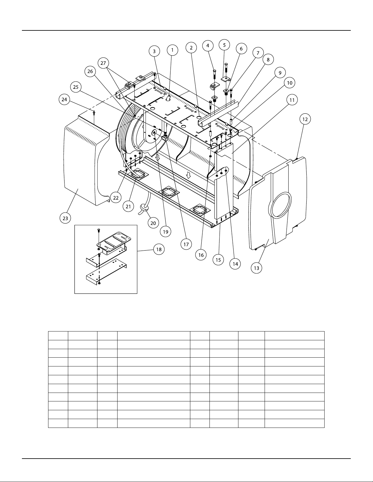
Item # Part # # Req. Description Item # Part # # Req. Description
1 262017 1 Upper Channel (1 bank) 13 260471 2 End Panel
1 262018 1 Upper Channel (2 bank) 14 S85-7 16 5/16-18 Nyloc Nut
4 S2-87 4 1/2-13 x 1 1/2” Hex Cap Screw 15 600369 1 Lower Channel (1 bank)
5 260477 4 Beam Clamp 15 600176 1 Lower Channel (2 bank)
6 260478 4 Spring Clamp Nut 16 S281-8 4 1/2-13 Hex Nut
7 S2-88 4 1/2-13 x 1 3/4” Hex Cap Screw 18 600230 2 (1 bank) Adapter
8 260476 2 Support Channel 23 260473 2 (1 bank) Wrapper
10 S2-52 8 5/16-18 x 5/8” Hex Cap Screw 23 260473 4 (2 bank) Wrapper
11 260549 2 Vertical Channel 24 S282-88 4 (1 bank) Self-Tapping Screw
12 S282-88 8 Self-Tapping Screw 24 S282-88 8 (2 bank) Self-Tapping Screw
www.reelcraft.com
 Loading...