

ReelCraft FSD13000 OLP118, SD14035 OLP118, SD13050 OLP118, SD13000 OLP118, FSD14035 OLP118 Operating Instructions Manual
...Page 1
Operating Instructions
Series SD10000 Spring Driven Reels
SD13050 OLP118 SD13000 OMP118
SD13000 OLP118 FSD13050 OLP118
SD14035 OLP118 FSD13000 OLP118
SD14050 OLP118 FSD14035 OLP118
SD14000 OLP118 FSD14050 OLP118
SD14005 OLP118 FSD14000 OLP118
SD13050 OMP118 FSD14005 OLP118
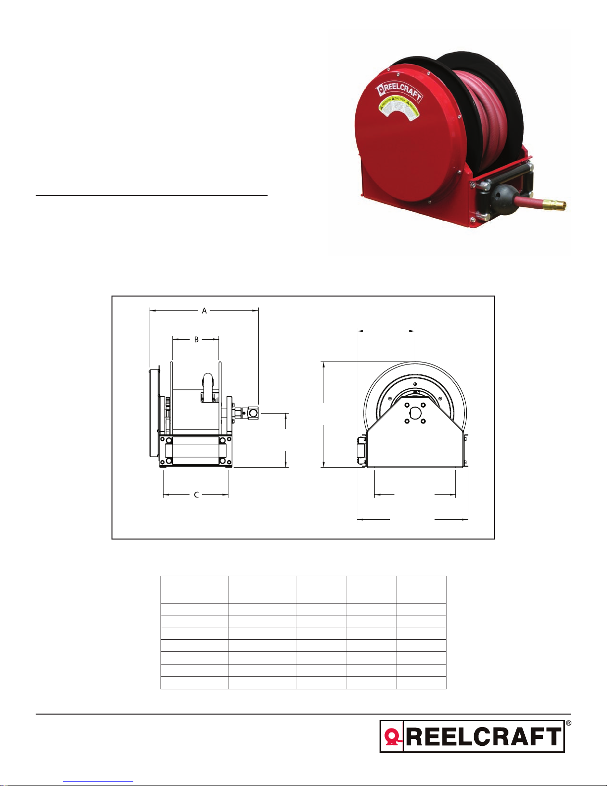
Dimensional Data
SD13050 OLP118
254 mm
238 mm
NOTE: (4) 12.7mm DIAMETER MOUNTING HOLES
Model
w/ hose
SD13050 OLP SD13000 OLP 476 mm 203 mm 286 mm
SD14035 OLP SD14000 OLP 476 mm 203 mm 286 mm
SD14050 OLP SD14005 OLP 527 mm 254 mm 337 mm
FSD13050 OLP FSD13000 OLP 476 mm 203 mm 286 mm
FSD14035 OLP FSD14000 OLP 476 mm 203 mm 286 mm
FSD14050 OLP FSD14005 OLP 527 mm 254 mm 337 mm
SD13050 OMP SD13000 OMP 476 mm 203 mm 286 mm
Model
w/o hose
464 mm
356 mm
486 mm
A B C
Reelcraft Industries, Inc. • 2842 E Business Hwy 30, Columbia City, IN 46725
Ph: 800-444-3134 / 260-248-8188 • Fax: 800-444-4587 / 260-248-2605
Customer Service: 855-634-9109 • reelcraft@reelcraft.com • www.reelcraft.com
Form# R1222-611 Rev: 9/2017
Page 2

Series SD10000 Spring Driven Reels
Safety
Read all instruction manuals, tags, and labels before operating this equipment. Personal injury and/or equipment damage
may result if proper safety precautions are not observed.
• This hose reel is for professional use only. Use the hose reel only for its intended purposes. If you are unsure call
your Reelcraft distributor.
• Check the hose reel and related equipment daily. Repair or replace worn or damaged parts immediately.
• Do not alter or modify this hose reel in any way. Use only genuine Reelcraft parts and accessories.
• Ensure that the hose reel is securely mounted before connecting the input and output hoses.
• Ensure that the reel, hose, and equipment being serviced are properly grounded. Use an ohmmeter to check ground
continuity.
• Before connecting the hose reel to the supply line, ensure that the pressure does not exceed the maximum pressure
of the lowest rated component within the system.
• Only use fluids, gases or solvents that are compatible with the exposed parts of the hose reel.
• If a leak occurs in the hose or reel, relieve the system pressure immediately. Bleed the fluid or gas pressure before
servicing the hose reel.
• A high tension drive spring in contained within the hose reel. Exercise extreme caution.
• If the hose reel ceases to unwind or rewind, relieve the system pressure immediately. Do not pull or jerk on the hose.
• Be aware of machinery and personnel in the work area. Route hoses away from traffic areas, sharp edges, moving
parts, and hot surfaces.
• Pull the hose from the reel by grasping the hose itself, not the control valve.
• Treat and respect the hose reel as you would any other piece of machinery, observing all common safety practices.
• Never allow hose to retract unassisted, always walk the hose back to the reel until the bumper engaged the guide
roller. Failure to do so can result in damage to the hose, hose reel and any surrounding equipment or personnel.
Warnings
Hazardous fluid or toxic fumes can cause serious injury or death if inhaled, swallowed, splashed in the eyes, or splashed
on the skin.
• Know the specific hazards of the fluid you are using.
• Store hazardous fluid in an approved container. Dispose of hazardous fluid according to all local, state and national
guidelines.
• Always wear protective eyewear, gloves, clothing, and a respirator as recommended by the fluid and solvent manufacturer.
Improper grounding, poor ventilation, open flames, or sparks can cause a hazardous condition and result in a fire or explosion and serious injury.
• For fueling applications, be sure the entire fluid system is properly grounded. The hoses installed with these hose
reels must be electrically conductive. The hose reel is grounded by connecting electrically conductive supply hoses to
a properly grounded system.
• If there is any static sparking or you feel an electric shock while using this equipment, stop dispensing immediately.
Do not use the equipment until you identify and correct the problem.
• Provide fresh air ventilation to avoid the buildup of flammable fumes from solvents or the fluid being dispensed.
• Keep the dispensing area free of debris, including solvent, rags, and spilled gasoline.
• Do not smoke while dispensing flammable fluids.
Page 2
www.reelcraft.com
Page 3
Series SD10000 Spring Driven Reels
Installation Instructions
Unless the hose reel was specified differently when ordering, the maximum installation height is 4.8 meters. Do not exceed this distance. This reel is of a compact design and is intended for mounting where the operator can guide the hose
onto the reel to avoid piling in any one area on the spool. Ceiling mounting is not recommended.
1. Unpack and inspect the hose reel for damage. Turn by hand to check for smooth operation. Check for completeness.
2. Secure the hose reel into place using 4 customer supplied bolts. Hose reel has 4 – 13mm diameter holes for mount-
ing. Secure the hose reel with a 10mm – 13mm bolts with washers.
Installing the Input Hose
Ensure that the supply line pressure does not exceed the maximum working pressure of the hose reel. Apply pipe thread
sealant to all threads. Use a flexible hose connection at the input connection. Do not use rigid plumbing.
1. Connect supply line hose (inlet hose) to the swivel as indicated in Fig. 1.
Installing the Output Hose
Warning: Use extreme caution; reel under tension. Avoid releasing latch mechanism. Apply pipe thread sealant to
all threads.
1. Relieve the pressure and bleed the line of all fluid. It is recommended that the supply line be removed from the supply
source to eliminate the possibility of pressurized fluid injuries and/or accidental spills.
2. Ensure that the hose reel has been mounted securely, following the steps listed above under Installation Instructions.
3. Place a piece of tape on the side of the reel flange as a visual reference point for counting spool rotations.
4. Unlatch the hose reel spool, and allow it to slowly rotate until all the spring tension has been released. Then rotate the
spool in the direction of the arrow shown in Fig. 1 to achieve the proper amount of spring tension for the hose you are
installing. Important: Release the reel only at points where it is securely latched. See the chart below for the proper
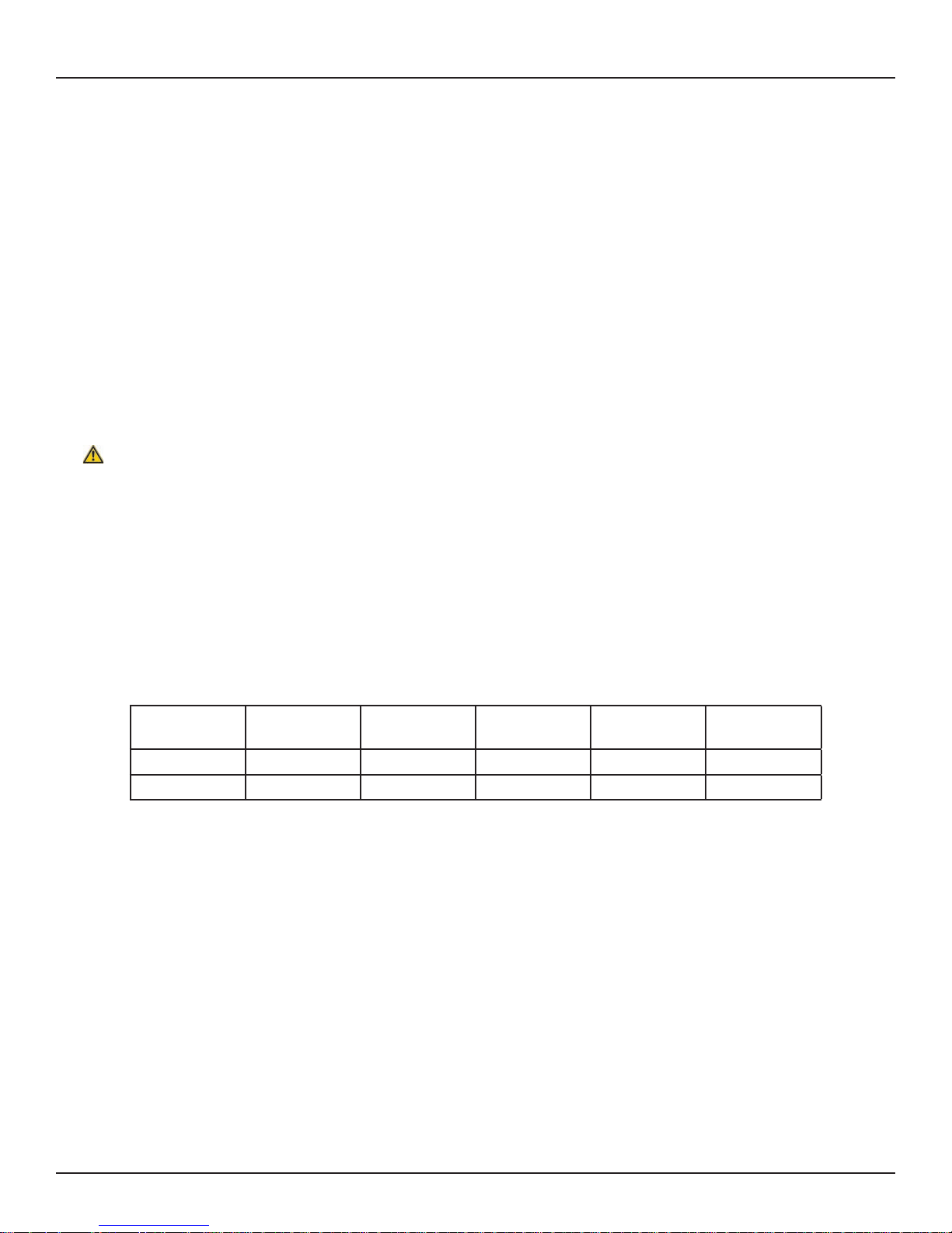
number of turns for your length of hose.
Hose I.D. Hose Length
Number of
Turns
Hose I.D. Hose Length
Number of
Turns
19 mm 11 m 13 25 mm 11 m 12
19 mm 15 m 17 25 mm 15 m 16
5. As a safety precaution, attach a C-clamp to the reel flange, as shown in Fig. 1, to help prevent the spool from uninten-
tionally becoming unlatched and spinning freely.
6. Uncoil and extend the new hose, and loosely install the bumper stop near the outlet end of the hose.
7. Attach the other end of the new hose to the gooseneck, securing it with pipe sealant compatible with the fluids being
used in the hose reel.
8. Remove the C-clamp from the reel flange.
9. Pull the hose firmly enough to release the latch, and then slowly allow the hose to retract.
10. Ensure that the hose can be pulled out all the way and that it fully retracts. If it does not pull out or retract properly,
see Adjusting Spring Tension on the next page.
11. Position the bumper stop so that the hose extends far enough for all operators to reach the dispensing valve.
12. Pressurize the reel assembly and check all connections for leaks. Repair any connections showing signs of leakage.
www.reelcraft.com
Page 3
Page 4

Series SD10000 Spring Driven Reels
Fig. 1
Adjusting Spring Tension
If the hose cannot be pulled all the way out, or if it does not retract all the way back onto the hose reel, you may need to
adjust the spring tension. To do so follow these steps:
1. Relieve the pressure and bleed the line of all fluid. It is recommended that the supply line be removed from the supply
source to eliminate the possibility of pressurized fluid injuries and/or accidental spills.
2. Pull the hose out and engage the latch.
3. Remove the dispensing valve (not shown) and bumper stop.
4. Pull the loose end of the hose back in through the hose rollers, and manually wrap the hose onto the reel.
5. Rotate the reel in the direction of the appropriate arrow shown in Fig. 2, keeping the hose wrapped on the reel.
6. Check the spring tension after each rotation. The hose must pull out and retract fully.
7. Repeat steps 4 and 5 until you have the proper amount of spring tension.
Caution: Do not increase the spring tension to the point that the spring winds up tightly before the hose is fully extended. A spring that is wound up too tightly stops the reel from rotating before the hose is fully extended, which puts
excessive strain on the hose and reel drive spring and could damage the reel.
8. Reroute the hose through the hose rollers, and reinstall the bumper stop and dispensing valve
Page 4
www.reelcraft.com
Page 5

Series SD10000 Spring Driven Reels
Fig. 2
Service Instructions
Spring Canister
To replace the spring canister, follow the steps below. Do not attempt to service the spring inside the spring canister.
Warning: The only service you should perform on the reel spring is replacing the spring canister. The spring is under
extreme tension and could be propelled out of the opened canister and cause serious injury.
1. Relieve the pressure and bleed the line of all fluid. It is recommended that the supply line be removed from the supply
source to eliminate the possibility of pressurized fluid injuries and/or accidental spills.
2. Remove dispensinge valve and bumper stop.
3. Unlatch reel and let the reel unwind fully to a free state before beginning disassembly. Do not allow the reel to unwind
unassisted. You risk damage to the hose threads, reel and personnel.
4. Remove the four 1/4”-20 nyloc nuts holding the spring and case assembly to the side frame.
5. Pull the spring and case assembly free from the side frame as shown in Fig.3.
6. Locate the new spring case and take note of the location of the “hook” on the end of the spring as shown in Fig.4.
7. Attach new spring and case assembly to side of the reel aligning the female hook of the drive spring to the male hook
on the arbor.
8. Replace four 1/4”-20 nyloc nuts and tighten securely.
9. Follow adjusting spring tension instructions above to properly tension the spring for your application after replacing
the spring.
www.reelcraft.com
Page 5
Page 6

Series SD10000 Spring Driven Reels
Fig. 3
Fig. 4
A
Page 6
www.reelcraft.com
Page 7

Series SD10000 Spring Driven Reels
Fluid Path Static Seal
Your hose reel is suited to be used with Air, Water, Oil, and Various Fuels. If a substance incompatible with the seal inside
the fluid path is pumped through the reel, the o-ring seal between the gooseneck and spindle may degrade and cause the
fluid path to leak. Verify with Reelcraft Engineering Department for hose reel compatibility with questionable substances.
If a leak should occur, contact Reelcraft to establish proper o-ring replacement and follow the steps below for o-ring replacement.
1. Relieve the pressure and bleed the line of all fluid. It is recommended that the supply line be removed from the supply
source to eliminate the possibility of pressurized fluid injuries and/or accidental spills.
2. Pull the hose assembly completely from the spool and latch the reel.
3. Attach a C-clamp to the reel flange to help prevent the reel from unintentionally becoming unlatched and spinning
freely.
4. Remove the outlet hose from the gooseneck (optional).
5. Remove the four bolts attaching the gooseneck to the spindle.
6. Remove the gooseneck and o-ring from the fluid path spindle. Check the o-ring groove for debris and remove any re-
sidual fluid that may be present. All surfaces of the gooseneck and spindle should be clean and free of debris.
7. Replace appropriate o-ring by placing it in the groove of the spindle.
8. Replace the gooseneck and secure it in place with four socket head cap screw.
Fig. 5
www.reelcraft.com
Page 7
Page 8

Series SD10000 Spring Driven Reels
Parts Drawing
Page 8
www.reelcraft.com
Page 9

Series SD10000 Spring Driven Reels
Parts Common to all Models
Item No. Part No. No. Req’d Description Item No. Part No. No. Req’d Description
2 262526 1 Latch ratchet 26 S44-6 4 Machine screw
3 260399-3-35 2 Spool flange 27 S140-34 1 Snap ring
4 262525-35 1 Head insert 29 300007 1 Snap ring
6 S280-8 1 Hex flange nut 30 261274 1 Spring arbor
7 300107 2 Lock nut 31 261275 1 Spring arbor key
8 262530 1 Latch pawl stud 32 S140-34 1 Snap ring
9 262118 1 Latch pawl 33 602453 1 Side frame & stud assembly
10 S140-6 1 Snap ring 35 S44-10 8 Machine screw
11 1-114901-2 1 Wear washer 36 S281-6 8 Hex flange nut
12 261616 1 Torsion spring 37 261304 2 Bearing flange
13 262529 1 Latch pawl bracket 38 261305 2 Sealed ball bearing
15 262455-1NPT 1 Fluid path gooseneck 39 262527 1 Side frame (inlet side)
17 S85-7 1 Nylock nut 40 S140-34 1 Snap ring
18 S85-7 8 Nylock nut 41 S600682 1 Swivel assembly
19 S44-2 4 Machine screw 42 S44-2 4 Machine screw
20 262520 1 Fluid path spindle 43 300107
21 S376-59 1 Machine screw 44 S44-10 4 Machine screw
22 S200-324 1 O-ring 45 S270014 4 Guide roller post
23 S7-51 4 Socket head cap screw 47 270110-3.000 2 Guide roller pin
24 S281-6 4 Hex flange nut 49 262436-2.468 2 Guide roller
25 S390030-1 4 Spacer 51 300070 4 Nyloc nut
8 Lock nut
Model Specific Parts - Air / Water Dispensing
Item
No.
1 Drive shaft 1 262536-8 262536-8 262536-8 262536-8 262536-10 262536-10
5 Tie rod 4 260402-170 260402-170 260402-170 260402-170 260402-140 260402-140
14 Drum 1 262524-8-35 262524-8-35 262524-8-35 262524-8-35 262524-10-35 262524-10-35
16 Reducing bushing 1 270025 270025 NONE NONE NONE NONE
28 Spring & case assembly 1 S602455-1 S602455-1 S602455-1 S602455-1 S602455-1 S602455-1
34 Tie plate 1 262532-8 262532-8 262532-8 262532-8 262532-10 262532-10
46 Guide roller pin 2 270110-8.750 270110-8.750 270110-8.750 270110-8.750 270110-10.750 270110-10.750
48 Guide roller 2 262436-8.218 262436-8.218 262436-8.218 262436-8.218 262436-10.218 262436-10.218
50 Tie plate 1 262531-8 262531-8 262531-8 262531-8 262531-10 262531-10
N/A Hose assembly 1 NONE 601034-50 NONE 601027-35 NONE S601027-50
N/A Bumper stop assembly 1 NONE 3-HR1005 NONE 4-HR1005 NONE 4-HR1005
--- Maximum pressure 500 PSI 250 PSI 500 PSI 250 PSI 500 PSI 250 PSI
--- Maximum temperature 210 °F 150 °F 210 °F 150 °F 210 °F 150 °F
Description
No.
Req’d
SD13000
OLP118
SD13050
OLP118
SD14000
OLP118
SD14035
OLP118
SD14005
OLP118
SD14050
OLP118
Model Specific Parts - Oil Dispensing
Item
No.
1 Drive shaft 1 262536-8 262536-8
5 Tie rod 4 260402-170 260402-170
14 Drum 1 262524-8-35 262524-8-35
16 Reducing bushing 1 300055 300055
28 Spring & case assembly 1 S602455-2 S602455-2
34 Tie plate 1 262532-8 262532-8
46 Guide roller pin 2 270110-8.750 270110-8.750
48 Guide roller 2 262436-8.218 262436-8.218
50 Tie plate 1 262531-8 262531-8
N/A Hose assembly 1 NONE 601037-50
N/A Bumper stop assembly 1 NONE 3-HR1005
--- Maximum pressure 3000 PSI 1250 PSI
--- Maximum temperature 210 °F 210 °F
Description
No.
Req’d
SD13000
OMP118
SD13050
OMP118
www.reelcraft.com
Page 9
Page 10

Series SD10000 Spring Driven Reels
Item
No.
1 Drive shaft 1 262536-8 262536-8 262536-10 262536-8 262536-8 262536-10
5 Tie rod 4 260402-170 260402-170 260402-140 260402-170 260402-170 260402-140
14 Drum 1 262524-8-35 262524-8-35 262524-10-35 262524-8-35 262524-8-35 262524-10-35
16 Reducing bushing 1 270025 270025 None None None None
28 Spring & case assembly 1 S602455-1 S602455-1 S602455-1 S602455-1 S602455-1 S602455-1
34 Tie plate 1 262532-8 262532-8 262532-10 262532-8 262532-8 262532-10
46 Guide roller pin 2 270110-8.750 270110-8.750 270110-10.750 270110-8.750 270110-8.750 270110-10.750
48 Guide roller 2 262436-8.218 262436-8.218 262436-10.218 262436-8.218 262436-8.218 262436-10.218
50 Tie plate 1 262531-8 262531-8 262531-10 262531-8 262532-8 262531-10
N/A Hose assembly 1 None S600160-2 None S600451-35 None S600451-50
N/A Bumper stop assembly 1 None 3-HR1005 None 4-HR1005 None 4-HR1005
--- Maximum pressure 500 PSI 50 PSI 500 PSI 50 PSI 500 PSI 50 PSI
--- Maximum temperature 210 °F 150 °F 210 °F 150 °F 210 °F 150 °F
Description
No.
Req’d
Model Specific Parts - Fuel Dispensing
FSD13000
OLP118
FSD13050
OLP118
FSD14000
OLP118
FSD14035
OLP118
FSD14005
OLP118
FSD14050
OLP118
Page 10
www.reelcraft.com
 Loading...