

Page 1
Operating Instructions
Series FF9000 Spring Driven Hose Reels
Low Pressure Model Numbers:
FF9500 OLPBW118 FF9600 OLPBW118
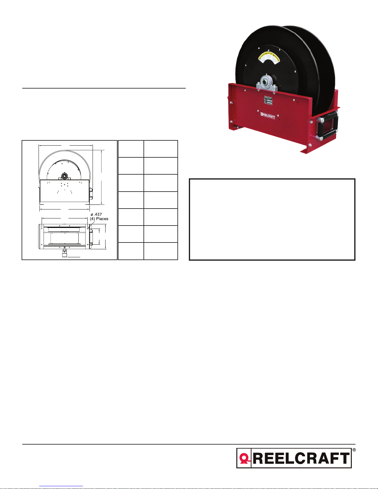
Dimensions
INSTALLATION:
B
A
A 670 mm
B 667 mm
C 565 mm
SAFETY
D 343 mm
F
C
E
D
G
The swivel union is packed separately in the reel carton, use teflon tape to assure a satisfactory seal. A flexible hose
connection must be used between the hose reel inlet and the source of supply to prevent possible misalignment and
binding. Non flexible connections will void the warranty, pressure rating of inlet hose must be equal to or more than
the pressure rating of the reel. Consult factory for proper spring when installing reels above 5 meters.
E 451 mm
F 613 mm
G 98 mm
1. Models designed for fuel are coded with the prefix “F” i.e., “FF9500 OLP.”
Check name plate on the reel before installing.
2. Do not use reel at higher pressures or temperatures than listed on the back
of this bulletin.
3. Remove all spring tension before beginning dissassembly process.
4. Reel spring motor case is permanently sealed. Any attempt to remove the
spring motor may cause serious injury.
LUBRICATION:
REPLACING HOSE:
ADJUSTMENTS:
REPAIRS:
MODIFICATION:
Reelcraft International Inc. • Ph: +44 (0) 1536 406999 • Fax: +44 (0) 1536 406777
Unit 17 - Cronin Courtyard, Weldon South Industrial Estate, Corby - Northamptonshire NN18 8AG
europe@reelcraft.com • www.reelcraft.com/europe
Hose reel spring and bearings are factory lubricated and require no further lubrication.
1. Wind spool flange clockwise-facing swivel-until spring is tight.
2. Back off three turns and latch.
3. Insert hose through roller guide.
4. Connect hose fitting to female outlet ell.
To adjust spring tension, add or remove wraps of hose from the spool, one wrap at a time until desired tension is
obtained.
Extensive repairs should be performed only by an authorized serviceman or factory to avoid damage which may
void your warranty. Remove all spring tension before beginning disassembly process.
Hose latching mechanism can be removed for constant tension applications.
Form# R1152-204 Rev: 2/2016
Page 2
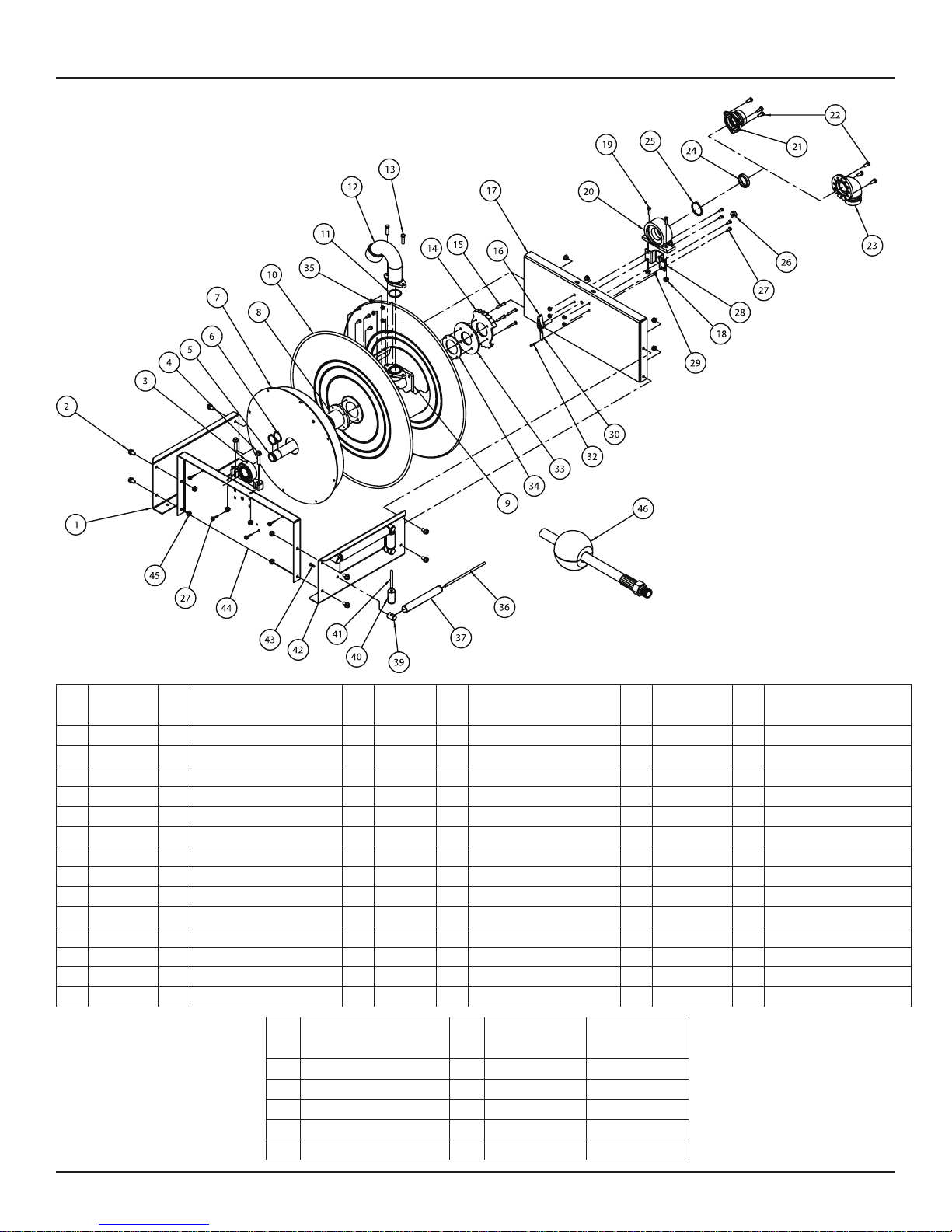
Series FF9000 Spring Driven Hose Reels
Item
Part #
#
1 261112 1 End frame 16 S600454 1 Latch pawl assembly 30 S260067 1 Latch spring
2 S44-2 8 3/8-16 x 5/8” screw 17 261703 1 Side frame 32 S393-2 1 10-32 shoulder screw
3 S600416 1 Pillow block 18 300107 2 5/16-18 hex nut 33 260586 1 Support washer
4 S44-8 4 3/8-16 x 1 3/4” screw 19 S2-55 2 5/16-18 x 1” screw 34 261116 1 Ratchet spacer
5 602313 1 Support shaft 20 602240 1 Bearing housing assembly 35 S281-4 12 1/4-20 hex nut
6 S140-34 2 Snap ring 21 S261692 1 Straight inlet 36 261110 2 Guide roller pin
7 600545-35 1 Spring case assembly 22 S2-53 3 5/16-18 x 3/4” screw 37 262436-10.093 2 Guide roller - long
8 260888 1 Spring arbor 23 261716 1 90° Adapter 39 S270014 4 Guide roller post
9 262270 1 Spindle 9000 24 S600947-1 1 Ring seal 40 262436-2.968 2 Guide roller - short
10 600543-35 1 Sheave assembly 25 S140-45 1 Snap ring
11 S211-224 1 O-ring 26 S280-8 1 1/2-20 hex nut 42 S600542 1 Roller bracket assembly
13 S44-3 2 3/8-16 x 1” screw 27 S2-41 12 1/4-20 x 1/2” screw 43 S2-51 4 5/16-18 x 1/2” screw
14 261115 1 Latch ratchet 28 260934 1 Latch bracket 44 270009 1 Side frame
15 S2-47 4 1/4-20 x 1½” screw 29 S82-15 1 10-32 nyloc nut 45 S281-6 10 3/8-16 hex nut
#
Req
Description
Item
#
12 Gooseneck 1 261793-2 261793-3
46 Bumper stop assembly 1 S600547-1 S600547-2
--
-- Working pressure -- 41 bar 41 bar
-- Max. temperature -- 99 °C 99 °C
Item
Part #
#
Description
Hose ID and length -- 1¼” x 15m 1½” x 15m
#
Req
#
Req
Description
FF9500
OLPBW118
Item
#
41 S270015 2 Guide roller pin
FF9600
OLPBW118
Part #
#
Req
Description
Page 2
www.reelcraft.com
 Loading...