

ReelCraft E9200 OMP, E9400 OMP, E9300 OMP, E9275 OMP, E9450 OMP Operating Instructions Manual
...Page 1
Operating Instructions
Series E9000 Spring Driven Hose Reels
Medium Pressure Model Numbers:
E9200 OMP E9300 OMP E9400 OMP
E9275 OMP E9330 OMP E9450 OMP
E9350 OMP
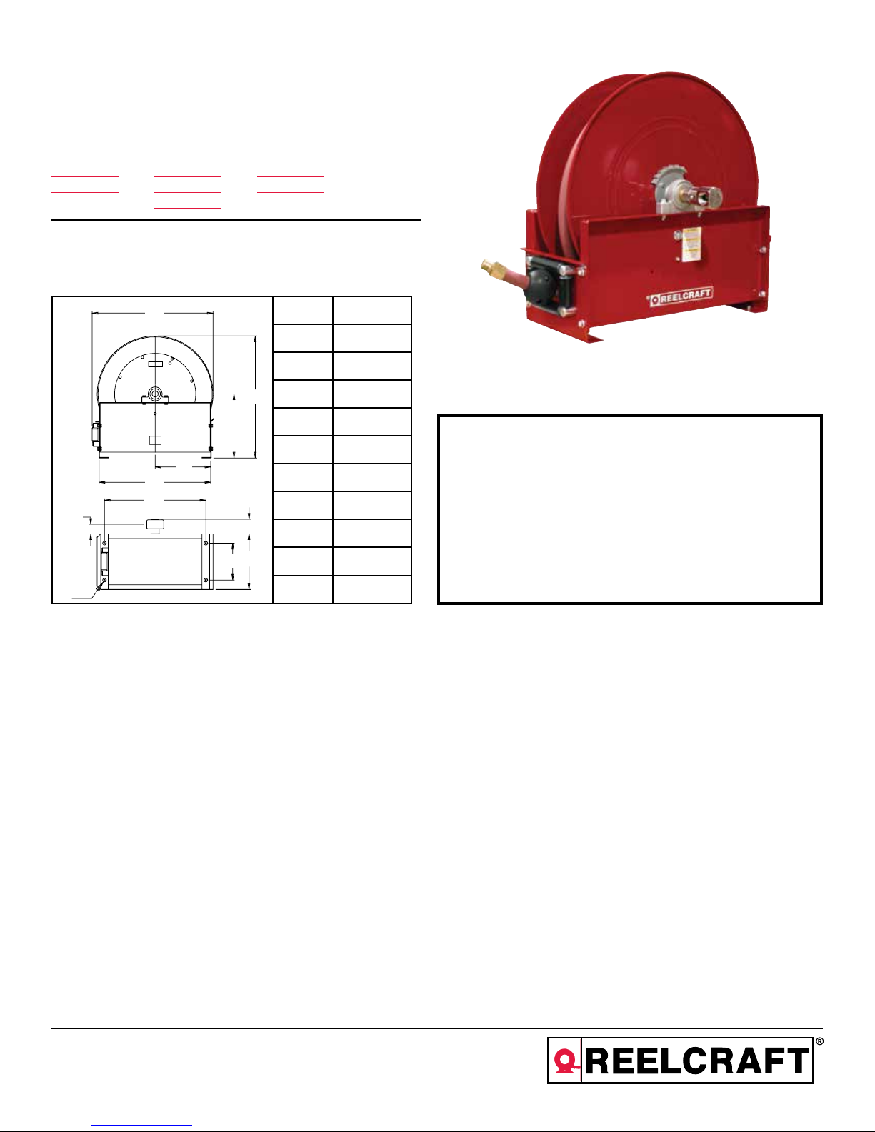
Dimensions
K
L
INSTALLATION:
B
A 26 3/8”
B 26 3/8”
C 13 7/8”
A
C
D 12 1/8”
E 24 1/4”
SAFETY
D
E
F
G
G 4 3/8”
H 12”
J 7 3/4”
F 22 1/4”
H
J
K 3 1/2”
L 7/16”
Four 7/16” diameter mounting holes
The swivel union is packed separately in the reel carton, use teflon tape to assure a satisfactory seal. A flexible hose
connection must be used between the hose reel inlet and the source of supply to prevent possible misalignment and
binding. Non flexible connections will void the warranty, pressure rating of inlet hose must be equal to or more than
the pressure rating of the reel. Consult factory for proper spring when installing reels above 16 ft.
1. Models designed for fuel are coded with the prefix “F” i.e., “FE9400 OMP.”
Check name plate on the reel before installing.
2. Do not use reel at higher pressures or temperatures than listed on the back
of this bulletin.
3. Remove all spring tension before beginning dissassembly process.
4. Reel spring motor case is permanently sealed. Any attempt to remove the
spring motor may cause serious injury.
LUBRICATION:
REPLACING HOSE:
Hose reel spring and bearings are factory lubricated and require no further lubrication.
1. Wind spool flange clockwise-facing swivel-until spring is tight.
2. Back off three turns and latch.
3. Insert hose through roller guide.
4. Connect hose fitting to female outlet ell.
ADJUSTMENTS:
To adjust spring tension, add or remove wraps of hose from the spool, one wrap at a time until desired tension is
obtained.
REPAIRS:
Extensive repairs should be performed only by an authorized serviceman or factory to avoid damage which may
void your warranty. Remove all spring tension before beginning disassembly process.
MODIFICATION:
Reelcraft Industries, Inc. • 2842 E Business Hwy 30, Columbia City, IN 46725
Ph: 800-444-3134 / 260-248-8188 • Fax: 800-444-4587 / 260-248-2605
Customer Service: 855-634-9109 • reelcraft@reelcraft.com • www.reelcraft.com
Hose latching mechanism can be removed for constant tension applications.
Form# 614-193 Rev: 6/2018
Page 2
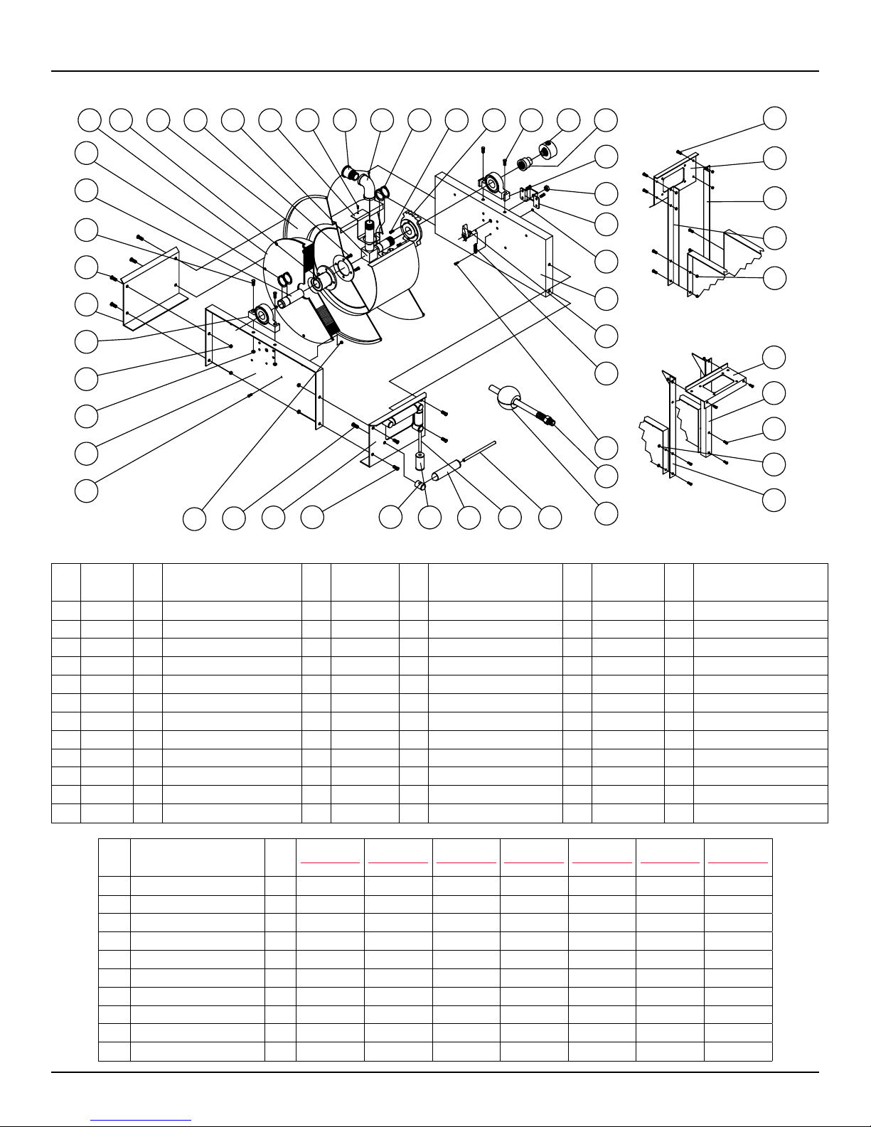
Series E9000 Spring Driven Hose Reels
11
10
9
8
7
6
5
4
3
3
2
1
12
13
37
14 15
36
6
1
38
16
17 9 1
3334
18 7 19
303132
20
4
21
22
23
2
24
25
27
28
29
6
39
40
41
3
42
43
6
3
44
Item
#
Part #
#
Req
Description
Item
#
Part #
#
Req
Description
Item
#
Part #
#
Req
Description
1 S2-41 16 1/4-20 x 1/2” hex screw 15 S32-136 1 #10 x 3/8” self tap screw 32 262436-5.468 2 Guide roller
2 270009 2 Side frame 17 270039 1 90° female NPT ell 33 262436-2.968 2 Guide roller
3 S281-6 12 3/8-16 hex flange nut 18 260889 1 Latch ratchet 34 S270014 4 Guide roller post
4 S600416 2 Pillow block 21 S280-8 1 1/2-20 hex flange nut 36 270011 1 Hose guide roller plate
5 270012 1 End frame support 22 260934 1 Latch bracket 37 S2-51 4 5/16-18 x 1/2” hex screw
6 S44-2 8 3/8-16 x 5/8” mach. screw 23 S82-15 1 10-32 x 3/8” nyloc nut 38 S281-4 8 1/4-20 hex nut
7 S44-8 4 3/8-16 x 1 3/4” screw 24 S600454 1 Latch pawl assembly 39 270045 1 Guide roller plate SW
8 602377 1 Support shaft 25 S260067 1 Latch spring 40 270043 1 SW support bracket
9 S140-34 6 Snap ring 27 S393-2 1 10-32 shoulder screw 41 270042 1 SW support bracket
11 260888 1 Spring arbor 30 S270016 2 Guide roller pin - long 42 270044 1 Guide roller plate TW
13 602364 1 Inlet tube 31 S270015 2 Guide roller pin - short 43 270041 1 TW support bracket
14 270029 1 Hose outlet support 44 270040 1 TW support bracket
Item
#
Description
#
E9200 OMP E9275 OMP E9300 OMP E9330 OMP E9350 OMP E9400 OMP E9450 OMP
Req
10 Spring case assembly 1 600413-1 600413-1 S600413-2 S600413-2 S600413-2 S600413-2 S600413-2
12 Sheave assembly 1 600415 600415 600415 600415 600415 600414 600414
16 Reducing bushing 1 S174-112 S174-112 300055 300055 300055 None None
19 Swivel assembly 1 S602033 S602033 S602026 S602026 S602026 S600682 S600682
20 Reducing coupling 1 S290-5 S290-5 S290-6 S290-6 S290-6 None None
28 Hose assembly 1 None S24-260043 None S26-260043 S27-260043 None 602574-50
29 Bumper stop assembly 1 None 2-HR1005 None 3-HR1005 3-HR1005 None 4-HR1005
-- Hose ID and length -- None 1/2” x 75’ None 3/4” x 30’ 3/4” x 50’ None 1” x 50’
-- Working pressure -- 3250 PSI 3250 PSI 3000 PSI 1250 PSI 1250 PSI 3250 PSI 3250 PSI
-- Max. temperature -- 210 °F 210 °F 210 °F 210 °F 210 °F 210 °F 210 °F
Page 2
www.reelcraft.com
 Loading...