

Page 1
Operating Instructions
Display Stand
Model Numbers:
S602037-1 S602037-2 S602037-3
Tools Required:
Socket wrench
Socket wrench extension
1/2” socket
Tape measure or 12” ruler
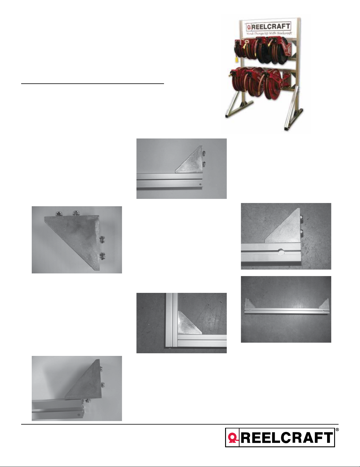
INSTALLATION INSTRUCTIONS
Step 1:
Preassemble twelve of the 45° corner
brackets (#10) with four hex cap screws
(#12) and four Nyloc lock nuts (#14),
each side of the corner bracket (#10)
gets one screw in the slot and one
screw in the hole. See figure 1.
Figure 1
Step 2:
Gather the 20° front legs (#4). Slide one
of the preassembled corner brackets (#10)
into the front leg (#4), by sliding the nuts
into the slot of the leg. Position the bracket
(#10) with the back edge flush with the
end of the leg. Tighten the two screws to
secure the bracket to the leg. (See figures
2 & 3). Repeat process of the second leg
(#4).
Figure 3
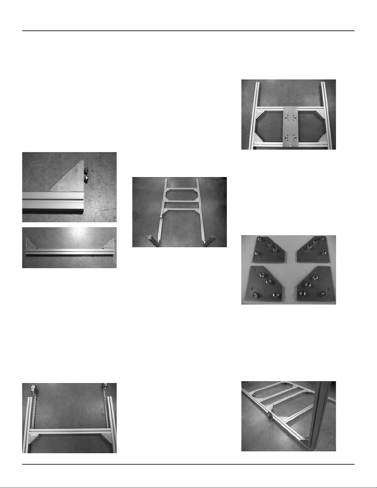
Step 3:
Gather the two uprights (#2) and slide
the nuts from the preassembled corner
bracket (#10) and front leg (#4) into the
slot of the upright (#2). Position the
upright (#2) and leg (#4) so that the
bottom of the upright (#2) is flush with
the bottom of the front leg (#4). Tighten
the two screws to secure the bracket to
the upright (see figure 4). Repeat process
for the second upright (#2).
Figure 4
bar (#8) locating the nuts of the corner
brackets (#10) into the slot of the side
directly above the access holes. Position the corner brackets (#10) so that the
outside edge of each corner bracket (#10)
is flush with the end of the cross bar (#8).
See figures 5 and 6. Repeat process for the
second cross bar with access holes (#8).
Figure 5
Figure 6
Step 4:
Figure 2
Reelcraft Industries, Inc. • 2842 E Business Hwy 30, Columbia City, IN 46725
Ph: 800-444-3134 / 260-248-8188 • Fax: 800-444-4587 / 260-248-2605
Customer Service: 855-634-9109 • reelcraft@reelcraft.com • www.reelcraft.com
Gather the two cross bars with access
holes (#8) and four preassembled
corner brackets (#10). Slide a corner
bracket (#10) into each end of the cross
Form# 1173-705 Rev: 6/2013
Page 2
Reelcraft Display Stand
Step 5:
Gather the two remaining cross bars (#3)
and four preassembled corner brackets
(#10). Slide a corner bracket (#10) into
each end of the cross bar (#3) locating the
nuts of the brackets into one of the slots
of the cross bar (#3). Position the corner
brackets (#10) so that the outside edge of
each bracket is flush with each end of the
cross bar (#3). Tighten the four screws to
secure the two brackets to the cross bar.
(See figures 7 and 8). Repeat process for
the second cross bar (#3).
Figure 7
Figure 8
Step 7:
Place one display stand adapter plate (#1)
on the secured cross bar (#3) by sliding
the bend end of the plate around the cross
bar. From the leg end of the uprights slide
one of the preassembled cross bars with
access holes (#8), with the corner brackets
(#10) pointing away from the legs and
the access holes facing up, into the slots
located inside the two uprights (#2). Position the cross bar (#8) so that the bottom
of the cross bar (#8) is flush with the bottom of the display stand adapter plate (#1).
Tighten the four screws in the brackets
to secure the cross bar with access holes
(#8) into position (see figure 10).
Figure 10
bottom of the display stand adapter plate
(#1). Tighten the four screws in the brackets to secure the cross bar with access
holes (#8) into position (see figure 11).
Figure 11
Step 10:
Gather the four 45° support brackets (#7),
sixteen cap screws (#12) and sixteen
flange nyloc nuts (#9). Preassemble the
support brackets (#7) as shown in figure
12. The two support brackets (#7) on the
left will be for the left side of the display
stand and the two on the right will be for
the right side of the display stand.
Step 6:
Position the two upright (#2) & front leg
(#4) assemblies flat on a hard surface
with the legs pointing up. Slide one of the
preassembled cross bars (#3), with the
brackets pointing toward the legs, into the
slots located inside the two uprights (#2).
Position the cross bar (#3) twelve inches
from the top of the uprights (#2) to the top
of the cross bar (#3). Be sure to measure
each side of the cross bar. Tighten the four
screws in the brackets to secure the cross
bar (#3) into position (see figure 9).
Figure 9
Step 8:
From the leg end of the uprights, slide the
remaining preassembled cross bar (#3),
with the corner brackets (#10) pointing toward the legs, into the slots located inside
the two uprights (#2). Position the cross
bar (#3) six inches from the bottom of the
secured cross bar with access holes (#8)
to the top of the cross bar (#3), be sure to
measure each side of the cross bar (#3).
Tighten the four screws in the brackets to
secure the cross bar (#3) into position.
Step 9:
Place one display stand adapter plate (#1)
on the second secured cross bar (#3) by
sliding the bent end of the plate around
the cross bar (#3). From the leg end of the
uprights (#2) slide the remaining preassembled cross bar with access holes (#8),
with the corner brackets (#10) pointing
away from the front legs (#4), into the
slots located inside the two uprights (#2).
Position the cross bar (#8) so that the bottom of the cross bar (#8) is flush with the
Figure 12
Step 11:
Slide the top left side preassembled support brackets (#7) into the bottom end of
the left upright until it is near the middle of
the lower set of cross bars. The cap screw
(#12) heads will slide into the slots so the
the flange nyloc nuts (#9) will be exposed
(see figure 15).
Figure 13
Page 2
www.reelcraft.com
Page 3

Reelcraft Display Stand
Step 12:
Slide the bottom left side preassembled
support bracket (#7) into one of the 45°
supports (#6) as shown in figure 14. The
cap screw (#12) heads will slide into the
slots so that the flange nyloc nuts (#9) will
be exposed.
Figure 14
Step 13:
While holding the 45° support (#6) and
45° support bracket (#7) slide the cap
screws (#12) sticking out from the 45°
support bracket (#7) into the slot of the left
front leg (#4) while sliding the 45° support (#6) onto the cap screws (#12) of the
second support bracket (#7) that is slid
into the upright (#2). Once the 45° support
(#6) is in place align the end of the support near flush with the end of the leg and
tighten the eight cap screws (#12) to secure the 45° support (#6) (see figure 15).
Figure 15
Step 14:
Slide the top right side preassembled
support bracket (#7) into the bottom end
of the right upright (#2) until it is near the
middle of the lower set of cross bars. The
cap screw (#12) heads will slide into the
slots so that the flange nyloc nuts (#9) will
be exposed (see figure 16).
Figure 16
Step 15:
Slide the bottom right side preassembled
support bracket (#7) into the remaining
45° support (#6) as shown in figure 17.
The cap screw (#12) heads will slide into
the slots so that the flange nyloc nuts (#9)
will be exposed.
Figure 17
Step 16:
While holding the 45° support (#6) and
45° support bracket (#7) slide the cap
screws (#12) sticking out from the 45°
support bracket (#7) into the slot of the
right front leg (#4) while sliding the 45°
support onto the cap screws (#12) of the
second support bracket (#7) that is slid
into the upright (#2). Once the 45° support
(#6) is in place align the end of the support near flush with the end of the leg and
tighten the eight cap screws (#12) to secure the 45° support (#6) (see figure 18).
Figure 18
Step 17:
Gather the two back legs (#5) and the
remaining two preassembled 45° corner
brackets (#10). Slide one of the preassembled corner brackets into the back
leg (#5) by sliding the nuts into the slot
of the leg. Position the corner bracket
(#10) with the back edge flush with the
end of the leg. Tighten the two screws
to secure the bracket to the leg. Repeat
process for the second back leg (#5)
(see figure 19).
Figure 19
Step 18:
Turn the upright assembly over onto one
side. Slide one of the preassembled back
legs (#5) into the bottom of the upright
(#2) until the bottom of the back leg (#5)
is flush with the bottom of the upright
(#2). Tighten the two screws to secure the
leg to the upright. Slide the second preassembled back leg (#5) into the bottom of
the opposite upright (#2) until the bottom
of the back leg (#5) is flush with the bottom of the upright (#2). Tighten the two
screws to secure the back leg (#5) to the
upright (#2) (see figure 20).
Figure 20
www.reelcraft.com
Page 3
Page 4

Reelcraft Display Stand
Step 19:
Gather four of the end caps (#11) and attach them to the ends of both of the front
legs (#4) and the back legs (#5) (see
figure 21).
Figure 21
Step 20:
Stand the display stand assembly upright.
Gather six of the cap screws (#12) and
slide three in each of the two cross bars
with access holes (#8) by sticking the
head of the cap screw (#12) into the access hole then slide into position (see
figure 22).
figure 27).
Figure 24
Step 22:
Gather six of the lock nuts (#13) and hand
tighten them to the cap screws (#12) to
hold the display stand adapter plate (#1) in
place (see figure 25).
Figure 27
Figure 25
Figure 22
Step 21:
Place the six display stand adapter plates
(#1) into position by sliding the bent end
over the top cross bars (#3) and aligning
the cap screw (#12) into the slot located
in the bottom of the display stand adapter
plate (#1) (see figures 23 and 24).
Figure 23
Step 23:
Gather the four strips of graphic gasket
and slide two down into the top of the
upright (#2) in the slot facing the cross
bars, refer to Figure 26 for orientation.
Repeat for the other upright.
Figure 26
Add reels to display stand
To assemble a reel to the display stand
align the mounting holes of the reel with
the appropriate mounting hole pattern on
the display stand adapter plate (#1). Attach the reel using four cap screws (#12)
and four lock nuts (#13). The display
stand adapter plates can be adjusted to set
proper spacing on the display stand (see
Page 4
www.reelcraft.com
Page 5

Reelcraft Display Stand
www.reelcraft.com
Page 5
Page 6

Reelcraft Display Stand
NO. S602037-1 S602037-2 S602037-3 PART# DESCRIPTION
1 8 6 4 261918-37 Plate, Display Stand Adapter
2 2 2 2 261919 Upright
3 2 0 0 261920-1 Cross Bar
3 0 2 0 261920-2 Cross Bar
3 0 0 2 261920-3 Cross Bar
4 2 2 2 261921 Leg, Front
5 2 2 2 S261922 Leg, Back
6 2 2 2 S261923 Suport, 45°
7 4 4 4 261924-37 Support Bracket, 45°
8 1 0 0 261948-1 Graphics, Display Stand
8 0 1 0 261948-2 Graphics, Display Stand
8 0 0 1 261948-3 Graphics, Display Stand
9 4 4 4 261950 Gasket, Graphic Stabilizer
10 2 0 0 261951-1 Cross Bar (with end holes)
10 0 2 0 261951-2 Cross Bar (with end holes)
10 0 0 2 261951-3 Cross Bar (with end holes)
11 16 16 16 261650 Lock Nut, Hex Flange with Nylon Insert
12 12 12 12 261739-R 45° Bracket
13 6 6 6 261740 Cap, End
14 40 30 20 300107 Lock, Nut
15 104 94 84 S2-53 Screw, Hex Cap
16 48 48 48 S85-7 Nut, Nyloc
Parts List
Quantity / Model
Page 6
www.reelcraft.com
 Loading...