

Page 1
Operating Instructions
Series D9000 Spring Driven Hose Reels
Low Pressure Model Numbers:
D9200 OLP D9305 OLP D9375 OLP D9450 OLP
D9275 OLP D9330 OLP D9399 OLP D9405 OLPBW
D9299 OLP D9340 OLP D9400 OLP D9465 OLPBW
D9300 OLP D9350 OLP D9430 OLP
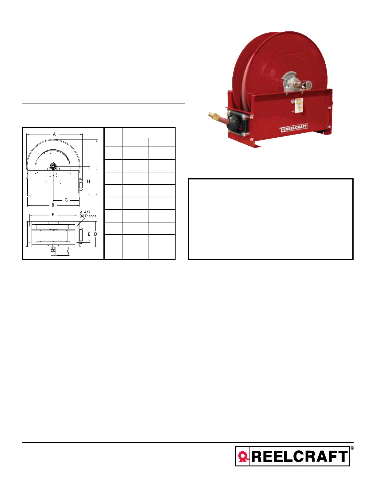
Dimensions
Size Index #
1 2
A 26 1/4” 26 1/4”
B 24 1/8” 24 1/8”
C 4 3/4” 4 1/2”
D 12” 13 3/8”
E 7 3/4” 7 3/4”
1. Models designed for fuel are coded with the prefix “F” i.e., “FD9400 OLP.”
Check name plate on the reel before installing.
SAFETY
See page 3 charts for size index number.
INSTALLATION:
LUBRICATION:
REPLACING HOSE:
ADJUSTMENTS:
F 22 1/4” 22 1/4”
G 12 1/4” 12 1/4”
H 13 7/8” 13 7/8”
J 26 3/8” 26 3/8”
The swivel union is packed separately in the reel carton, use teflon tape to assure a satisfactory seal. A flexible hose
connection must be used between the hose reel inlet and the source of supply to prevent possible misalignment and
binding. Non flexible connections will void the warranty, pressure rating of inlet hose must be equal to or more than
the pressure rating of the reel. Consult factory for proper spring when installing reels above 16 ft.
Hose reel spring and bearings are factory lubricated and require no further lubrication.
1. Wind spool flange clockwise-facing swivel-until spring is tight.
2. Back off three turns and latch.
3. Insert hose through roller guide.
4. Connect hose fitting to female outlet ell.
To adjust spring tension, add or remove wraps of hose from the spool, one wrap at a time until desired tension is
obtained.
2. Do not use reel at higher pressures or temperatures than listed on the back
of this bulletin.
3. Remove all spring tension before beginning dissassembly process.
4. Reel spring motor case is permanently sealed. Any attempt to remove the
spring motor may cause serious injury.
REPAIRS:
MODIFICATION:
Reelcraft Industries, Inc. • 2842 E Business Hwy 30, Columbia City, IN 46725
Ph: 800-444-3134 / 260-248-8188 • Fax: 800-444-4587 / 260-248-2605
Customer Service: 855-634-9109 • reelcraft@reelcraft.com • www.reelcraft.com
Extensive repairs should be performed only by an authorized serviceman or factory to avoid damage which may
void your warranty. Remove all spring tension before beginning disassembly process.
Hose latching mechanism can be removed for constant tension applications.
Form# 835-696 Rev: 4/2014
Page 2
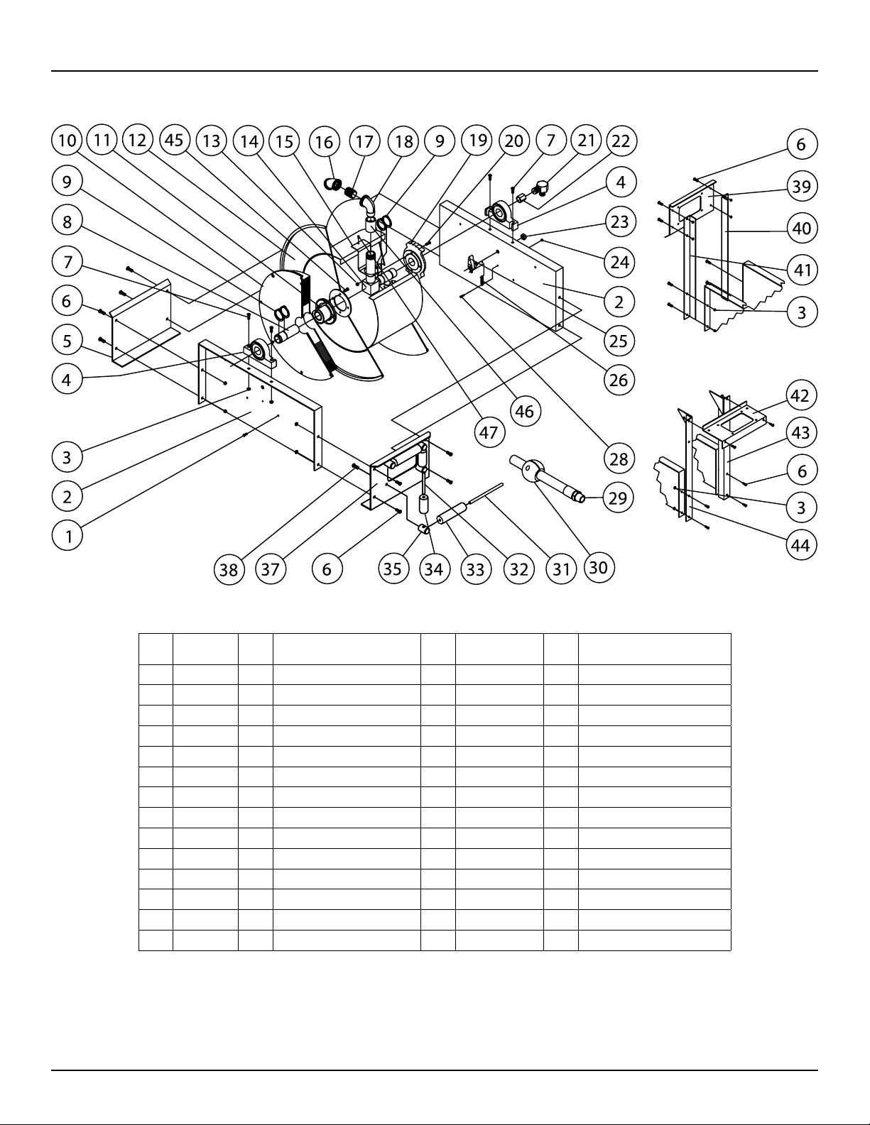
Series D9000 Spring Driven Hose Reels
Item
Part #
#
1 S2-41 4 1/4-20 x 1/2” hex screw 20 S2-42 4 1/4-20 x 5/8” hex screw
2 270009 2 Side frame 23 S280-8 1 1/2-20 hex flange nut
3 S281-6 12 3/8-16 hex flange nut 24 S82-15 1 10-32 x 3/8” nyloc nut
4 270058 2 Pillow block 25 S600018 1 Latch pawl assembly
6 S44-2 8 3/8-16 x 5/8” mach. screw 26 S260067 1 Latch spring
7 S44-8 4 3/8-16 x 1 3/4” screw 28 S393-2 1 10-32 shoulder screw
8 270060 1 Support shaft 31 S270016 2 Guide roller pin - long
9 S140-31 6 Snap ring 32 S270015 2 Guide roller pin - short
10 270105 1 Spring & case assembly 33 262436-5.468 2 Guide roller
11 270002 1 Spring arbor 34 262436-2.968 2 Guide roller
13 S281-4 8 1/4-20 hex flange nut 35 S270014 4 Guide roller post
14 S270054 1 1” Inlet tube 38 S2-51 4 5/16-18 x 1/2” hex screw
15 270029 1 Hose outlet support 45 S328-29 4 Self tapping screw
19 S270001 1 Latch ratchet hub 47 S32-136 1 #10 x 3/8” self tap screw
#
Req
Description
Item
#
Part #
#
Req
Description
Page 2
www.reelcraft.com
Page 3

Series D9000 Spring Driven Hose Reels
Item
#
5 End frame support 1 270012 270012 270012 270012 270012 270012 270012 270012
12 Sheave assembly 1 270107 270107 270107 270107 270107 270107 270107 270107
16 45° Elbow 1 None None None None None None None None
17 Bushing 1 300080 300080 300080 270025 270025 270025 270025 270025
18 90° Elbow 1 270028 270028 270028 270028 270028 270028 270028 270028
21 Swivel assembly 1 600888 600888 600888 S602026 S602026 S602026 S602026 S602026
22 Coupling reducer 1 S289-5 S289-5 S289-5 S289-6 S289-6 S289-6 S289-6 S289-6
29 Hose assembly 1 None 601020-75 601020-100 None 601026-30 601026-40 601026-50 601026-75
30 Hose bumper 1 None A2-HR1005 A2-HR1005 None A3-HR1005 A3-HR1005 A3-HR1005 A3-HR1005
37 Hose guide roller plate 1 270011 270011 270011 270011 270011 270011 270011 270011
39 Guide roller plate SW 1 270045 270045 270045 270045 270045 270045 270045 270045
40 SW support bracket 1 270043 270043 270043 270043 270043 270043 270043 270043
41 SW support bracket 1 270042 270042 270042 270042 270042 270042 270042 270042
42 Guide roller plate TW 1 270044 270044 270044 270044 270044 270044 270044 270044
43 TW support bracket 1 270041 270041 270041 270041 270041 270041 270041 270041
44 TW support bracket 1 270040 270040 270040 270040 270040 270040 270040 270040
46 Coupling 1 None None None None None None None None
-- Hose ID and length -- None 1/2” x 75’ 1/2” x 100’ None 3/4” x 30’ 3/4” x 40’ 3/4” x 50’ 3/4” x 75’
-- Working pressure -- 500 PSI 300 PSI 300 PSI 500 PSI 250 PSI 250 PSI 250 PSI 250 PSI
-- Max. temperature -- 210 °F 150 °F 150 °F 210 °F 150 °F 150 °F 150 °F 150 °F
Description
Size Index Number 1 1 1 1 1 1 1 1
#
D9200 OLP D9275 OLP D9299 OLP D9300 OLP D9330 OLP D9340 OLP D9350 OLP D9375 OLP
Req
Item
#
5 End frame support 1 262104 262104 270012 270012 270012 262104 262104
12 Sheave assembly 1 601081 601081 270106 270106 270106 602561 902561
16 45° Elbow 1 None None 262452 262452 262452 262452 262452
17 Bushing 1 270025 270025 None None None None None
18 90° Elbow 1 270028 270028 262451 262451 262451 270028 270028
21 Swivel assembly 1 S602026 S602026 S600682-1 S600682-1 S600682-1 S600682 S600682
22 Coupling reducer 1 S289-5 S289-5 None None None None None
29 Hose assembly 1 None 601026-100 None 601027-30 601027-50 None 601027-65
30 Hose bumper 1 None A3-HR1005 None A4-HR1005 A4-HR1005 None A4-HR1005
37 Hose guide roller plate 1 262103 262103 270011 270011 270011 262103 262103
39 Guide roller plate SW 1 None None 270045 270045 270045 None None
40 SW support bracket 1 None None 270043 270043 270043 None None
41 SW support bracket 1 None None 270042 270042 270042 None None
42 Guide roller plate TW 1 262679 262679 270044 270044 270044 None None
43 TW support bracket 1 270041 270041 270041 270041 270041 None None
44 TW support bracket 1 270040 270040 270040 270040 270040 None None
46 Coupling 1 None None 262453 262453 262453 None None
-- Hose ID and length -- None 3/4” x 100’ None 1” x 30’ 1” x 50’ None 1” x 65’
-- Working pressure -- 500 PSI 250 PSI 500 PSI 250 PSI 250 PSI 250 PSI 250 PSI
-- Max. temperature -- 210 °F 150 °F 210 °F 150 °F 150 °F 150 °F 150 °F
Description
Size Index Number 2 2 1 1 1 2 2
#
D9305 OLP D9399 OLP D9400 OLP D9430 OLP D9450 OLP
Req
D9405
OLPBW
D9465
OLPBW
www.reelcraft.com
Page 3
Page 4

Instrucciones de Operacion
Series D9000 Carreteles para Mangueras
Baja presion modelos y numeros:
D9200 OLP D9305 OLP D9375 OLP D9450 OLP
D9275 OLP D9330 OLP D9399 OLP D9405 OLPBW
D9299 OLP D9340 OLP D9400 OLP D9465 OLPBW
D9300 OLP D9350 OLP D9430 OLP
Dimensiones
Índice del tamaño #
1 2
A 26 1/4” 26 1/4”
B 24 1/8” 24 1/8”
C 4 3/4” 4 1/2”
D 12” 13 3/8”
E 7 3/4” 7 3/4”
F 22 1/4” 22 1/4”
G 12 1/4” 12 1/4”
H 13 7/8” 13 7/8”
J 26 3/8” 26 3/8”
Vea las cartas de la página 6 para el número de índice del tamaño.
1. Los modelos diseñados para gasolina estan codificados con la prefixse “F”
i.e., “FD9400 OLP” chequee el nombre en la place del carretel antes de la
instalacion.
2. No use carreteles a presiones o temperaturas altas que no se mencionan en
este boletin.
3. Remueva la tension de resorte antes de empezar el proceso de desmontaje.
4. El resorte del motor de la caja del carretel esta permanentemente cerrado.
Cualquier atentado para remover el resorte del motor podria causar serios
daños.
SEGURIDAD
INSTALACION:
LUBRICACION:
REMPLAZO DE
LA MANGUERA:
ADJUSTAMIENTO:
REPARACION:
MODIFICACION:
Page 4
Reelcraft Industries, Inc. • 2842 E Business Hwy 30, Columbia City, IN 46725
Ph: 800-444-3134 / 260-248-8188 • Fax: 800-444-4587 / 260-248-2605
Customer Service: 855-634-9109 • reelcraft@reelcraft.com • www.reelcraft.com
La articulacion giratoria esta empacada separadamente en la caja del carretel, use una cinta de teflon para asegurar
un sello satisfactorio una manguera de conexcion flexible debe ser usada entre la entrada de la manguera del carretel y la fuente de abastecimiento para prevenir un posible desalineamiento y enlazamiento. Una que no es flexibel
podria eliminar la garantia, la capacidad de presion de la salida de la manguera sea igual o mas que la capacidad
de la presion en el carretel. Consulte a la fabrica por el resorte apropiado para la instalacion de carretes de más de
16 pies.
El resorte del carretel de la manguera esta empacado con grasa y no requiere futura lubricacion.
1. Dele vueltas a la palanca giratoria hacia la derecha hasta que el resorte este apretado.
2. Devuelva 3 giros y asegure.
3. Inserte la manguera atravez de la guia del rodillo.
4. Conecte y encaje la manguera a la salida hembra de el codo de tuberia.
Para ajustar la tension del resorte en el carretel, agrege o quite vueltas hasta que la tension deseada es
obtenidad.
Extensivas reparaciones deberan ser realizadas por una persona de servicio autorizada o por la fabrica para evitar
daños que eliminen su garantia. Remueva todos los resortes de tension antes del proceso de desmontaje.
El mecanismo de seguro puede ser removido para una aplicacion constante de tension.
Form# 835-696 Rev: 4/2014
Page 5

Series D9000 Carreteles para Mangueras
Arti
Part No.
culo
1 S2-41 4 1/4-20 x 1/2” tornillo hexagonal 20 S2-42 4 1/4-20 x 5/8” tornillo hexagonal
2 270009 2 Lado del marco 23 S280-8 1 1/2-20 tuerca hexagonal
3 S281-6 12 3/8-16 tuerca hexagonal 24 S82-15 1 10-32 x 3/8” tuerca
4 270058 2 Almuada del bloque 25 600018 1 Seguro de encaje ensamblado
6 S44-2 8 3/8-16 x 5/8” tornillo 26 260067 1 Seguro de resorte
7 S44-8 4 3/8-16 x 1 3/4” tornillo 28 S393-2 1 10-32 tornillo de hombro
8 270060 1 Soporte de la columna 31 270016 2 Rodillo guia del eje largo
9 S140-31 6 Aro de resorte 32 270015 2 Rodillo guia del eje corto
10 270105 1 Caja de resort ensamblado 33 262436-5.468 2 Rodillo guia
11 270002 1 Resorte de tambor 34 262436-2.968 2 Rodillo guia
13 S281-4 8 1/4-20 tuerca hexagonal 35 270014 4 Rodillo guia de la columna
14 270054 1 1” tubo de entrada 38 S2-51 4 5/16-18 x 1/2” tornillo hexagonal
15 270029 1 Soporte de salida de la manguera 45 S328-29 4 Tornillo penetrante
19 270001 1 Seguro retenedor del eje 47 S32-136 1 #10 x 3/8” tornillo que golpea ligeramente
www.reelcraft.com
No.
Req
Descripcion
Arti
culo
Part No.
No.
Req
Descripcion
Page 5
Page 6

Series D9000 Carreteles para Mangueras
Arti
culo
5 Final del marco de soporte 1 270012 270012 270012 270012 270012 270012 270012 270012
12 Rueda exentrica ensamblada 1 270107 270107 270107 270107 270107 270107 270107 270107
16 45° codo 1 Ninguno Ninguno Ninguno Ninguno Ninguno Ninguno Ninguno Ninguno
17 Casquillo 1 300080 300080 300080 270025 270025 270025 270025 270025
18 90° codo 1 270028 270028 270028 270028 270028 270028 270028 270028
21 Eje giratorio ensamblado 1 600888 600888 600888 S602026 S602026 S602026 S602026 S602026
22 Acoplamiento reductor 1 S289-5 S289-5 S289-5 S289-6 S289-6 S289-6 S289-6 S289-6
29 Manguera ensamblada 1 Ninguno 601020-75 601020-100 Ninguno 601026-30 601026-40 601026-50 601026-75
Parachoque de la manguera
30
ensamblada
37 Rodillo guia del plato 1 270011 270011 270011 270011 270011 270011 270011 270011
39 Guia del rodillo del plato SW 1 270045 270045 270045 270045 270045 270045 270045 270045
40 SW soporte de la abradadera 1 270043 270043 270043 270043 270043 270043 270043 270043
41 SW soporte de la abradadera 1 270042 270042 270042 270042 270042 270042 270042 270042
42 Guia del rodillo del plato TW 1 270044 270044 270044 270044 270044 270044 270044 270044
43 TW soporte de la abradadera 1 270041 270041 270041 270041 270041 270041 270041 270041
44 TW soporte de la abradadera 1 270040 270040 270040 270040 270040 270040 270040 270040
46 Acoplador 1 Ninguno Ninguno Ninguno Ninguno Ninguno Ninguno Ninguno Ninguno
Identificacion de la manguera y
--
largo
-- Maxima presion de operacion -- 500 PSI 300 PSI 300 PSI 500 PSI 250 PSI 250 PSI 250 PSI 250 PSI
-- Maxima temperatura de operacion -- 210 °F 150 °F 150 °F 210 °F 150 °F 150 °F 150 °F 150 °F
Índice del tamaño # 1 1 1 1 1 1 1 1
Descripcion
No.
D9200 OLP D9275 OLP D9299 OLP D9300 OLP D9330 OLP D9340 OLP D9350 OLP D9375 OLP
Req
1 Ninguno A2-HR1005 A2-HR1005 Ninguno A3-HR1005 A3-HR1005 A3-HR1005 A3-HR1005
-- Ninguno 1/2” x 75’ 1/2” x 100’ Ninguno 3/4” x 30’ 3/4” x 40’ 3/4” x 50’ 3/4” x 75’
Arti
culo
5 Final del marco de soporte 1 262104 262104 270012 270012 270012 262104 262104
12 Rueda exentrica ensamblada 1 601081 601081 270106 270106 270106 602561 902561
16 45° codo 1 Ninguno Ninguno 262452 262452 262452 262452 262452
17 Casquillo 1 270025 270025 Ninguno Ninguno Ninguno Ninguno Ninguno
18 90° codo 1 270028 270028 262451 262451 262451 270028 270028
21 Eje giratorio ensamblado 1 S602026 S602026 S600682-1 S600682-1 S600682-1 S600682 S600682
22 Acoplamiento reductor 1 S289-5 S289-5 Ninguno Ninguno Ninguno Ninguno Ninguno
29 Manguera ensamblada 1 Ninguno 601026-100 Ninguno 601027-30 601027-50 Ninguno 601027-65
Parachoque de la manguera
30
ensamblada
37 Rodillo guia del plato 1 262103 262103 270011 270011 270011 262103 262103
39 Guia del rodillo del plato SW 1 Ninguno Ninguno 270045 270045 270045 Ninguno Ninguno
40 SW soporte de la abradadera 1 Ninguno Ninguno 270043 270043 270043 Ninguno Ninguno
41 SW soporte de la abradadera 1 Ninguno Ninguno 270042 270042 270042 Ninguno Ninguno
42 Guia del rodillo del plato TW 1 262679 262679 270044 270044 270044 Ninguno Ninguno
43 TW soporte de la abradadera 1 270041 270041 270041 270041 270041 Ninguno Ninguno
44 TW soporte de la abradadera 1 270040 270040 270040 270040 270040 Ninguno Ninguno
46 Acoplador 1 Ninguno Ninguno 262453 262453 262453 Ninguno Ninguno
Identificacion de la manguera y
-largo
-- Maxima presion de operacion -- 500 PSI 250 PSI 500 PSI 250 PSI 250 PSI 250 PSI 250 PSI
-- Maxima temperatura de operacion -- 210 °F 150 °F 210 °F 150 °F 150 °F 150 °F 150 °F
Índice del tamaño # 2 2 1 1 1 2 2
Descripcion
No.
D9305 OLP D9399 OLP D9400 OLP D9430 OLP D9450 OLP
Req
1 Ninguno A3-HR1005 Ninguno A4-HR1005 A4-HR1005 Ninguno A4-HR1005
-- Ninguno 3/4” x 100’ Ninguno 1” x 30’ 1” x 50’ Ninguno 1” x 65’
D9405
OLPBW
D9465
OLPBW
Page 6
www.reelcraft.com
Page 7

Instructions D’Opération
Série D9000 Enrouleur de Tuyau Manuels
Basse pression numéros de modèle:
D9200 OLP D9305 OLP D9375 OLP D9450 OLP
D9275 OLP D9330 OLP D9399 OLP D9405 OLPBW
D9299 OLP D9340 OLP D9400 OLP D9465 OLPBW
D9300 OLP D9350 OLP D9430 OLP
Dimensions
Index de taille #
1 2
A 26 1/4” 26 1/4”
B 24 1/8” 24 1/8”
C 4 3/4” 4 1/2”
D 12” 13 3/8”
E 7 3/4” 7 3/4”
F 22 1/4” 22 1/4”
G 12 1/4” 12 1/4”
H 13 7/8” 13 7/8”
J 26 3/8” 26 3/8”
Voir les diagrammes de la page 9 pour l’index de taille.
INSTALLATION:
LUBRIFICATION:
REMPLACEMENT
DE TUYAU:
Le joint de pivot est emballé séparément dans le carton de l’enrouleur. Utilisez du ruban à téflon pour assurer un
cachet satisfaisant. Un raccord d’enrouleur flexible doit être utilisé entre l’entrée d’enrouleur de tuyau et la source
d’alimentation pour éviter le défaut d’alignement et le coincement. Des raccords inflexibles vont annuler la garantie.
La capacité de pression de tuyau d’entrée doit être la meme ou plus haute que celle de l’enrouleur. Consultez l’usine
pour le ressort correct our installer les enrouleur plus hauts que 16 pieds.
Le ressort de l’enrouleur et les paliers sont lubrifiés à vie en usine.
1. Enroulez le tambour bridé dans le sens des aiguilles d’une montre (face au pivot) jusqu’ au ressort est bien serré.
2. Faites marche arrière 3 tours, et puis fermez au loquet le mécanisme.
3. Insérez le tuyau à travers le guide et le trou de la pièce d’espacement bridée.
4. Connectez le raccord de tuyau au joint de pivot, et fixez le tuyau avec des crampons.
LA SÉCURITÉ
1. Les modèles désignés pour combustible sont codées avec le préfixe “F”
i.e., FD9400 OLP. Vérifiez le numéro sur la plaque d’enrouleur avant
d’installer.
2. N’utilisez pas les enrouleurs à pression plus haute ou aux températures
plus hauts que ce qui sont notés sur le dos de ce bulletin.
3. Enlevez toute tension du ressort avant de désassembler.
4. Le boîtier de moteur de ressort d’enrouleur est fermé de facon permanente.
Des tentatives d’enlever le moteur des ressort peuvent causer des blessures
sérieuses.
RÉGLAGES:
RÉPARATIONS:
MODIFICATION:
Page 7
Reelcraft Industries, Inc. • 2842 E Business Hwy 30, Columbia City, IN 46725
Ph: 800-444-3134 / 260-248-8188 • Fax: 800-444-4587 / 260-248-2605
Customer Service: 855-634-9109 • reelcraft@reelcraft.com • www.reelcraft.com
Pour régler la tension du ressort, ajoutez ou enlevez des tours de câble, un tour à la fois, jusqu’à l’obtention de la
tension désirée.
Des réparations étendues doivent être fait uniquement par un homme de service authorisé ou par l’usine pour éviter
le dommage qui peut annuler votre garantie. Enlevez toute tension de resort avant de désassembler.
Le mécanisme verrouillable de tuyau peut être enlevé pour des applications de tension continuelle.
Form# 835-696 Rev: 4/2014
Page 8

Série D9000 Enrouleur de Tuyau Manuels
Article #N°de
pièce
1 S2-41 4 1/4-20 x 1/2” vis hexagonale 20 S2-42 4 1/4-20 x 5/8” vis hexagonale
2 270009 2 Cadre latéral 23 S280-8 1 1/2-20 écrouà embase hexagonal
3 S281-6 12 3/8-16 écrou a embàse 24 S82-15 1 10-32 x 3/8” écrou Nyloc
4 270058 2 Hexagonal support 25 600018 1 Assemblage de cliquet
6 S44-2 8 3/8-16 x 5/8” vis à métaux 26 260067 1 Ressort de loquet
7 S44-8 4 3/8-16 x 1 3/4” vis 28 S393-2 1 10-32 vis à épaulement
8 270060 1 Arbre de support 31 270016 2 Bronche de guide à molette-longue
9 S140-31 6 Dispositif de retenue 32 270015 2 Bronche de guide à molette-courte
10 270105 1 Assemblage de ressort et boîtier 33 262436-5.468 2 Tube de guide à molette
11 270002 1 Mandrin de ressort 34 262436-2.968 2 Tube de guide à molette
13 S281-4 8 1/4-20 écrouàembase 35 270014 4 Douille de guide à molette
14 270054 1 Hexagonal tuyau d’entrée 1 pouce 38 S2-51 4 5/16-18 x 1/2” vis hexagonale
15 270029 1 Support de tuyau de sortie 45 S328-29 4 Vis à tôle
19 270001 1 Moyeu en dent de scie 47 S32-136 1 #10 x 3/8” vis de tapement
N°
requis
Déscription
Article #N°de
pièce
N°
requis
Déscription
Page 8
www.reelcraft.com
Page 9

Série D9000 Enrouleur de Tuyau Manuels
Article
#
5 Support de cadre d’extrémité 1 270012 270012 270012 270012 270012 270012 270012 270012
12 Assemblage de poulie 1 270107 270107 270107 270107 270107 270107 270107 270107
16 45° coude 1 Aucun Aucun Aucun Aucun Aucun Aucun Aucun Aucun
17 Douille 1 300080 300080 300080 270025 270025 270025 270025 270025
18 90° coude 1 270028 270028 270028 270028 270028 270028 270028 270028
21 Assemblage de pivot 1 600888 600888 600888 S602026 S602026 S602026 S602026 S602026
22 Raccord de réduction 1 S289-5 S289-5 S289-5 S289-6 S289-6 S289-6 S289-6 S289-6
29 Assemblage de tuyau 1 Aucun 601020-75 601020-100 Aucun 601026-30 601026-40 601026-50 601026-75
30 Assemblage d’arrêt de tuyau 1 Aucun A2-HR1005 A2-HR1005 Aucun A3-HR1005 A3-HR1005 A3-HR1005 A3-HR1005
37 Plaque de guide à molette 1 270011 270011 270011 270011 270011 270011 270011 270011
Plaque de guide à molette
39
pour enrouler de côté
40 Support pour enrouler de côté 1 270043 270043 270043 270043 270043 270043 270043 270043
41 Support pour enrouler de côté 1 270042 270042 270042 270042 270042 270042 270042 270042
Plaque de guide à molette
42
pour enrouler de haut
43 Support pour enrouler de haut 1 270041 270041 270041 270041 270041 270041 270041 270041
44 Support pour enrouler de haut 1 270040 270040 270040 270040 270040 270040 270040 270040
46 Accouplement 1 Aucun Aucun Aucun Aucun Aucun Aucun Aucun Aucun
Diamétre intérieur et longuer
-du tuyau
-- Pression de régime -- 500 PSI 300 PSI 300 PSI 500 PSI 250 PSI 250 PSI 250 PSI 250 PSI
-- Température maximum -- 210 °F 150 °F 150 °F 210 °F 150 °F 150 °F 150 °F 150 °F
Index de taille # 1 1 1 1 1 1 1 1
Déscription
N°
D9200 OLP D9275 OLP D9299 OLP D9300 OLP D9330 OLP D9340 OLP D9350 OLP D9375 OLP
requis
1 270045 270045 270045 270045 270045 270045 270045 270045
1 270044 270044 270044 270044 270044 270044 270044 270044
-- Aucun 1/2” x 75’ 1/2” x 100’ Aucun 3/4” x 30’ 3/4” x 40’ 3/4” x 50’ 3/4” x 75’
Article
#
5 Support de cadre d’extrémité 1 262104 262104 270012 270012 270012 262104 262104
12 Assemblage de poulie 1 601081 601081 270106 270106 270106 602561 902561
16 45° coude 1 Aucun Aucun 262452 262452 262452 262452 262452
17 Douille 1 270025 270025 Aucun Aucun Aucun Aucun Aucun
18 90° coude 1 270028 270028 262451 262451 262451 270028 270028
21 Assemblage de pivot 1 S602026 S602026 S600682-1 S600682-1 S600682-1 S600682 S600682
22 Raccord de réduction 1 S289-5 S289-5 Aucun Aucun Aucun Aucun Aucun
29 Assemblage de tuyau 1 Aucun 601026-100 Aucun 601027-30 601027-50 Aucun 601027-65
30 Assemblage d’arrêt de tuyau 1 Aucun A3-HR1005 Aucun A4-HR1005 A4-HR1005 Aucun A4-HR1005
37 Plaque de guide à molette 1 262103 262103 270011 270011 270011 262103 262103
Plaque de guide à molette pour enroul-
39
er de côté
40 Support pour enrouler de côté 1 Aucun Aucun 270043 270043 270043 Aucun Aucun
41 Support pour enrouler de côté 1 Aucun Aucun 270042 270042 270042 Aucun Aucun
Plaque de guide à molette pour enroul42
er de haut
43 Support pour enrouler de haut 1 270041 270041 270041 270041 270041 Aucun Aucun
44 Support pour enrouler de haut 1 270040 270040 270040 270040 270040 Aucun Aucun
46 Accouplement 1 Aucun Aucun 262453 262453 262453 Aucun Aucun
-- Diamétre intérieur et longuer du tuyau -- Aucun 3/4” x 100’ Aucun 1” x 30’ 1” x 50’ Aucun 1” x 65’
-- Pression de régime -- 500 PSI 250 PSI 500 PSI 250 PSI 250 PSI 250 PSI 250 PSI
-- Température maximum -- 210 °F 150 °F 210 °F 150 °F 150 °F 150 °F 150 °F
Index de taille # 2 2 1 1 1 2 2
Déscription
N°
D9305 OLP D9399 OLP D9400 OLP D9430 OLP D9450 OLP
requis
1 Aucun Aucun 270045 270045 270045 Aucun Aucun
1 262679 262679 270044 270044 270044 Aucun Aucun
D9405
OLPBW
D9465
OLPBW
www.reelcraft.com
Page 9
 Loading...