

Page 1

Operating Instructions
Cart Assembly
600741-1 / 600741-2
600885-1 / 600885-2
Dimensions
Parts List
Qty / Model
#
600741-1 600741-2
1 1 1 261493 Handle, cart
2 2 2 261494 Leg, cart
2 0 260752 Wheel, pneumatic
3
0 2 260644 Wheel, semi-pneumatic
4 2 2 261492 Axle, universal
5 2 2 261320 Clip, gripper
6 2 2 S294-26 Screw, self drilling & tapping
7 6 6 S2-57 Screw, hex cap
8 6 6 300107 Nut, lock
9 2 2 S281-6 Nut, hex flange
10 2 2 S142-50 Ring, “E” retaining
Part # Description
Parts List
Qty / Model
#
600885-1 600885-2
1 1 1 261659 Handle, cart
2 2 2 261494 Leg, cart
2 0 260752 Wheel, pneumatic
3
0 2 260644 Wheel, semi-pneumatic
4 2 2 261492 Axle, universal
5 2 2 261320 Clip, gripper
6 2 2 S294-26 Screw, self drilling & tapping
7 6 6 S2-57 Screw, hex cap
8 6 6 300107 Nut, lock
9 2 2 S281-6 Nut, hex flange
10 2 2 S142-50 Ring, “E” retaining
Part # Description
Reelcraft Industries, Inc. • 2842 E Business Hwy 30, Columbia City, IN 46725
Ph: 800-444-3134 / 260-248-8188 • Fax: 800-444-4587 / 260-248-2605
Customer Service: 855-634-9109 • reelcraft@reelcraft.com • www.reelcraft.com
Form# 1098-501 Rev: 8/2011
Page 2
Cart Assembly
APPLICATIONS
Reelcraft offers two hand cart models. Model 600741-1, has
semi-pneumatic wheels, and can be used with any 30000 series
hose reel with a 12” spool width. Model 600741-2, has semipneumatic wheels, and can be used with any 30000 series hose
reel with a 12” spool width. These are ideal units for grounds
maintenance, farm and ranch, pressure wash, pest control, welding, industrial, air, and water applications.
ASSEMBLY
Before beginning any assembly, inspect packed materials for
shipping damage and completeness. Report any discrepancies
immediately.
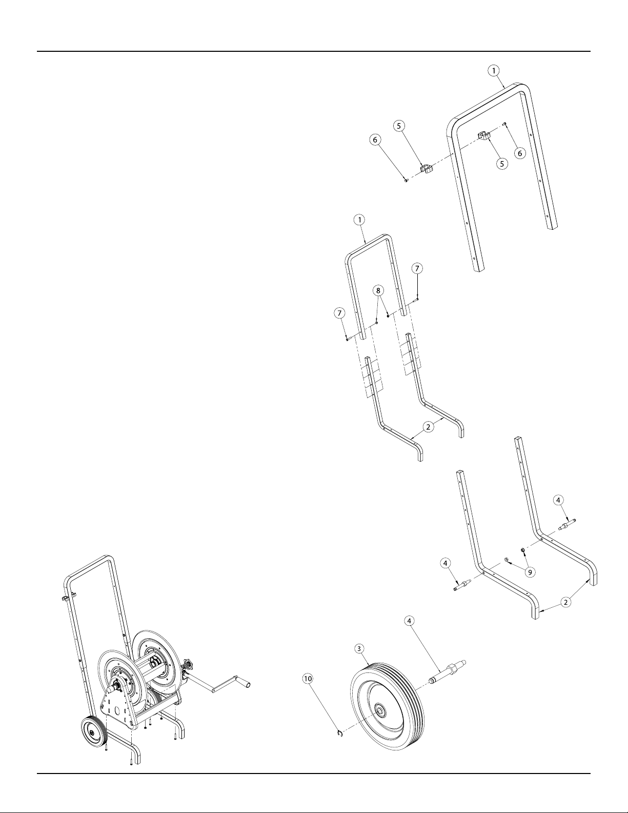
1. As shown in figure 1, find handle (1) and locate 0.156 thru
hole near the bend in the handle. Attach two gripper clips
(5) to handle (1) using two self-tapping screws (6).
2. As shown in figure 2, attach legs (2) to handle (1) using
two hex cap screws (7) and two lock nuts (8). Set cart
height by choosing one of the four adjustment holes on
each leg.
3. As shown in figure 3, attach one universal axle (4) to each
leg (2) and secure using one locknut.
4. As shown in figure 4, add one wheel (3) to each axle (4)
and secure using one “E” retaining ring (10). Note: The “E”
retaining ring should be placed in the retaining ring groove
closest to the wheel.
5. As shown in figure 5, attach the reel to cart by placing the
reel on the cart and securing it with four hex cap screws
and four lock nuts. Make sure all bolted connections are
tight and secure.
Figure 1
Figure 2
Figure 3
Page 2
Figure 5
Figure 4
www.reelcraft.com
Page 3

Instrucciones de Operacion
Ensambles del Carro
600741-1 / 600741-2
600885-1 / 600885-2
Dimensiones
Lista de Partes
Ctd / Modelo
#
600741-1 600741-2
1 1 1 261493 Manija, Carreta
2 2 2 261494 Pierna, Carreta
2 0 260752 Rueda, Neumática
3
0 2 260644 Rueda, Semineumática
4 2 2 261492 Eje, Universal
5 2 2 261320 Grapa para Agarrar
6 2 2 S294-26
7 6 6 S2-57 Tornillo de Tapa Hexagonal
8 6 6 300107 Tuerca de Cerradura
9 2 2 S281-6 Tuerca de Pestaña Hexagonal
10 2 2 S142-50 Anillo de Retención “E”
Parte
No.
Descripcion
Tornillo de Autotaladro y de Derivación
Lista de Partes
Ctd / Modelo
#
600885-1 600885-2
1 1 1 261659 Manija, Carreta
2 2 2 261494 Pierna, Carreta
2 0 260752 Rueda, Neumática
3
0 2 260644 Rueda, Semineumática
4 2 2 261492 Eje, Universal
5 2 2 261320 Grapa para Agarrar
6 2 2 S294-26
7 6 6 S2-57 Tornillo de Tapa Hexagonal
8 6 6 300107 Tuerca de Cerradura
9 2 2 S281-6 Tuerca de Pestaña Hexagonal
10 2 2 S142-50 Anillo de Retención “E”
Parte
No.
Descripcion
Tornillo de Autotaladro y de Derivación
Reelcraft Industries, Inc. • 2842 E Business Hwy 30, Columbia City, IN 46725
Ph: 800-444-3134 / 260-248-8188 • Fax: 800-444-4587 / 260-248-2605
Customer Service: 855-634-9109 • reelcraft@reelcraft.com • www.reelcraft.com
Form# 1098-501 Rev: 8/2011
Page 4

Ensambles del Carro
APLICACIONES
Reelcraft ofrece dos modelos de carreta de mano. El Modelo
600741-1, tiene ruedas semineumáticas, y se puede usar con
cualquier carrete de manguera de serie 30000 con una anchura
de bobina de 12 pulgadas. El Modelo 600741-2, tiene ruedas
semineumáticas, y se puede usar con cualquier carrete de
manguera de serie 30000 con una anchura de bobina de 12
pulgadas. Estas son unidades ideales para aplicaciones de
mantenimiento de tierras, granja y rancho, lavado a presión,
control de insectos, soldadura, industrial, aire, y agua.
MONTAJE
Antes de comenzar cualquier montaje, inspeccione los materiales empacados para daños ocurridos durante el envio e integridad. Reporte cualquier discrepancia inmediatamente.
1. Encuentre la manija (1) y ubique 0.156 a través del agujero
cerca de la curvadura en la manija. Del modo que se muestra en la figura 1, conecte dos grapas para agarrar (2) a la
manija (1) usando dos tornillos de autoderivación (3).
2. Del modo mostrado en la figura 3, conecte un eje universal
(1) a cada pata (2) y asegure usando una tuerca de cerradura (3).
3. Del modo mostrado en la figura 2, conecte las patas (1) a
la manija (2) usando dos tornillos de tapa hexagonal (3) y
dos tuercas de cerradura (4). Establezca la altura de la carreta seleccionando uno de los cuato agujeros de ajuste en
cada pata.
4. Del modo mostrado en la figura 4, añada una rueda (1)
a cada eje (2) y asegure usando un anillo de retención E
(3). Nota: El anillo de retención E: se debería colocar en la
ranura de anillo de reteción más cercana.
5. Del modo mostrado en la figura 5, conecte el carrete a la
carreta colocando el carrete en la carreta y asegurándolo
con cuatro tornillos de tapa hexagonal y cuatro tuercas de
cerradura. Asegure que todas las conexiones fijadas con
pernos están apretadas y seguras.
Figura 1
Figura 2
Figura 3
Page 4
Figura 5
Figura 4
www.reelcraft.com
Page 5

Instructions D’Opération
Chariots
600741-1 / 600741-2
600885-1 / 600885-2
Dimensions
Liste de Pièces
Qty / Model
#
600741-1 600741-2
1 1 1 261493 Handle, cart
2 2 2 261494 Leg, cart
2 0 260752 Wheel, pneumatic
3
0 2 260644 Wheel, semi-pneumatic
4 2 2 261492 Axle, universal
5 2 2 261320 Clip, gripper
6 2 2 S294-26 Screw, self drilling & tapping
7 6 6 S2-57 Screw, hex cap
8 6 6 300107 Nut, lock
9 2 2 S281-6 Nut, hex flange
10 2 2 S142-50 Ring, “E” retaining
Part # Description
Liste de Pièces
Qty / Model
#
600885-1 600885-2
1 1 1 261659 Handle, cart
2 2 2 261494 Leg, cart
2 0 260752 Wheel, pneumatic
3
0 2 260644 Wheel, semi-pneumatic
4 2 2 261492 Axle, universal
5 2 2 261320 Clip, gripper
6 2 2 S294-26 Screw, self drilling & tapping
7 6 6 S2-57 Screw, hex cap
8 6 6 300107 Nut, lock
9 2 2 S281-6 Nut, hex flange
10 2 2 S142-50 Ring, “E” retaining
Part # Description
Reelcraft Industries, Inc. • 2842 E Business Hwy 30, Columbia City, IN 46725
Ph: 800-444-3134 / 260-248-8188 • Fax: 800-444-4587 / 260-248-2605
Customer Service: 855-634-9109 • reelcraft@reelcraft.com • www.reelcraft.com
Form# 1098-501 Rev: 8/2011
Page 6

Chariots
APPLICATIONS
Reelcraft offre deux modèles de chariot. Le Modèle 600741-1 a des
roues à bandage semi-pneumatique ; il peut être utilisé avec n’importe
quel dévidoir à tuyaux de série 30000 ayant une largeur de bobine de
12”. Le Modèle 600741-2 a des roues à bandage semi-pneumatique
; il peut être utilisé avec n’importe quel dévidoir à tuyaux de série
30000 ayant une largeur de bobine de 12”. Ce sont des appareils
idéaux pour l’entretien des parcs, les fermes et ranches, le lavage sous
pression, la lutte antiparasitaire, le soudage, les applications industrielles, pneumatiques et hydrauliques.
MONTAGE
Avant de commencer tout montage, veuillez inspecter les matières
d’emballage pour voir si les pièces expédiées sont endommagées et si
elles sont complètes. Signaler immédiatement tous désaccords.
1. Trouver la poignée (1) et déterminer l’emplacement du trou traversant de 0,156 près du coude de la poignée. Comme indiqué dans
la figure 1, attacher les deux (2) pinces à griffes à la poignée (1)
en utilisant deux vis autotaraudeuses (3).
2. Comme indiqué dans la figure 3, attacher un (1) essieu monté à
la cardan à chaque pied (2) et l’immobiliser en utilisant un écrou
de blocage (3).
3. Comme indiqué dans la figure 2, attacher les pieds (1) à la poignée (2) en utilisant deux vis à chapeau à six pans (3) et deux
écrous de blocage (4). Régler la hauteur de chariot en choisissant
l’un des quatre trous de réglage sur chaque pied.
4. Comme indiqué dans la figure 4, ajouter une roue (1) à chaque
essieu (2) et l’attacher de façon sûre en utilisant une bague de
retenue E (3). Note : La bague de retenue E doit être placée dans
la rainure de bague de retenue la plus proche de la roue.
5. Comme indiqué dans la figure 5, attacher le dévidoir au chariot
en plaçant le dévidoir sur le chariot et en l’attachant à l’aide de
quatre vis à chapeau à six pans et quatre écrous de blocage.
S’assurer que toutes les connexions boulonnées sont bien serrées
et sûres.
Figure 1
Figure 2
Figure 3
Page 6
Figure 5
Figure 4
www.reelcraft.com
 Loading...