

Page 1
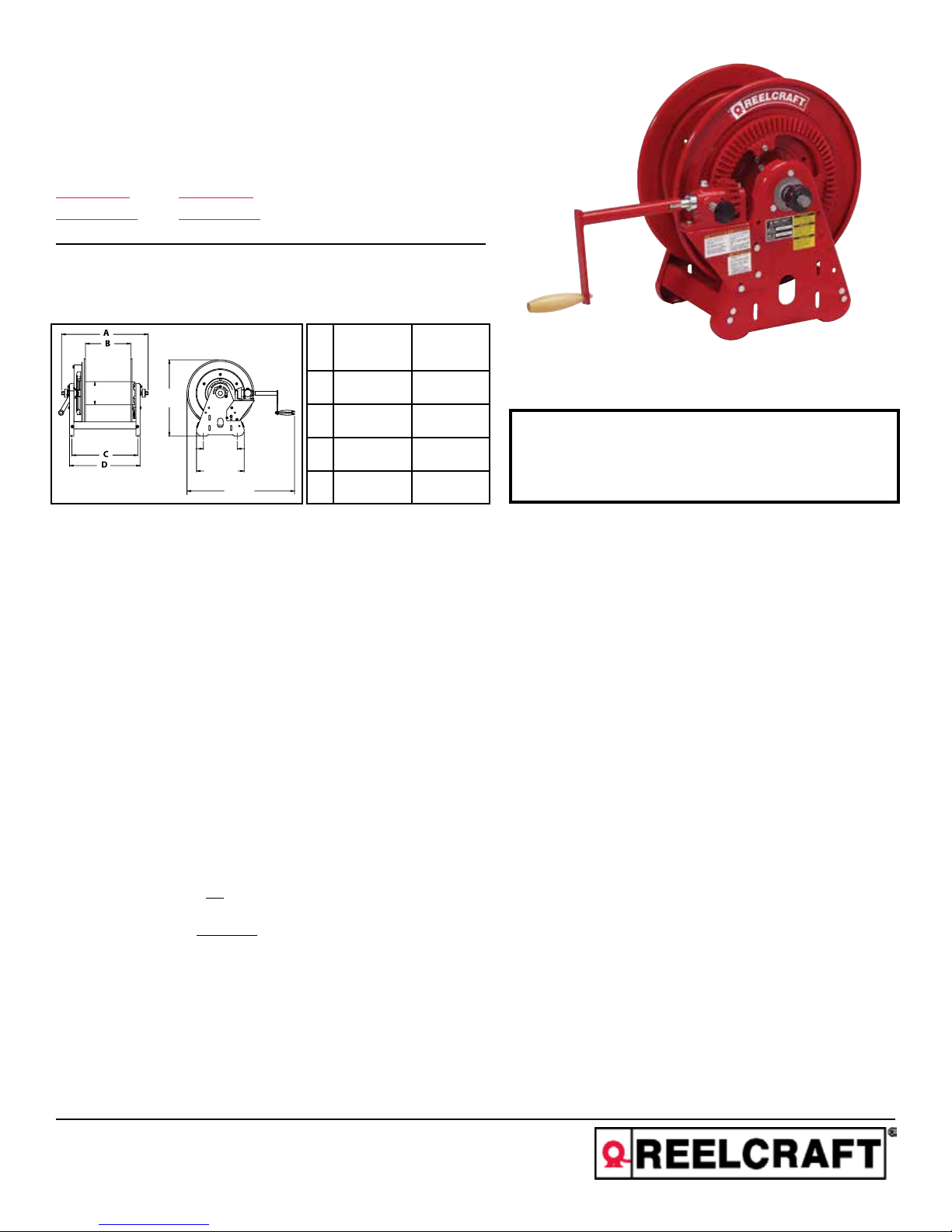
Operating Instructions
727 mm
Series BA30000 Welding Hose Reels
Low Pressure Model Numbers:
BA36106 L BA36112 L
BA36106 LT BA36112 LT
Dimensions
6 5/8”
170 mm
20 1/2”
514 mm
BA36106 L
BA36106 LT
A 15 5/8” 21 5/8”
BA36112 L
BA36112 LT
B 6” 12”
9”
229 mm
12 11/16”
320 mm
28 5/8”
C 9 3/4” 15 3/4”
D 11” 17”
Four 1/2” diameter mounting holes
SAFETY
Personal injury and/or equipment damage may result if proper safety
precautions are not observed.
• Ensure that reel is properly installed before connecting input and output
hoses.
• Bleed fluid/gas pressure from system before servicing reel.
• Before connecting reel to supply line, ensure that pressure does not
exceed maximum working pressure rating of reel.
• Remember, even low pressure is very dangerous and can cause personal injury or death.
• Be aware of machinery and personnel in work area.
• If a leak occurs in the hose or reel, remove system pressure immediately.
IMPORTANT
Read this manual carefully before installing, operating
or servicing this equipment.
• A high tension spring assembly is contained within the reel. Exercise
extreme caution.
• Pull hose from reel by grasping the hose itself, not the control valve.
• Ensure that reel, hose, and equipment being serviced are
properly grounded. Use an ohmmeter to check ground
continuity.
• If reel ceases to unwind or rewind, remove system pressure immediately. Do not pull or jerk on hose!
• Treat and respect the hose reel as any other piece of machinery,
observing all common safety practices.
IN-SERVICE CAUTION:
• The user is cautioned not to shut off the fuel gas at the regulator or supply source first, as a flashback may result, and thereby damage the
hose.
• Users are cautioned specifically to shut off the gas at the torch first, and then at the regulator or supply source, to limit permeation of gas
through the hose wall. This should be done when the torch will not be used for periods in excess of 30 minutes.
• After the flame has been extinguished and the gas turned off at the supply source, it is recommended that any remaining gas be bled to minimize degradation of the rubber during long shutdowns.
• To prevent an accumulation or concentration of gas that could be explosive or otherwise harmful to personnel, adequate ventillation must be
provided at all times, particularly in confined areas where fuel gas is being used.
• Additional advice for minimizing the permeation problem has been supplied by an NWSA member who states “The source of gas (fuel gas
and oxygen) should be closed before leaving for the day or shift. After the cylinder or manifold valves have been closed, the torch valves
(both fuel gas and oxygen) should be opened to remove all pressure from hoses.
Reelcraft Industries, Inc. • 2842 E Business Hwy 30, Columbia City, IN 46725
Ph: 800-444-3134 / 260-248-8188 • Fax: 800-444-4587 / 260-248-2605
Customer Service: 855-634-9109 • reelcraft@reelcraft.com • www.reelcraft.com
Form# 834-696E Rev: 10/2018
Page 2
Series BA30000 Welding Hose Reels
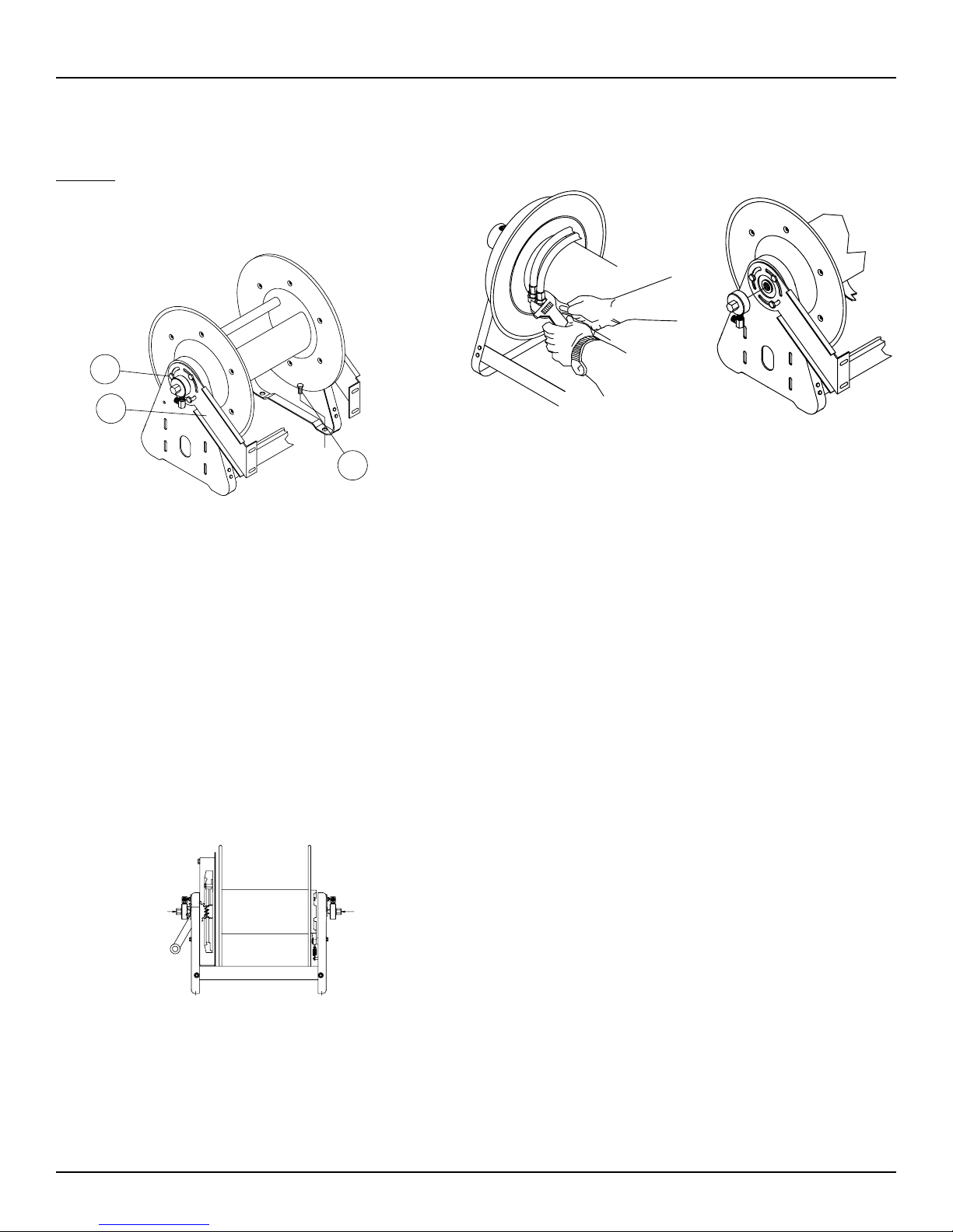
INSTALLATION INSTRUCTIONS
MOUNTING
Caution: Unless reel was specified differently when ordering,
maximum installation height is 16 feet. Do not exceed this distance. Observe all applicable NEC, OSHA & local codes when
installing this equipment.
1
2
3
1. Unpack and inspect reel for damage. Turn by hand to
check for smooth operation. Check for completeness.
2. Configure reel for top, side, or bottom-wind hose dispensing by removing bolts (or nuts) (1) securing guide arm
bracket (2).
3. Determine new guide arm bracket location and remove
corresponding bolts, (or nuts). Position guide arm bracket
to reel and replace bolts (or nuts).
4. Position reel on floor, wall or ceiling. Secure into place
using four (customer supplied) screws or bolts (3).
INSTALLING THE INPUT HOSES
Caution: Apply teflon tape to all input connections to insure
a proper seal.
2. Route output hoses through guide bracket.
3. Using a wrench, firmly hold on to fittings on shaft while
tightening the hose connector (see figure 1).
Figure 2
Figure 1
SERVICE INSTRUCTIONS
User servicing of the reel is limited to replacing the input/
output hoses or swivel only. Refer all other repairs to an authorized service person or directly to Reelcraft Industries, Inc.
Failure to do so can result in personal injury and/or equipment
damage and may void the warranty.
Caution: Rewind hose on reel, then bleed pressure from system before performing the following procedures.
1. Replace hoses in accordance with procedures given in
“Installation Instructions” section of this manual.
REPLACING THE SWIVEL
Caution: Remove supply line pressure before performing the
following procedure.
1. Remove supply line from swivel.
2. Remove swivel assembly from inlet shaft (see figure 2).
3. Apply thread sealant to threaded connection and re-install
swivel assembly to inlet shaft by reversing steps 1 & 2.
ADJUSTMENTS
Acetylene/fuel gas
inlet 1/4” FPT
(Red)
INSTALLING THE OUTPUT HOSES
Caution: Use extreme caution; reel under tension, avoid
releasing latch mechanism. Apply teflon tape to outlet connections.
1. Manually turn spool ass’y until spring is tight, back off
three turns, then latch.
Page 2
Oxygen inlet
1/4” FPT (Green)
Caution: Use extreme caution; reel under tension. Avoid
releasing latch mechanism. If necessary, adjust spring tension
of reel by adding or removing wraps of hose from spool, one
wrap at a time, until desired tension is obtained. Add wraps
to increase tension. Remove wraps to decrease tension. When
adding wraps of hose, be careful not to exceed the winding
mechanisms spring capacity. Add just enough wraps of hose to
achieve the desired tension. Damage to the winding mechanism
will result if spring is over-tensioned.
www.reelcraft.com
Page 3
Series BA30000 Welding Hose Reels
3
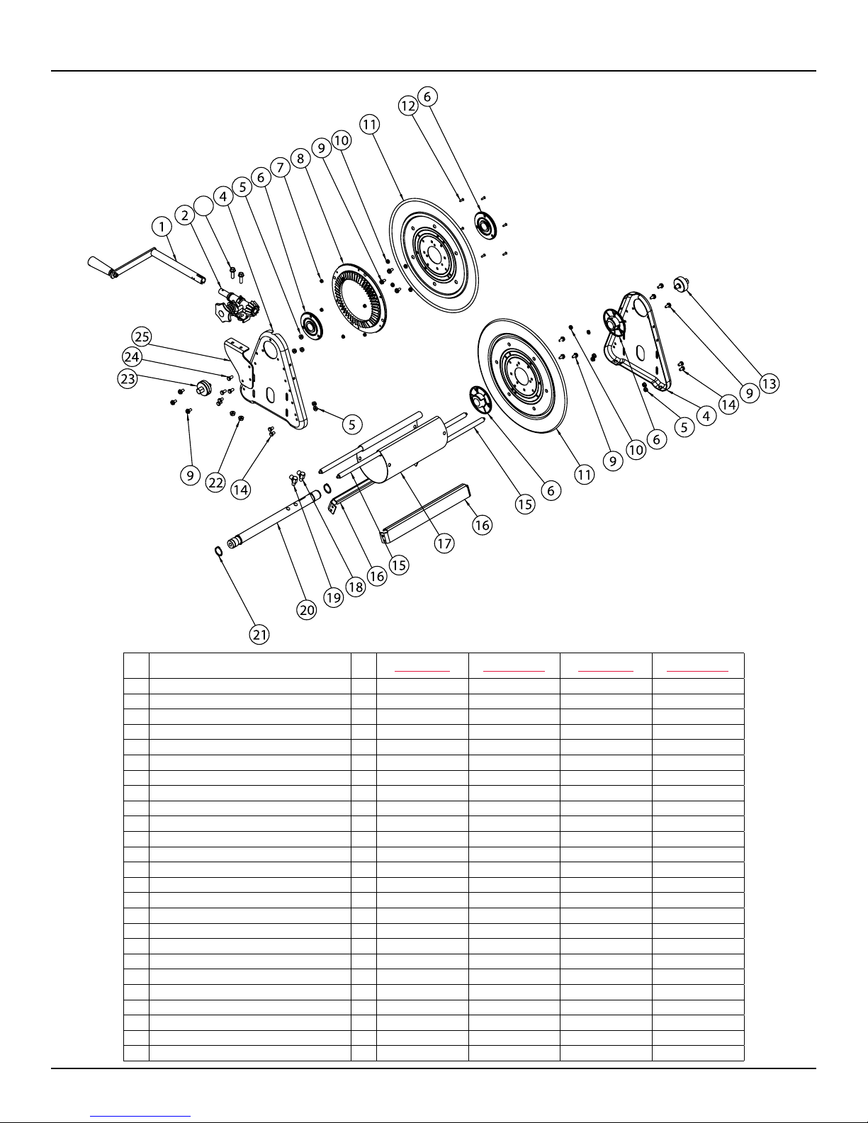
Item
#
1 Crank & Handle Assembly 1 S390838-10-35 S390838-10-35 S390838-10-35 S390838-10-35
2 Hand Rewind Assembly 1 S390843-2-ANZ S390843-2-ANZ S390843-2-ANZ S390843-2-ANZ
3 Hex Flange Screw (3/8-16 X 1-1/4) 2 S44-6 S44-6 S44-6 S44-6
4 Side Frame 2 260403 260403 260403 260403
5 Whiz Lock Nut (5/16-18) 11 300107 300107 300107 300107
6 Hub & Bushing Ass'y 4 S600640 S600640 S600640 S600640
7 Flange Nut (10-32) 6 S79-3 S79-3 S79-3 S79-3
8 Bevel Gear 1 S323058M-ANZ S323058M-ANZ S323058M-ANZ S323058M-ANZ
9 Self Tapping Screw (5/16-12 x 5/8) 12 S317-31 S317-31 S317-31 S317-31
10 Nyloc Nut (5/16-18) 8 S85-7 S85-7 S85-7 S85-7
11 Spool Flange 2 S260399-3 S260399-3 S260399-3 S260399-3
12 Flt Cap Socket Head Screw (10-32 X 5/8) 6 S27-108 S27-108 S27-108 S27-108
13 Swivel Assembly (Oxygen) 1 600257-3 600257-1 600257-3 600257-1
14 Hex Cap Screw (5/16-18 X 1/2) 8 S2-51 S2-51 S2-51 S2-51
15 Tie Rod 4 260402-1 260402-1 260402-2 260402-2
16 Cross Brace 2 261501-1 261501-1 261501-2 261501-2
17 Spool Spacer 1 260401-1 260401-1 260401-2 260401-2
18 Ell 90° (Oxygen) 1 S300091 S300091 S300091 S300091
19 Ell 90° (Acetylene) 1 S300090 S300090 S300090 S300090
20 Center Shaft 1 260649-1 260649-1 260649-2 260649-2
21 Snap Ring (1-1/4) 4 300007 300007 300007 300007
22 Hex Flange Nut (3/8-16) 2 S281-6 S281-6 S281-6 S281-6
23 Swivel Assembly (Acetylene) 1 600256-1 600256-1 600256-1 600256-1
24 Hex Cap Screw (5/16-18 X 5/8) 2 S2-52 S2-52 S2-52 S2-52
25 Crank Support Bracket 1 262344 262344 262344 262344
Description
#
BA36106 L BA36106 LT BA36112 L BA36112 LT
Req
www.reelcraft.com
Page 3
Page 4

727 mm
Instrucciones de Operación
Series BA30000 Carretes Dobles para Soldadura
Baja presion modelos y numeros:
BA36106 L BA36112 L
BA36106 LT BA36112 LT
Dimensions
6 5/8”
170 mm
20 1/2”
514 mm
BA36106 L
BA36106 LT
A 15 5/8” 21 5/8”
BA36112 L
BA36112 LT
B 6” 12”
9”
229 mm
12 11/16”
320 mm
28 5/8”
C 9 3/4” 15 3/4”
D 11” 17”
Cuatro huecos de ensablaje 1/2
Seguridad
Si no se observan las precauciones adecuadas de seguridad, pueden producirse lesiones personales y/o daños al equipo.
• Antes de conectar las mangueras de entrada y de salida, asegúrese
de que el carrete esté instalado correctamente.
• Antes de prestar servicio al carrete, descargue la presión de líquido/
gas del sistema.
• Antes de conectar el carrete a la línea de suministro, asegúrese de
que la presión no supere la especificación de presión máxima de
funcionamiento del carrete.
• Recuerde: aun la baja presión es muy peligrosa, y puede provocar
daños personales o la muerte.
• Manténgase al tanto de la presencia de máquinas y personal en la
zona de trabajo.
• Si se produce una fuga en la manguera o en el carrete, quite la presión al sistema de inmediato.
IMPORTANTE
Lea este manual cuidadosamente antes de
instalar, manejar o reparar este equipo.
• Dentro del carrete puede estar contenida una unidad de resorte de
alta tensión. Tenga extremo cuidado.
• Extraiga la manguera del carrete aferrando la manguera misma, no la
válvula de control.
• Asegúrese de que el carrete, la manguera y los equipos a los que se
está dando servicio, estén correctamente puestos a tierra. Verifique la
continuidad de la puesta a tierra mediante un óhmetro.
• Si el carrete cesa de desenrollarse o rebobinarse, quite la presión al
sistema de inmediato. ¡No dé tirones o sacudidas a la manguera!
• Trate y respete al carrete de manguera como a cualquier otro
elemento de maquinaria, observando todos los procedimientos
comunes de seguridad.
PRECAUCIÓN EN EL TRABAJO:
• Se advierte al usuario que no cierre primero el gas combustible en el regulador o la fuente de suministro, ya que podría producirse un retroceso
de la llama, y por lo tanto, un daño a la manguera.
• Se advierte específicamente a los usuarios que cierren primero el gas en el soplete, y luego en el regulador o fuente de suministro, para limitar la
permeación (paso) del gas a través de la pared de la manguera. Esto debe realizarse cuanto el soplete no se utilizará durante periodos mayores de
30 minutos.
• Después de haber apagado la llama y cerrado el gas en la fuente de suministro, se recomienda purgar cualquier gas restante para reducir al mínimo la degradación del caucho durante las paradas prolongadas.
• Para evitar una acumulación o concentración de gas que pudiera ser explosiva o dañina de otra manera para el personal, debe suministrarse ventilación adecuada a todo momento, especialmente en áreas encerradas donde se esté utilizando el gas combustible.
• Un miembro de la NWSA ha suministrado una recomendación adicional para reducir al mínimo el problema de permeación: “la fuente de gas (gas
combustible y oxígeno) debe cerrarse antes de salir después del día de trabajo o turno. Después de haber cerrado las válvulas del cilindro o del
múltiple, las válvulas del soplete (tanto la válvula de gas combustible como la válvula de oxígeno) deben abrirse para eliminar toda la presión de
las mangueras.
Reelcraft Industries, Inc. • 2842 E Business Hwy 30, Columbia City, IN 46725
Ph: 800-444-3134 / 260-248-8188 • Fax: 800-444-4587 / 260-248-2605
Customer Service: 855-634-9109 • reelcraft@reelcraft.com • www.reelcraft.com
Form# 834-696E Rev: 10/2018
Page 5

Series BA30000 Carretes Dobles para Soldadura
Instrucciones de Instalación
Montaje
ATENCIÓN: A menos que el carrete se hubiera especificado de
manera diferente al pedirlo, la máxima altura de la instalación
es 4.88 m (16 pies). No supere esta distancia.
1
2
3
1. Desempaque e inspeccione el carrete para verificar que
no esté dañado. Hágalo girar manualmente para verificar
que su funcionamiento sea suave y sin impedimentos.
Verifique que esté completo.
2. Configure el carrete para salida de la manguera enrollada
hacia arriba, hacia un lado o hacia abajo, quitando los
pernos (1A) y afloje los pernos (1B) en ambos lados del
carrete.
3. Determine la nueva ubicación del soporte del brazo guía, y
quite los pernos o tuercas correspondientes. Posicione el
soporte del brazo guía en el carrete, y vuelva a colocar los
pernos o tuercas.
4. Posicione el carrete en el piso, la pared o el cielorraso.
Asegúrelo en su posición utilizando cuatro tornillos o pernos (3) (a suministrar por el cliente).
Instalación de las mangueras de entrada
ATENCIÓN: Aplique cinta de teflon a todas las conexiones
de entrada para asegurar un cierre correcto.
Entrada de
acetileno/gas
combustible, 6.4
mm (1/4”) FPT
(Rojo)
Instalación de las mangueras de salida
ATENCIÓN: Tenga extremo cuidado; carrete bajo tensión.
Evite liberar el mecanismo de retención. Aplique cinta de teflon
a las conexiones de salida.
1. Haga girar manualmente el conjunto de la bobina hasta
que el resorte esté tenso, retroceda tres vueltas y luego
Entrada de
oxígeno: 6.4 mm
(1/4”) FPT
(Verde)
sujete.
2. Encamine las mangueras de salida a través del soporte
guía (figura 1).
3. Mediante una llave, sostenga firmemente los adaptadores
del eje mientras aprieta el conector de la manguera.
Figura 2
Figura 1
Instrucciones de Servicio
El servicio que el usuario puede prestar al carrete se limita
únicamente al reemplazo de las mangueras de entrada/salida o
la rótula. Dirija todas las demás reparaciones a una persona de
servicio autorizada, o directamente a Reelcraft Industries, Inc.
Si no lo hace pueden producirse lesiones personales y/o daños
a los equipos, y puede anular la garantía.
ATENCIÓN: rebobine la manguera en el carrete, y luego
purgue la presión del sistema antes de ejecutar los procedimientos siguientes:
1. Reemplace las mangueras de acuerdo con los procedimientos indicados en la sección ‘Instrucciones de instalación’ de este manual.
Reemplazo de la Rótula
ATENCIÓN: Quite la presión de la línea de suministro antes
de ejecutar el procedimiento siguiente.
1. Retire de la rótula la línea de suministro.
2. Extraiga del eje de entrada el conjunto de la rótula.
3. Aplique sellador de roscas a la conexión roscada, y vuelva
4. a instalar el conjunto de la rótula en el eje de entrada
invirtiendo los pasos 1 y 2 (figura 2).
Adjustes
ATENCIÓN: Tenga extremo cuidado; carrete bajo tensión.
Evite liberar el mecanismo de retención. Si fuera necesario,
ajuste la tensión del resorte del carrete añadiendo o quitando
vueltas de manguera de la bobina, de a una por vez, hasta
obtener la tensión deseada. Añada vueltas para aumentar la
tensión. Quite vueltas para disminuir la tensión. Cuando añada
vueltas de manguera, cuide de no superar la capacidad del
resorte del mecanismo de enrollado. Añada sólo la cantidad
suficiente de vueltas para alcanzar la tensión deseada. Si el
resorte se tensiona en exceso, se dañará el mecanismo de
enrollado.
Page 5
www.reelcraft.com
Page 6

Series BA30000 Carretes Dobles para Soldadura
3
Ítem
N°
1 Manivela y montaje maneta 1 S390838-10-35 S390838-10-35 S390838-10-35 S390838-10-35
2 Montaje de rebobinado Mano 1 S390843-2-ANZ S390843-2-ANZ S390843-2-ANZ S390843-2-ANZ
3 Hex tornillo brida (3/8-16 X 1-1/4) 2 S44-6 S44-6 S44-6 S44-6
4 Bastidor lateral 2 260403 260403 260403 260403
5 Whiz tuerca de seguridad (5/16-18) 11 300107 300107 300107 300107
6 Conjunto de cubo y buje 4 S600640 S600640 S600640 S600640
7 Brida Tuerca (10-32) 6 S79-3 S79-3 S79-3 S79-3
8 Engranaje cónico 1 S323058M-ANZ S323058M-ANZ S323058M-ANZ S323058M-ANZ
9 Tornillo autorroscante (5/16-12 x 5/8) 12 S317-31 S317-31 S317-31 S317-31
10 Tuerca Nyloc (5/16-18) 8 S85-7 S85-7 S85-7 S85-7
11 Brida de la bobina 2 S260399-3 S260399-3 S260399-3 S260399-3
12 Socket fit tapa tornillo de cabeza (10-32 X 5/8) 6 S27-108 S27-108 S27-108 S27-108
13 Conjunto de rótula (oxígeno) 1 600257-3 600257-1 600257-3 600257-1
Tornillo de casquillo del maleficio (5/16-18 x 1/2)
14
15 Tensor 4 260402-1 260402-1 260402-2 260402-2
16 Refuerzo transversal 2 261501-1 261501-1 261501-2 261501-2
17 Espaciador de bobina 1 260401-1 260401-1 260401-2 260401-2
18 Ell 90° (oxígeno) 1 S300091 S300091 S300091 S300091
19 Ell 90° (acetileno) 1 S300090 S300090 S300090 S300090
20 Centro del eje 1 260649-1 260649-1 260649-2 260649-2
21 Anillo de retención (1-1/4") 4 300007 300007 300007 300007
22 Hex tuerca de brida (3/8-16) 2 S281-6 S281-6 S281-6 S281-6
23 Conjunto de rótula (acetileno) 1 600256-1 600256-1 600256-1 600256-1
Tornillo de casquillo del maleficio (5/16-18 x 5/8)
24
25 Soporte inestable 1 262344 262344 262344 262344
DESCRIPCIÓN
No.
BA36106 L BA36106 LT BA36112 L BA36112 LT
Req
8 S2-51 S2-51 S2-51 S2-51
2 S2-52 S2-52 S2-52 S2-52
www.reelcraft.com
Page 6
Page 7

Instructions d’utilisations
727 mm
Sèrie BA30000 Dèvidoirs doubles pour soudage
Basse pression numéros de modèle:
BA36106 L BA36112 L
BA36106 LT BA36112 LT
Dimensions
6 5/8”
170 mm
20 1/2”
514 mm
BA36106 L
BA36106 LT
A 15 5/8” 21 5/8”
BA36112 L
BA36112 LT
B 6” 12”
9”
229 mm
12 11/16”
320 mm
28 5/8”
C 9 3/4” 15 3/4”
D 11” 17”
4 trous de montage de diametre 1/2”
Sécurité
Des blessures corporelles et/ou des dégâts matériels peuvent survenir si des
précautions de sécurité adéquates ne sont pas observées.
• Assurez-vous que le dévidoir est correctement installé avant d’y connecter des tuyaux d’arrivée et de sortie.
• Purgez la pression de gaz/fluide du système avant d’intervenir sur le
dévidoir.
• Avant de brancher le dévidoir sur la conduite d’alimentation, assurezvous que la pression ne dépasse pas la pression de service maximum que peut admettre le dévidoir.
• Souvenez-vous que même de la basse pression est très dangereuse
et peut causer des blessures graves voire mortelles.
• Soyez conscient de la présence de machines et de personnes dans la
zone de travail.
• En cas de fuite du tuyau ou du dévidoir, relâchez immédiatement la
pression du système.
IMPORTANT
Lire attentivement ce manuel avant
d’installer, utiliser ou dépanner cet équipment.
• Un dispositif sous forte tension peut être intégré dans le dévidoir.
Faites très attention.
• Tirez le tuyau hors du dévidoir en prenant le tuyau lui-même, pas sa
vanne de commande.
• Assurez-vous que dévidoir, tuyau et équipement sur lesquels vous
intervenez sont correctement mis à la terre. Utilisez un ohmmètre
pour vérifier la continuité à la terre.
• Si le dévidoir cesse d’enrouler ou dérouler, relâchez immédiatement
la pression du système. Ne tirez pas en force sur le tuyau et ne le
secouez pas!
• Traitez avec respect le dévidoir comme tout autre outil de travail, en
respectant les pratiques de base de sécurité.
PRÉCAUTIONS DURANT LE SERVICE :
• L’utilisateur est avisé de ne pas couper le gaz carburant en premier au niveau du régulateur ou de la source d’alimentation, il pourrait en
résulter un retour de flamme qui endommagerait le tuyau.
• L’utilisateur est spécifiquement informé qu’il lui faut couper le gaz en premier au niveau du chalumeau, et seulement après au niveau du
régulateur ou de la source d’alimentation, pour limiter la pénétration du gaz au travers de la paroi de tuyau. Il faut le faire quand le chalumeau
n’est pas utilisé pour des périodes dépassant 30 minutes.
• Une fois la flamme atteinte et le gaz coupé à l’alimentation en amont, il est recommandé de souffler tout le gaz rémanent pour minimiser la
dégradation du caoutchouc durant les longues coupures.
• Pour éviter une accumulation ou concentration de gaz qui pourrait être une source d’explosion ou de danger pour le personnel, une ventilation adéquate doit être fournie en permanence, en particulier dans les zones confinées où du gaz combustible est utilisé.
• Un conseil complémentaire pour minimiser le problème de pénétration a été fourni par un membre de la NWSA : La source de gaz (gaz combustible et oxygène) doit être fermée avant de partir en fin de journée ou de quart. Une fois fermés bouteilles ou robinets de distribution, les
robinets du chalumeau (gaz combustible et oxygène) doivent être ouverts à nouveau pour évacuer la pression des tuyaux.
Reelcraft Industries, Inc. • 2842 E Business Hwy 30, Columbia City, IN 46725
Ph: 800-444-3134 / 260-248-8188 • Fax: 800-444-4587 / 260-248-2605
Customer Service: 855-634-9109 • reelcraft@reelcraft.com • www.reelcraft.com
Form# 834-696E Rev: 10/2018
Page 8

Sèrie BA30000 Dèvidoirs doubles pour soudage
Instructions d’installation
Montage
ATTENTION : Sauf si le dévidoir avait été spécifié différemment
à sa commande, la hauteur maximale pour son installation
est de 16’ (4,9 m). Ne dépassez pas cette longueur. Observez
toutes les normes applicables, NEC, OSHA et locales, pour
l’installation de cet équipement.
1
2
3
1. Déballez et inspectez le dévidoir pour chercher d’éventuels
dommages. Faites-le tourner manuellement pour contrôler
l’absence de blocage. Vérifiez que le produit est complet.
2. Configurez le dévidoir pour la configuration de sortie de
tuyau vers le haut, le côté ou le bas, en ôtez les boulons
(1A) et desserrez les boulons (1B) de chaque côté du dévidoir.
3. Déterminez le nouvel emplacement pour le support de bras
de guidage et enlevez les boulons (ou écrous) correspondants. Positionnez le support de bras de guidage sur le
dévidoir et remettez en place ses boulons (ou écrous).
4. Positionnez le dévidoir sur sol, mur ou plafond. Fixez-le
en place en utilisant quatre vis ou boulons et chevilles
d’ancrage de fourniture locale (3).
Installation des tuyaux d’entrée
ATTENTION : Appliquez de la bande téflon sur tous les
raccordements d’entrée pour assurer une bonne étanchéité.
Entrée de gaz
acétylène/carburant
en 1/4” FPT
(Rouge)
Installation des tuyaux de sortie
ATTENTION : Faites très attention, le dévidoir est tendu,
évitez de relâcher le mécanisme de verrouillage. Appliquez de
la bande téflon sur les raccordements de sortie.
1. Faites tourner à la main le tambour du dévidoir jusqu’à
ce que le ressort soit tendu, revenez de trois tours et ver-
Entrée
d’oxygène
en 1/4” FTP
(Vert)
rouillez.
2. Faites passer les tuyaux de sortie au travers du support de
guidage (figure 1).
3. En utilisant une clé, maintenez fermement les raccords sur
l’arbre tout en serrant le connecteur de tuyau.
Figure 2
Figure 1
Instructions de service
Les interventions de l’utilisateur sur le dévidoir sont limitées au
remplacement des tuyaux d’entrée ou de sortie, ou du pivot.
Confiez toutes les autres réparations à un agent de service
agréé, ou directement à Reelcraft Industries, Inc. Sinon vous
risquez des blessures corporelles et/ou des dommages sur
l’équipement, et cela peut annuler la garantie.
ATTENTION : Enroulez le tuyau sur le dévidoir, puis relâchez
la pression du système avant d’exécuter les procédures qui
suivent.
1. Remplacez les tuyaux en conformité avec les procédures
données dans la section Instructions d’installation de ce
manuel.
Remplacement du pivot
ATTENTION : Relâchez la pression de la conduite
d’alimentation avant d’exécuter la procédure qui suit.
1. Enlevez la conduite d’alimentation du pivot (figure 2).
2. Déposez l’ensemble de pivot de l’arbre d’entrée.
3. Appliquez un produit d’étanchéité sur les filets de raccordement et remonter un ensemble de pivot sur l’arbre
d’entrée en procédant à l’inverse des étapes 2 et 1.
Réglages
ATTENTION : Faites très attention, le dévidoir est tendu,
évitez de relâcher le mécanisme de verrouillage. Si nécessaire,
réglez la tension du ressort en ajoutant ou en enlevant des
tours de tuyau au dévidoir, un tour à la fois, jusqu’à ce que la
tension voulue soit obtenue. Ajoutez des tours pour augmenter
la tension, enlevez-en pour la diminuer. Quand vous ajoutez
des tours sur le dévidoir, veillez à ne pas dépasser la capacité
du ressort de mécanisme d’enroulement. Ajoutez juste assez de
tours de tuyau pour obtenir la bonne tension. Des dommages
au mécanisme d’enroulement peuvent amener une tension
excessive du ressort.
Page 8
www.reelcraft.com
Page 9

Sèrie BA30000 Dèvidoirs doubles pour soudage
3
N° DE
RÉF
1 Ensemble de manivelle et poignée 1 S390838-10-35 S390838-10-35 S390838-10-35 S390838-10-35
2 Main ensemble d’enroulement 1 S390843-2-ANZ S390843-2-ANZ S390843-2-ANZ S390843-2-ANZ
3 Hex Bride Vis (3/8-16 X 1-1/4) 2 S44-6 S44-6 S44-6 S44-6
4 Bâti de côté 2 260403 260403 260403 260403
5 Whiz écrou (5/16-18) 11 300107 300107 300107 300107
6 Ensemble de moyeu et bague 4 S600640 S600640 S600640 S600640
7 Écrou de bride (10-32) 6 S79-3 S79-3 S79-3 S79-3
8 Engrenage conique 1 S323058M-ANZ S323058M-ANZ S323058M-ANZ S323058M-ANZ
9 Auto-fileteux Vis (5/16-12 x 5/8) 12 S317-31 S317-31 S317-31 S317-31
10 Écrou de Nyloc (5/16-18) 8 S85-7 S85-7 S85-7 S85-7
11 Joue de poulie 2 S260399-3 S260399-3 S260399-3 S260399-3
12 Monter cap vis à tête creuse (10-32 X 5/8) 6 S27-108 S27-108 S27-108 S27-108
13 Ensemble de pivot (oxygène) 1 600257-3 600257-1 600257-3 600257-1
14 Vis de chapeau de sortilège (5/16-18 x 1/2) 8 S2-51 S2-51 S2-51 S2-51
15 Tige d’accouplement 4 260402-1 260402-1 260402-2 260402-2
16 Entretoise 2 261501-1 261501-1 261501-2 261501-2
17 Entretoise de dévidoir 1 260401-1 260401-1 260401-2 260401-2
18 Ell 90° (oxygène) 1 S300091 S300091 S300091 S300091
19 Ell 90° (acétylène) 1 S300090 S300090 S300090 S300090
20 Centre d’arbre 1 260649-1 260649-1 260649-2 260649-2
21 Circlip (1-1/4") 4 300007 300007 300007 300007
22 Hex écrou de bride (3/8-16) 2 S281-6 S281-6 S281-6 S281-6
23 Ensemble de pivot (acétylène) 1 600256-1 600256-1 600256-1 600256-1
24 Vis de chapeau de sortilège (5/16-18 x 5/8) 2 S2-52 S2-52 S2-52 S2-52
25 Support détraqué 1 262344 262344 262344 262344
Description QTÉ
BA36106 L BA36106 LT BA36112 L BA36112 LT
www.reelcraft.com
Page 9
 Loading...