

Page 1
Operating Instructions
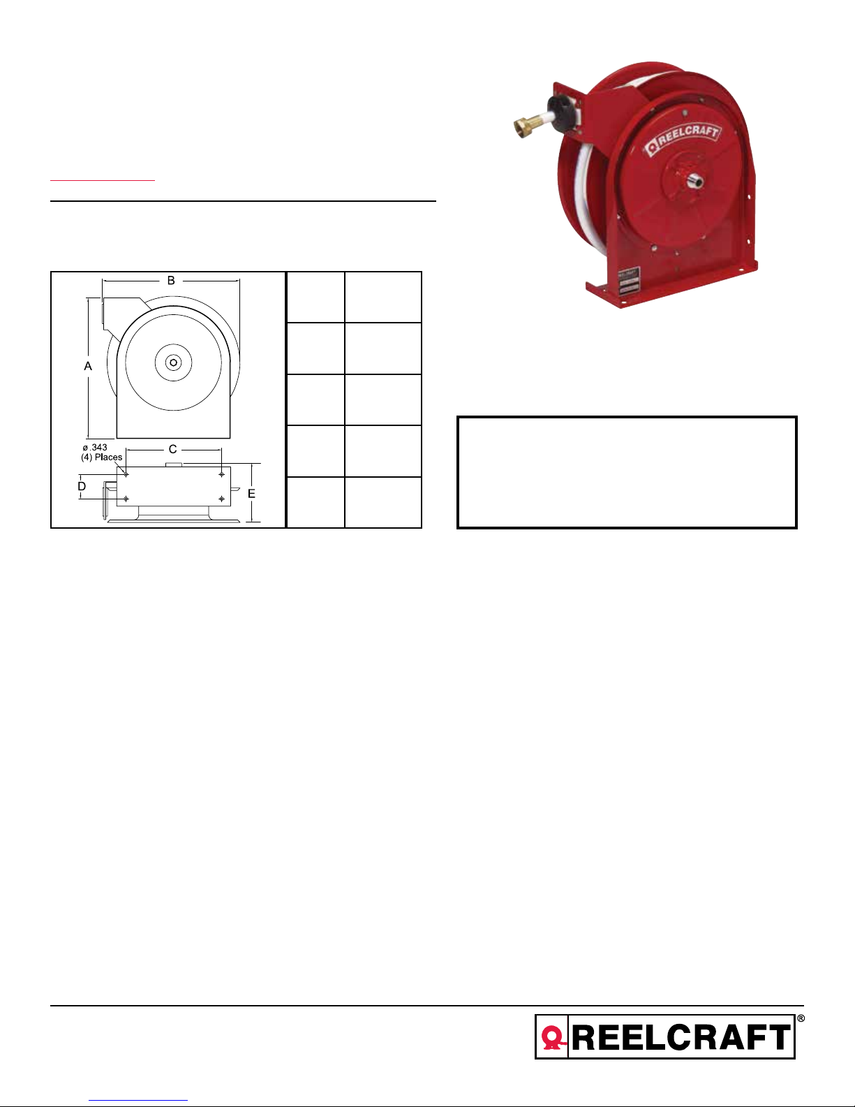
Series 5000 Spring Driven Hose Reels
Low Pressure Potable (Drinking) Water Reel:
A5835 OLBSW23
Dimensions
A 14 3/8”
B 14”
C 9 3/4”
INSTALLATION:
MOUNTING:
LUBRICATION:
REPLACING HOSE:
D 2 1/2”
E 6 1/8”
A flexible hose connection must be used between the hose reel inlet and the source of supply to prevent possible
misalignment and binding.
The hose reel is equipped with a universal mounting bracket so that it can be mounted on the floor, wall or
ceiling; whichever place is convenient. The hose guide arm can be moved to the position desired by removing
the screws fastening the guide bracket to the reel base. Shift the guide arm bracket so the hose comes off the
reel at the desired position and replace the screws. NOTE: For proper installation in wall mount applications, ensure
reel is mounted with inlet on the right as you are facing the reel. Failing to do so could cause latching issues.
Hose reel spring and bearings are factory lubricated and require no further lubrication.
1. Wind spool flange clockwise-facing swivel-until spring is tight.
2. Back off three turns and latch.
3. Insert hose through roller guide.
4. Connect hose fitting to swivel joint and secure hose with clamps.
1. Do not use reel at higher pressures or temperatures than
listed on the back of this bulletin.
2. Remove all spring tension before beginning dissassembly
process.
SAFETY
ADJUSTMENTS:
REPAIRS:
Reelcraft Industries, Inc. • 2842 E Business Hwy 30, Columbia City, IN 46725
Ph: 800-444-3134 / 260-248-8188 • Fax: 800-444-4587 / 260-248-2605
Customer Service: 855-634-9109 • reelcraft@reelcraft.com • www.reelcraft.com
To adjust spring tension, add or remove wraps of hose from the spool, one wrap at a time until desired tension is
obtained.
Extensive repairs should be performed only by an authorized serviceman or factory to avoid damage which may
void your warranty. Remove all spring tension before beginning disassembly process.
Form# 720-994 Rev: 6/2018
Page 2

Series 5000 Spring Driven Hose Reels
5
4
3
2
1
33
31
30
32
11
17
16
15
10
14
13
12
9
8
7
6
18
19
20
21
22
23
24
25
26
29
2728
Item
Part #
#
1 300031 2 Snap Ring 18 S500103 1 Spring Case Assembly
2 300034 2 Spacing Washer 19 S82-15 1 10-32 x 3/8” Nyloc Nut
3 S295-102 3 1/4” Plastite Hex Screw 20 S400021 1 Latch Bumper
4 260022 1 Sheave Flange 21 S32-136 1 10-24 x 3/8” Mach. Screw
5 500006 1 Sheave Disc 22 S400012 1 Latch Bushing
6 S500019 1 Latch Cam 23 S400018 1 Latch Spring
7 S260648 1 Spring Arbor 24 300001 5 10-32 x 3/8” Screw
8 300002 2 10-32 x 1/2” Screw 25 400020 1 O’Ring
9 1-HR1004 1 Bumper Stop Assembly 26 S400109 1 Latch Plate Assembly
10 601062 1 Hose Assembly 27 300035 1 10-32 x 1” Mach. Screw
11 300062 1 Hose Plug 28 3-117440 1 U-bolt
12 S500107 1 Guide Arm & Roller Assembly 29 261650-1 2 1/4-20 Zinc Nyloc Nut
13 500101 1 Base Assembly 30 260765 1 Main Shaft
14 S300011 7 10-32 Hex Lock Nut 31 261845 1 90° Street Ell
15 S505740 1 Drive Spring Assembly 32 261846 1 Swivel Assembly
16 S261360 1 Spring Case Stud 33 S600999 1 Swivel & Ell Assembly
17 300006 1 3/8-16 x 1/2” Set Screw
#
Req.
Description
Hose I.D. & Length 1/2” x 35’
Reel Inlet Connection 1/2” M.P.T.
Max. Operating Pressure 300 P.S.I.
Max. Operating Temperature 210 °F
Item
#
Part #
#
Req.
Description
Reels prior to September 2009 used a hose and swivel that are now obsolete
but a seal kit is available for these reels - part number S600337-1.
Page 2
www.reelcraft.com
Page 3

Instrucciones de Operacion
Series 5000 Carreteles para Mangueras
Carrete (de consumición) potable del agua de la presión baja:
A5835 OLBSW23
Dimensions
A 14 3/8”
B 14”
C 9 3/4”
D 2 1/2”
E 6 1/8”
SEGURIDAD
1. No use carreteles a presiones o temperaturas altas que no se
mencionan en este boletin.
2. Remueva la tencion antes de empezar el proceso de desarme.
INSTALACION:
MONTAJE:
LUBRICACION:
REMPLAZO DE LA
MANGUERA:
AJUSTAMIENTO:
REPARACION:
Page 3
Una manguera flexible de coneccion tiene que ser usada entre la entrada de la manguera de el carretel y la fuente
de abastecimiento para prevenir un posible desalineamiento y enlazamiento.
El riel de manguera esta equipado con un soporte de montaje universal para que esta pueda ser montada en el
piso, pared o techo; cualquier sitio es conveniente. El brazo guia de la manguera puede ser movido a la posicion
deseada removiendo los tornillos firmemente de la guia de soporte de la base de el carretel. Posicione la guia de
soporte del brazo abra que la manguera quede afuera del carretel a la posicion deseada; y reemplaze los tornillos.
NOTA: Para la instalación apropiada en usos del montaje de la pared, asegúrese que el carrete esté montado con
la entrada a la derecha mientras que usted está haciendo frente al carrete. El no poder hacer tan podía causar el
enganche de ediciones.
El resorte del carretel de la manguera y el cojinete estan empacado con grasa y no requiere futura lubricacion.
1. De vueltas a la palanca giratoria hacia la derecha hasta que el resorte este apretado.
2. Devuelva 3 giros y asegure.
3. Inserte la manguera atravez de la guia del rodillo.
4. Conecte y encaje la manguera a la salida hembra de el codo de tuberia.
Para ajustar la tension del resorte en el carretel, agrege o quite vueltas hasta que la tension deseada es obtenidad.
Extensivas reparaciones deberan ser realizadas por una persona de servicio autorizada o por la fabrica para evitar
daños que eliminen su garantia. Remueva todos los resortes de tension antes del proceso de desmontaje.
Form# 720-994 Rev: 6/2018
Reelcraft Industries, Inc. • 2842 E Business Hwy 30, Columbia City, IN 46725
Ph: 800-444-3134 / 260-248-8188 • Fax: 800-444-4587 / 260-248-2605
Customer Service: 855-634-9109 • reelcraft@reelcraft.com • www.reelcraft.com
Page 4

Series 5000 Carreteles para Mangueras
5
4
3
2
1
33
31
30
32
11
17
16
15
10
14
13
12
9
8
7
6
18
19
20
21
22
23
24
25
26
29
2728
Arti
culo
Part #
1 300031 2 Aro de resorte 18 S500103 1 Ensamble de la caja del resorte
2 300034 2 Arendela espaciadora 19 S82-15 1 Tuerca de nyloc 10-32 x 3/8"
3 S295-102 3 Tornillo hex. plástico de 6,4 mm 20 S400021 1 Paragolpes de aldaba
4 260022 1 Brida de roldana 21 S32-136 1 Tornillo metales 10-24x3/8"
5 500006 1 Disco de roldana 22 S400012 1 Sujetador de aldaba
6 S500019 1 Leva de aldaba 23 S400018 1 Resorte de la Aldaba
7 S260648 1 Resorte de tambor 24 300001 5 Tornillo 10-32 x 3/8"
8 300002 2 10-32 x 1/2" tornillo 25 400020 1 Anillo en O
9 1-HR1004 1 Ensamble del paragolpes 26 S400109 1 Ensamble de la Placa de la Aldaba
10 601062 1 Ensamble de la manguera 27 300035 1 Torn. para metales 10-32 x 3/8"
11 300062 1 Tapón para mangueras 28 3-117440 1 Perno en U
12 S500107 1 Ensamble de brazo y rodillo guía 29 261650-1 2 Tuerca de Nyloc 1/4-20
13 500101 1 Ensamble de la base 30 260765 1 Eje principal
14 S300011 7 Tuerca de cierre, hexagonal 10-32 31 261845 1 Codo de servicio 90º
15 S505740 1 Ensamble del resorte de impulsión 32 261846 1 Ensamble de articulación giratoria
16 S261360 1 Perno de la caja del resorte 33 S600999 1 Ensamble de artic. y de ele
17 300006 1 Tornillo 3/8-16 x 12"
No
Req.
Descripcion
Dia. Inernoy Long. de Mangueras 1/2” x 35’
Conexión de Entdel Carretel 1/2” M.P.T.
Presión Mâx. de Operación 300 P.S.I.
Temp. Mâx. de Operación 210 °F
Arti
culo
Part #
Req.
No
Descripcion
Carretes previo a septiembre de 2009 utilizaron una manguera y giratoria que ahora son obsoletos,
sino un juego de juntas está disponible para estos carretes - número de pieza S600337-1.
Page 4
www.reelcraft.com
Page 5

Instructions D’Opération
Série 5000 Enrouleurs de Tuyau Manuels
Enrouleurs potable de l’eau de basse pression :
A5835 OLBSW23
Dimensions
A 14 3/8”
B 14”
C 9 3/4”
LA SÉCURITÉ
INSTALLATION:
MONTAGE:
LUBRIFICATION:
REMPLACEMENT
DE TUYAU:
D 2 1/2”
E 6 1/8”
Un raccord de tuyau flexible doit être utilisé entre l’entrée d’enrouleur et la source d’alimentation pour prévenir le
défaut d’alignment ou le coincement.
L’enrouleur de tuyau est équipé d’un support de montage universal pour être monté au plancher, au mur, ou au
plafond, quel que soit la position que vous désiriez. Le guide de tuyau peut être mis au position désiré en enlevant
les vis attachant le support guide au base de l’enrouleur. Positionez le support guide pour que le tuyau puis
enrouler de l’enrouleur comme désiré et remplacez les vis. NOTE : Pour l’installation appropriée dans des applications de bâti de mur, assurez que l’enrouleur est montée avec l’admission du côté droit pendant que vous faites
face à l’enrouleur. Ne pas faire ainsi a pu causer verrouiller des issues.
Le ressort de l’enrouleur et les pailers sont lubrifiés à vie en usine.
1. Enroulez la piéce d’espacement bridée dans le sens des aiguilles d’une montre (face au pivot) jusqu’ au ressort
est bien serré.
2. Faites marche arriére 3 tours, et puis fermez au loquet le mécanisme.
3. Insérez le tuyau à travers le guide et le trou de la pièce d’espacement bridée.
4. Connectez le raccord de tuyau au joint de pivot, et fixez le tuyau avec des crampons.
1. N’utillisez pas les enrouleurs à pression plus haut ou aux
températures plus hauts que ce qui est noté sur le dos de ce
bulletin.
2. Enlevez toute tension du ressort avant de désassembler.
RÉGLAGES:
RÉPARATIONS:
Page 5
Reelcraft Industries, Inc. • 2842 E Business Hwy 30, Columbia City, IN 46725
Ph: 800-444-3134 / 260-248-8188 • Fax: 800-444-4587 / 260-248-2605
Customer Service: 855-634-9109 • reelcraft@reelcraft.com • www.reelcraft.com
Pour régler la tension du ressort, ajoutez ou enlevez des tours de câble, un tour à la fois, jusqu’à l’obtention de la
tension désirée.
Des réparations étendues doivent être fait uniquement par un homme de service authorisé ou par l’usine pour éviter
le dommage quie peut annuler votre garantie. Enlevez toute tension de ressort avant de désassembler.
Form# 720-994 Rev: 6/2018
Page 6

Série 5000 Enrouleurs de Tuyau Manuels
6
5
4
3
2
1
33
31
30
32
11
17
16
15
10
14
13
12
9
8
7
18
19
20
21
22
23
24
25
26
29
2728
N°
d’article
1 300031 2 Circlip #1 18 S500103 1 Assemblage de boîtier de ressort
2 300034 2 Rondelle d’espacement 19 S82-15 1 Écrou poussoir 10-32 x 3/8"
3 S295-102 3 Vis hex.en plast.de 6,4 mm 20 S400021 1 Butée de loquet
4 260022 1 Collet en faisceau 21 S32-136 1 Vis usinée 10-24 x 3/8"
5 500006 1 Disque de poulie 22 S400012 1 Bague de loquet
6 S500019 1 Came de loquet 23 S400018 1 Ressort de loquet
7 S260648 1 Mandrin de ressort 24 300001 5 Vis 10-32 x 3/8"
8 300002 2 Vis de 10-32 x 1/2" 25 400020 1 Joint torique
9 1-HR1004 1 Assemblage du butoir 26 S400109 1 Plaque de loquet
10 601062 1 Vis usinée 27 300035 1 Vis usinée 10-32 x 1"
11 300062 1 Bouchon de tuyau 28 3-117440 1 Boulon en U
12 S500107 1 Bras deguid et ass. demuleaux 29 261650-1 2 Écrou Nyloc en Zinc 1/4-20
13 500101 1 Assemblage de la base 30 260765 1 Axe principal
14 S300011 7 Contre-écrou hex. 10-32 31 261845 1 Coude mâle et femelle 90º
15 S505740 1 Assemblage de ressort d'entr. 32 261846 1 Assemblage de pivot
16 S261360 1 Boulon de boîtier de ressort 33 S600999 1 Assemblage de pivot et de coude
17 300006 1 Vis de réglage 3/8-16-x 1/2"
N°de
pièce
N°
requis.
Déscription
Longueur et D.I. du tuyau 1/2” x 35’
Raccord d’entrée de l’enrouleur 1/2” M.P.T.
Pres. de fonctionnement maxi. 300 P.S.I.
Temp. de fonctionnement max 210 °F
N°
d’article
N°de
pièce
N°
requis.
Déscription
Enrouleurs préalable à Septembre 2009 utilisé un tuyau et pivotante qui sont maintenant obsolètes,
mais un kit d’étanchéité est disponible pour ces enrouleurs - numéro de pièce S600337-1.
Page 6
www.reelcraft.com
 Loading...