

Page 1
Operating Instructions
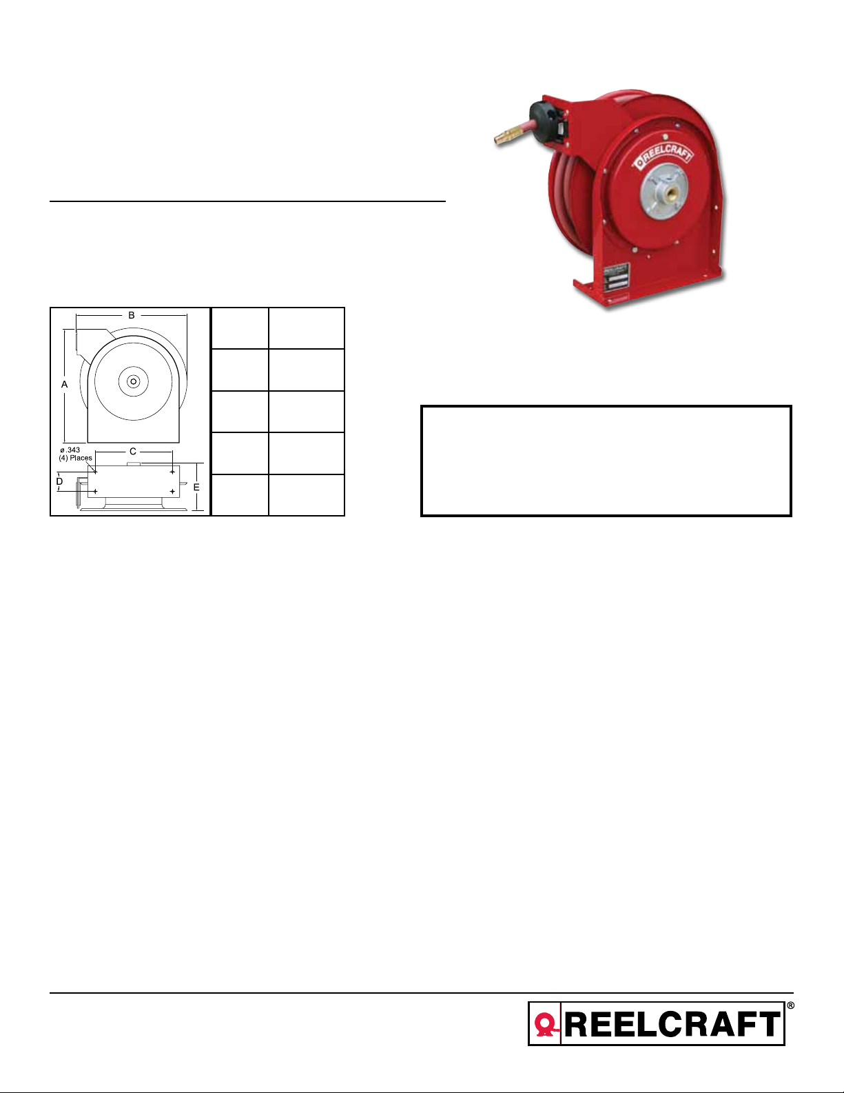
Series 5000 Spring Driven Hose Reels
Low and Medium Pressure Model Numbers:
A5800 OLP A5800 OMP
A5825 OLP A5825 OMP
Dimensions
A 14 3/8”
B 14”
C 9 3/4”
SAFETY
INSTALLATION:
MOUNTING:
LUBRICATION:
REPLACING HOSE:
D 2 1/2”
E 6 1/8”
A flexible hose connection must be used between the hose reel inlet and the source of supply to prevent possible
misalignment and binding.
The hose reel is equipped with a universal mounting bracket so that it can be mounted on the floor, wall or
ceiling; whichever place is convenient. The hose guide arm can be moved to the position desired by removing
the screws fastening the guide bracket to the reel base. Shift the guide arm bracket so the hose comes off the
reel at the desired position and replace the screws. NOTE: For proper installation in wall mount applications, ensure
reel is mounted with inlet on the right as you are facing the reel. Failing to do so could cause latching issues.
Hose reel spring and bearings are factory lubricated and require no further lubrication.
1. Wind spool flange clockwise-facing swivel-until spring is tight.
2. Back off three turns and latch.
3. Insert hose through roller guide.
4. Connect hose fitting to swivel joint and secure hose with clamps.
1. Do not use reel at higher pressures or temperatures than listed on
the back of this bulletin.
2. Remove all spring tension before beginning dissassembly process.
ADJUSTMENTS:
REPAIRS:
Reelcraft Industries, Inc. • 2842 E Business Hwy 30, Columbia City, IN 46725
Ph: 800-444-3134 / 260-248-8188 • Fax: 800-444-4587 / 260-248-2605
Customer Service: 855-634-9109 • reelcraft@reelcraft.com • www.reelcraft.com
To adjust spring tension, add or remove wraps of hose from the spool, one wrap at a time until desired tension is
obtained.
Extensive repairs should be performed only by an authorized serviceman or factory to avoid damage which may
void your warranty. Remove all spring tension before beginning disassembly process.
Form# 1170-505 Rev: 4/2013
Page 2
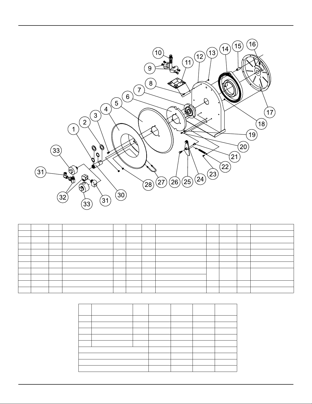
Series 5000 Spring Driven Hose Reels
Item # Part # # Req. Description Item # Part # # Req. Description Item # Part # # Req. Description
1 300031 2 1” Snap Ring 13 S300011 7 Hex Lock Nut 23 300001 5 10-32 x 3/8” Screw
2 300034 2 Spacing Washer 14 S505740 1 Drive Spring Assembly 24 400020 1 O-ring
3 S295-102 3 1/4-10 Hex Head Screw 15 S261360 1 Spring Case Stud 25 S400109 1 Latch Plate Assembly
4 260022 1 Flange Sheave 16 300006 1 3/8-16 x 1/2” Set Screw 26 300035 1 10-32 x 1” Mach. Screw
5 500006 1 Sheave Disk 17 S500103 1 Spring Case & Hub Assembly 27 3-117440 1 U-bolt Hose Clamp
6 S500019 1 Latch Cam 18 S82-15 1 10-32 x 3/8” Nyloc Nut 28 261650-1 2 1/4-20 Zinc Nyloc Nut
7 S260648 1 Spring Arbor 19 S400021 1 Latch Bumper
8 300002 2 10-32 x 1/2” Mach. Screw 20 S32-136 1 10-24 x 3/8” Self Tap Screw
11 S500107 1 Guide Arm & Roller Assembly 21 S400012 1 Latch Bushing
12 500101 1 Base Assembly 22 S400018 1 Latch Spring
Item # Description # Req.
9 Hose Bumper Assembly 1 None 2-HR1004-3 None 2-HR1004-3
10 Hose Assembly 1 None 601020-25 None 21-260043
31 Swivel Union 1 300010 300010 260749 260749
32 Swivel Union 1 300010 300010 S257-26 S257-26
33 Swivel Assembly 1 S600887-1 S600887-1 S600595-1 S600595-1
Hose I.D. and Length None 1/4” x 20’ 1/4” x 25’ 1/4” x 30’
Reel Inlet Connection 3/8” F.P.T. 3/8” F.P.T. 3/8” F.P.T. 3/8” F.P.T.
Max. Operating Pressure 500 P.S.I. 300 P.S.I. 3250 P.S.I. 3250 P.S.I.
Max. Operating Temperature 210° F 150° F 210° F 210° F
Model
A5800 OLP
Model
A5825 OLP
A5800 OMP
30 602305 1
Model
Model
A5825 OMP
Main Shaft & Snap Ring
Assembly
Page 2
www.reelcraft.com
Page 3

Instrucciones de Operacion
Series 5000 Carreteles para Mangueras
Números de modelo bajos y medios de la presión:
A5800 OLP A5800 OMP
A5825 OLP A5825 OMP
Dimensiones
A 14 3/8”
B 14”
C 9 3/4”
SEGURIDAD
INSTALACION:
MONTAJE:
LUBRICACION:
REMPLAZO DE LA
MANGUERA:
D 2 1/2”
E 6 1/8”
Una manguera flexible de coneccion tiene que ser usada entre la entrada de la manguera de el carretel y la fuente
de abastecimiento para prevenir un posible desalineamiento y enlazamiento.
El riel de manguera esta equipado con un soporte de montaje universal para que esta pueda ser montada en el
piso, pared o techo; cualquier sitio es conveniente. El brazo guia de la manguera puede ser movido a la posicion
deseada removiendo los tornillos firmemente de la guia de soporte de la base de el carretel. Posicione la guia de
soporte del brazo abra que la manguera quede afuera del carretel a la posicion deseada; y reemplaze los tornillos.
NOTA: Para la instalación apropiada en usos del montaje de la pared, asegúrese que el carrete esté montado con
la entrada a la derecha mientras que usted está haciendo frente al carrete. El no poder hacer tan podía causar el
enganche de ediciones.
El resorte del carretel de la manguera y el cojinete estan empacado con grasa y no requiere futura lubricacion.
1. De vueltas a la palanca giratoria hacia la derecha hasta que el resorte este apretado.
2. Devuelva 3 giros y asegure.
3. Inserte la manguera atravez de la guia del rodillo.
4. Conecte y encaje la manguera a la salida hembra de el codo de tuberia.
1. No use carreteles a presiones o temperaturas altas que no se
mencionan en este boletin.
2. Remueva la tension antes de empezar el proceso de desarme.
AJUSTAMIENTO:
REPARACION:
Page 3
Reelcraft Industries, Inc. • 2842 E Business Hwy 30, Columbia City, IN 46725
Ph: 800-444-3134 / 260-248-8188 • Fax: 800-444-4587 / 260-248-2605
Customer Service: 855-634-9109 • reelcraft@reelcraft.com • www.reelcraft.com
Para ajustar la tension del resorte en el carretel, agrege o quite vueltas hasta que la tension deseada es obtenidad.
Extensivas reparaciones deberan ser realizadas por una persona de servicio autorizada o por la fabrica para evitar
daños que eliminen su garantia. Remueva todos los resortes de tension antes del proceso de desmontaje.
Form# 1170-505 Rev: 4/2013
Page 4

Series 5000 Carreteles para Mangueras
Arti
culo
1 300031 2 Anillo Rápido Del 1” 13 S300011 7
Part #
No.
Req.
Descripcion
Arti
culo
Part #
No.
Req.
Descripcion
Tuerca de fijación De la Tuerca
hexagonal
Arti
culo
Part #
No.
Req.
Descripcion
23 300031 5 tornillo 10-32 del x 3/8”
2 300034 2 Arandela Del Espaciamiento 14 S505740 1 Conduzca El Resorte Ass’y 24 400020 1 O’Ring
3 S295-102 3
4 260022 1
1/4-10 Tornillo Principal De Tuerca
hexagonal
Reborde De la Polea canalada
15 S261360 1
16 300006 1 tornillo de presión 3/8-16 x 1/2” 26 300035 1
5 500006 1 Disco De la Polea canalada. 17 S500103 1 Caso Y Cubo Ass’y Del Resorte 27 3-117440 1
Perno prisionero Del Caso Del Resorte
25 S400109 1 Placa De Cierre Ass’y
tornillo de la máquina 10-32 del x 1”
Abrazadera De Manguera Del U-Perno
6 S500019 1 Leva Del Cierre 18 S82-15 1 Caso Y Cubo Ass’y Del Resorte 28 261650-1 2 1/4-20 Tuerca De Nyloc Del Cinc
7 S260648 1 Cenador Del Resorte 19 S400021 1 Tope Del Cierre 30 602305 1 Eje Principal
8 300002 2
11 S500107 1
tornillo de la máquina 10-32 del x 1/2”
Brazo Y Rodillo Ass’y De la Guía
20 S32-136 1
21 S400012 1 Buje Del Cierre
tornillo que golpea ligeramente 10-24 del
x 3/8”
12 500101 1 Assembly Bajo 22 S400018 1 Resorte De Cierre
ARTÍCULO DESCRIPCIÓN
NO.
A5800 OLP A5825 OLP A5800 OMP A5825 OMP
REQ.
9 Tope de la manguera ass’y 1 ningunos 2-HR1004-3 ningunos 2-HR1004-3
10 Manguera ass’y 1 ningunos 601020-25 ningunos 21-260043
31 Unión Del Eslabón giratorio 1 300010 300010 260749 260749
32 Unión Del Eslabón giratorio 1 300010 300010 S257-26 S257-26
33 Eslabón giratorio ass’y 1 600915 600915 602032-1 602032-1
Identificación De la Manguera Y Longitud ningunos 1/4” x 20’ 1/4” x 30’ 1/4” x 35’
Conexión De la Entrada Del Carrete 3/8” F.P.T. 3/8” F.P.T. 3/8” F.P.T. 3/8” F.P.T.
Presión De Funcionamiento Máxima 3000 P.S.I. 2750 P.S.I. 2750 P.S.I. 2750 P.S.I.
Temperatura De Funcionamiento Máximo 210°F 210°F 210°F 210°F
Page 4
www.reelcraft.com
Page 5

Instructions D’Opération
Série 5000 Enrouleurs de Tuyau Manuels
Bas et moyens numéros de type de pression:
A5800 OLP A5800 OMP
A5825 OLP A5825 OMP
Dimensiones
A 14 3/8”
B 14”
INSTALLATION:
MONTAGE:
LUBRIFICATION:
REMPLACEMENT
DE TUYAU:
C 9 3/4”
1. N’utillisez pas les enrouleurs à pression plus haut ou aux
D 2 1/2”
E 6 1/8”
Un raccord de tuyau flexible doit être utilisé entre l’entrée d’enrouleur et la source d’alimentation pour prévenir le
défaut d’alignment ou le coincement.
L’enrouleur de tuyau est équipé d’un support de montage universal pour être monté au plancher, au mur, ou au
plafond, quel que soit la position que vous désiriez. Le guide de tuyau peut être mis au position désiré en enlevant
les vis attachant le support guide au base de l’enrouleur. Positionez le support guide pour que le tuyau puis
enrouler de l’enrouleur comme désiré et remplacez les vis. NOTE : Pour l’installation appropriée dans des applications de bâti de mur, assurez que l’enrouleur est montée avec l’admission du côté droit pendant que vous faites
face à l’enrouleur. Ne pas faire ainsi a pu causer verrouiller des issues.
Le ressort de l’enrouleur et les pailers sont lubrifiés à vie en usine.
1. Enroulez la piéce d’espacement bridée dans le sens des aiguilles d’une montre (face au pivot) jusqu’ au ressort
est bien serré.
2. Faites marche arriére 3 tours, et puis fermez au loquet le mécanisme.
3. Insérez le tuyau à travers le guide et le trou de la pièce d’espacement bridée.
4. Connectez le raccord de tuyau au joint de pivot, et fixez le tuyau avec des crampons.
températures plus hauts que ce qui est noté sur le dos de ce
bulletin.
2. Enlevez toute tension du ressort avant de désassembler.
LA SÉCURITÉ
RÉGLAGES:
RÉPARATIONS:
Page 5
Reelcraft Industries, Inc. • 2842 E Business Hwy 30, Columbia City, IN 46725
Ph: 800-444-3134 / 260-248-8188 • Fax: 800-444-4587 / 260-248-2605
Customer Service: 855-634-9109 • reelcraft@reelcraft.com • www.reelcraft.com
Pour régler la tension du ressort, ajoutez ou enlevez des tours de câble, un tour à la fois, jusqu’à l’obtention de la
tension désirée.
Des réparations étendues doivent être fait uniquement par un homme de service authorisé ou par l’usine pour éviter
le dommage quie peut annuler votre garantie. Enlevez toute tension de ressort avant de désassembler.
Form# 1170-505 Rev: 4/2013
Page 6

Série 5000 Enrouleurs de Tuyau Manuels
N°
d’article
N° de
piéceN°requis
1 300031 2 Anneau ressort De 1” 13 S300011 7 Contre-écrou De Sortilège 23 300031 5 vis 10-32 x de 3/8”
2 300034 2 Rondelle D’Espacement 14 S505740 1 Conduisez Le Ressort Ass’y 24 400020 1 O-ring
3 S295-102 3 1/4-10 Vis à tête hex 15 S261360 1 Goujon De Cas De Ressort 25 S400109 1 Plat De Verrou Ass’y
4 260022 1 Bride De Poulie 16 300006 1 vis de réglage 3/8-16 x 1/2” 26 300035 1 vis de machine 10-32 x de 1”
5 500006 1 Disque De Poulie. 17 S500103 1 Cas Et Moyeu Ass’y De Ressort 27 3-117440 1
6 S500019 1 Came De Verrou 18 S82-15 1 Cas Et Moyeu Ass’y De Ressort 28 261650-1 2 1/4-20 Écrou De Nyloc De Zinc
7 S260648 1 Axe De Ressort 19 S400021 1 Butoir De Verrou 30 602305 1 Axe Principal
8 300002 2 vis de machine 10-32 x de 1/2” 20 S32-136 1 vis de tapement 10-24 x de 3/8”
11 S500107 1 Bras Et Rouleau Ass’y De Guide 21 S400012 1 Douille De Verrou
12 500101 1 Assembly Bas 22 S400018 1 Ressort De Verrou
Description
N°
d’article
9 Butoir de tuyau ass’y 1 aucune 2-HR1004-3 aucune 2-HR1004-3
10 Tuyau ass’y 1 aucune 601020-25 aucune 21-260043
31 Union De Pivot 1 300010 300010 260749 260749
32 Union De Pivot 1 300010 300010 S257-26 S257-26
33 Pivot ass’y 1 600915 600915 602032-1 602032-1
Identification De Tuyau Et Longueur aucune 1/4” x 20’ 1/4” x 30’ 1/4” x 35’
Raccordement D’Admission De Bobine 3/8” F.P.T. 3/8” F.P.T. 3/8” F.P.T. 3/8” F.P.T.
Pression de fonctionnement Maximum 3000 P.S.I. 2750 P.S.I. 2750 P.S.I. 2750 P.S.I.
Température de fonctionnement Maximum 210°F 210°F 210°F 210°F
Description
N°
d’article
N° de
piéceN°requis
N°
requis
A5800 OLP A5825 OLP A5800 OMP A5825 OMP
Description
N°
d’article
N° de
piéceN°requis
Description
Collier De la Conduite D’U-Boulon
Page 6
www.reelcraft.com
 Loading...