

Page 1
3100 SERIES
Hose Reel Operations Manual
IMPORTANT
Read this manual carefully before installing,
operating or servicing this equipment.
PERSONAL SAFETY
Personal injury and/or equipment damage may result
if proper safety precautions are not observed.
WARNING: Even low pressure can cause irreparable damage or death.
Exercise extreme caution while operating or servicing this equipment.
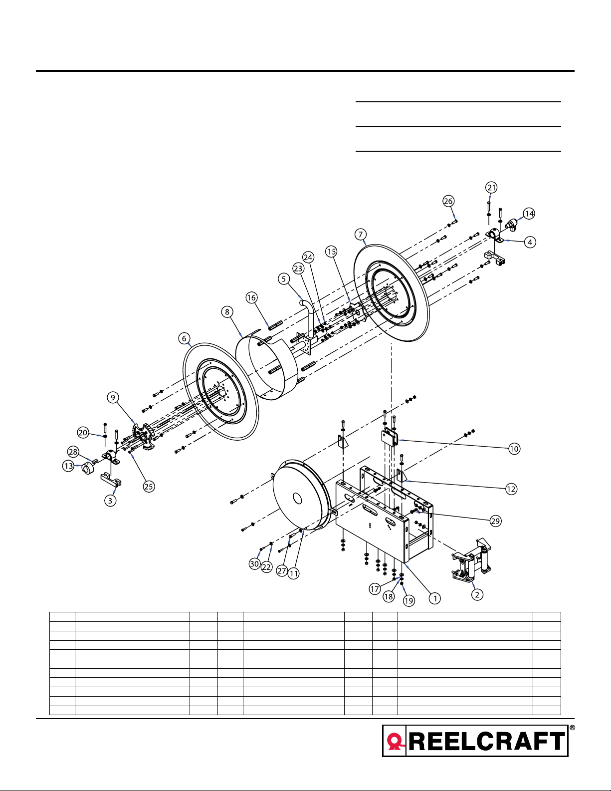
To order replacement parts pleas provide the
following information:
∙ Model number
∙ Serial number
∙ Part description and/or balloon number listed
below. *Some parts may not be shown, in this
case a detailed part description will be required.
ORDER #:
MODEL #:
SERIAL #:
Item # Title Quantity Item # Title Quantity Item # Title Quantity
1 FRAME WELDMENT ASSY 1 11 SPRING CASE ASSY 1 21 S347-69 HEX CAP SCREW 3/8”-16 UNC X 2” 4
2 GUIDE ASSY BOX 1 12 327279 MOUNTING BRACKET 2 22 S350-4 WASHER 1/4” 12
3 PAT888AL CASTING BEARING SPACER 2 13 390171 ARBOR SPRING 1 23 S339-516 LOCK WASHER 5/16” 6
4 310212 BEARING 1.312” ID 2 14 SWIVEL 1 24 S338-4 HEX NUT 1/4”-20 9
5 FLUID PATH 1 15 HEAD INSERT 1 25 S347-47 HEX CAP SCREW 1/4-20 X 1.5” 6
6 HEAD DRIVE SIDE 1 16 TIE ROD 6 26 S347-65 HEX CAP SCREW 3/8”-16 UNC X 1” 16
7 HEAD FLUID PATH SIDE 1 17 S350-6 WASHER 3/8” 16 27 S347-66 HEX CAP SCREW 3/8”-16 UNC X 1.25” 6
8 DRUM 1 18 S339-616 LOCK WASHER 3/8” 30 28 261275 KEY ARBOR 1
9 327258 RATCHET 1 19 S338-6 HEX NUT 3/8”-16 UNC 18 29 S339-416 LOCK WASHER 1/4” 3
10 S360100 PAWL BRACKET ASSY 1 20 S350-41 WASHER SMALL 3/8” 16 30 S347-45 HEX CAP SCREW 1/4”-20 X 1” 3
Reelcraft Industries, Inc. • 2842 E Business Hwy 30, Columbia City, IN 46725
Ph: 800-444-3134 / 260-248-8188 • Fax: 800-444-4587 / 260-248-2605
Customer Service: 855-634-9109 • reelcraft@reelcraft.com • www.reelcraft.com
Page 2
Hose Reel Operations Manual
PERSONAL SAFETY
• Ensure that reel is properly installed before connecting supply line (see instructions).
• Before connecting supply line to reel, ensure that supply line prssure does not exceed maximum rated working pressure of the
reel.
• Do not wear loose fi tting clothing while operating reel.
• Be aware of other personnel / machinery in work area.
• If a leak occurs in hose or reel, remove supply line pressure immediately.
• Treat and respect a hose reel as any other piece of machinery, observing all common safety practices.
WARNINGS & TIPS
Prevent static sparking
• Pull hose by grasping the hose itself not by the control valve swivel.
• When working around flammable liquids such as solvents, paints, chemicals or petroleum products, ensure that the hose reel
and the equipment being serviced is properly grounded. Use a grounding hose (static wire).
• Use an ohmmeter to check continuity of the grounding circuit. Fire and/or explosion can result if proper grounding is not
achieved.
• If reel ceases to unwind or rewind properly, remove power immediately. Do not pull or jerk on hose. Find and remedy problem
before continuing.
PRE-INSPECTION
1. Check reel for shipping damages.
2. Insured all parts are supplied as ordered.
3. Record Model Number and Serial Number for future reference.
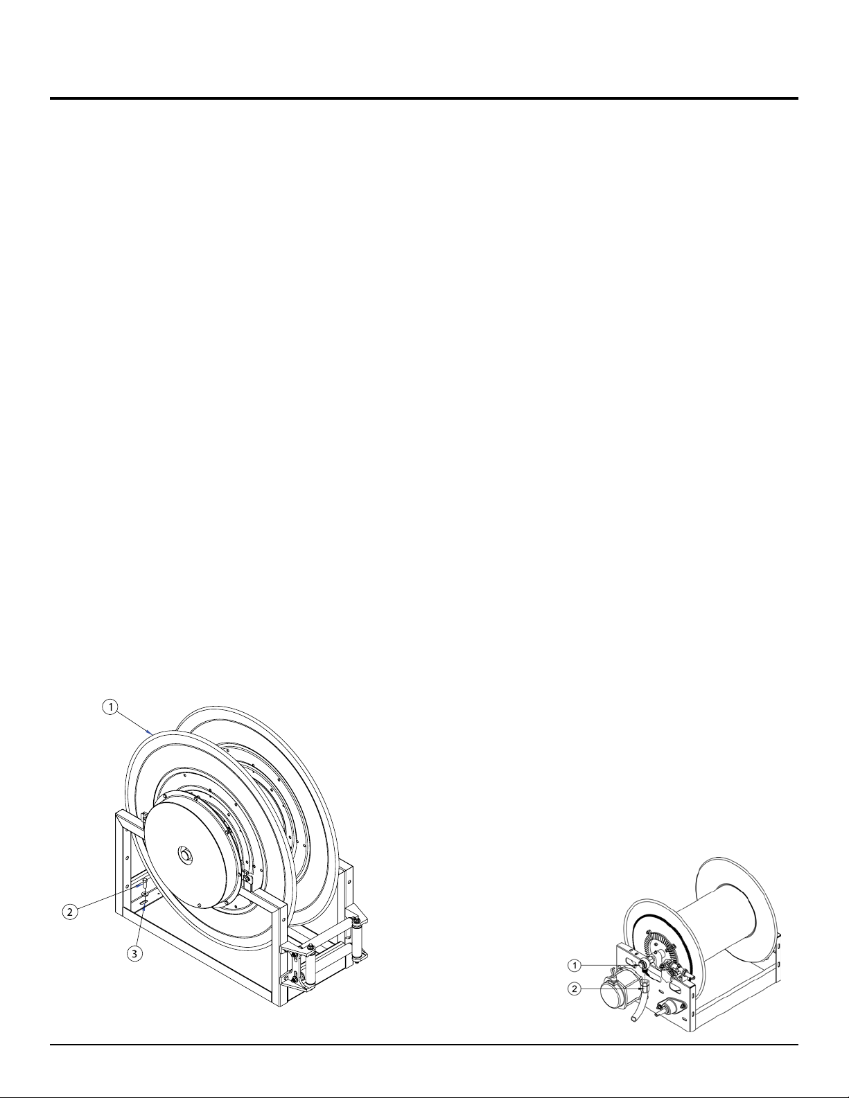
MOUNTING
1. Unpack and inspect reel - rotating spool (1) to check for
smooth operation.
2. Ensure that mounting surface is rigid and flat to prevent
binding of reel after it is installed. This is important to ensure proper alignment.
3. Drill four mounting holes in reel frame. Secure reel to
mounting surface by inserting four bolts (2) through the
four mounting holes (3) just drilled into the reel frame.
Tighten securely to ensure a solid, rigid attachment.
INSTALL / REPLACE THE HOSE
CAUTION: Exercise extreme caution when adding or remov-
ing spring tension. Ensure reel base is fastened down prior to
adjusting tension. Do not move spool while tightening hose or
latch will disengage. Do not let go of the hose until latch mechanism is engaged.
1. To achieve proper tension, wind spool flange required
number of turns (refer to online tech bulletin). Do not overtighten.
2. Engage hose latching mechanism.
3. Insert hose through roller guide.
4. Connect hose fitting to female outlet. Install hose bumper
stop at desired position.
INLET CONNECTION
NOTE: Install a union fitting as near as possible to the swivel
joint inlet, so the joint can be easily removed for servicing.
CONNECTING THE SUPPLY LINE FOR THREADED INLET
SWIVELS
NOTE: Avoid strain on swing joint at all swivel inlets must be
connected to the fluid supply by using a flexible connector.
1. Apply thread compound to the swivel (1) and connecting
hose fitting (2) threads.
2. Thread connecting hose fitting (2) into swivel (1). Tighten
securely.
3. With control valve open, fully extend and charge hose to
purge system of
gases. When fluid
appears at control
valve, close valve,
clos valve. This
prevents flattening
of hose and excessive pressure on
drum when fluid
supply is reinitialized at a later time.
Page 2
www.reelcraft.com
Page 3

Hose Reel Operations Manual
VICTAULIC INLET SWIVELS
NOTE: Victaulic - Type swivel joint inlet connections must be
carefully aligned. Two victaulic connections, correctly installed,
allow adequate flexibility for smooth rotation.
1. Connect victaulic coupling onto inlet swivel fitting and inlet
supply line.
2. Adjust inlet supply line to verify flexibility exists for proper
alignment.
3. With control valve open, fully extend and charge hose
to purge system of gases. When fluid appears at control
valve, close valve. This prevents flattening of hose and excessive presure on drum when fluid supply is reinitialized
at a later time.
Victaulic
Connection
Flexible
Connection
REPLACING THE SPRING CASE
Ensure reel base is fastened down before attempting to replace the spring case.
CAUTION: Remove all spring tension before replacing the
spring case! DO NOT ATTEMPT TO OPEN SPRING CASE!
Serious injury may occur.
1. Loosen and remove hardware (1) securing spring case (2)
to frame.
2. Slide horizontally off frame and shaft (5).
3. Leave spring arbor (3) and key (4) on shaft (5).
4. Safely discard old spring case and install new spring case.
5. Install fasteners.
6. Tension reel acccordingly (see Install / Replace Hose).
NOTE: Failure to use flexible connector with any live reel will
void warranty.
For larger reels, gooseneck may be removed from reel to fit to
hose. Note that if the reel has a welded or threaded riser in the
fluid path assembly, it cannot be removed to attach the hose.
CAUTION: Do not connect the output hose to the gooseneck
(1) until after the reel is installed and motor connections are
complete. Fill the hose before winding on the reel to prevent
excessive pressure on the
drum when hose is filled.
1. Apply thread compound
to connecting gooseneck
(1) and output hose fitting
threads (2).
2. Hand thread output hose
fitting (2) into gooseneck
(1).
3. Using a wrench, firmly
hold gooseneck (1) while
tightening out put hose fitting (2).
REPLACING THE SWIVEL
CAUTION: Remove supply line pressure before performing the
following procedures.
1. Remove supply line
(2) from the swivel
(1) or inlet.
2. Remove swivel (1)
from inlet shaft (3).
3. Install replacement
swivel by reversing
steps 1 & 2.
REPLACING “U” CUP SEALS ON NORDIC SWIVELS
1. Remove supply line (3) from inlet adaptor (1).
2. Remove all three bolts (2).
3. Pull seal from recess inside of
inlet adaptor.
4. Examine new seal (5) and ring
(4) to check for damage.
5. Moisten face of seal with lubricant and replace into inlet
adaptor (1).
6. Bolt adaptor back in place and
re-install supply line.
www.reelcraft.com
Page 3
 Loading...