

Page 1
Pantone 534 Blue
Pantone 123 Yellow
Pantone 485 Red
Pantone 123 Yellow
Pantone 534 Blue
Black
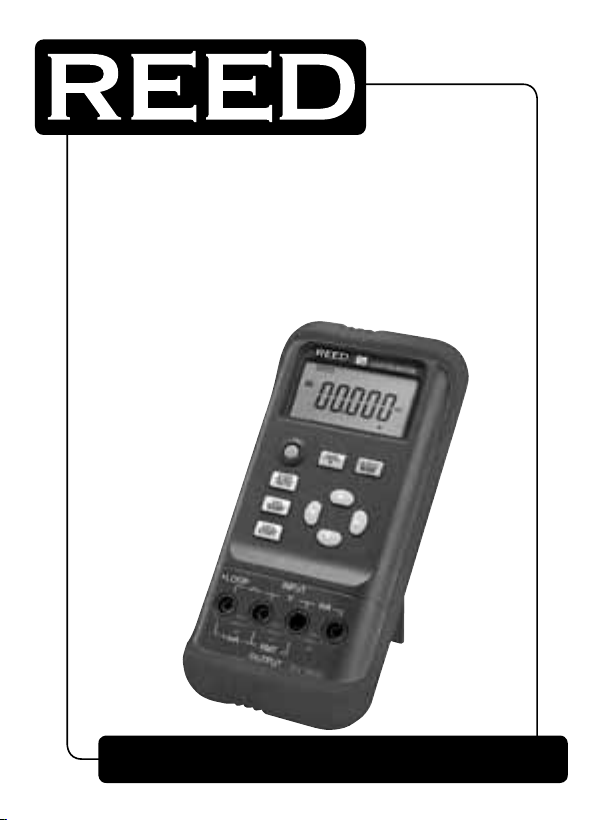
Model
VC05
Loop Calibrator
Instruction
Manual
www
reedinstruments
REED-Direct.ca
com
1.800.868.7495[email protected]
Page 2

Pantone 534 Blue
Pantone 123 Yellow
Pantone 485 Red
Pantone 123 Yellow
Pantone 534 Blue
Black
Rich Black -
20/20/20/100
Blue - 100/80/30/5
Yellow - 0/27/100/0
Red - 10/100/100/5
Yellow - 0/27/100/0
Blue - 100/80/30/5
Table of Contents
Safety ...........................................................................................................
Features ........................................................................................................
Specications ...............................................................................................
Instrument Description .................................................................................
Operating Instructions ..................................................................................
ON/OFF .....................................................................................................
Outputs .....................................................................................................
Automatic Power Off .................................................................................
Calibration .................................................................................................
Battery Replacement ....................................................................................
For service (repairs or calibration) on this or any other REED product
or information on other REED products, contact REED Instruments at
[email protected].
www
REED-Direct.ca
reedinstruments
com
1.800.868.7495[email protected]
2
Page 3
Pantone 534 Blue
Pantone 123 Yellow
Pantone 485 Red
Pantone 123 Yellow
Pantone 534 Blue
Black
Rich Black -
20/20/20/100
Blue - 100/80/30/5
Yellow - 0/27/100/0
Red - 10/100/100/5
Yellow - 0/27/100/0
Blue - 100/80/30/5
Safety Information
To ensure safe usage, the following signs are used only as specied in this
instruction manual.
WARNING
correct instruction, therefore causing potential hazards to the user or
instrument. This also indicates how to avoid such hazards.
! CAUTION
correct instructions, therefore causing potential hazards to the instrument.
Also indicates how to avoid incorrect operation.
NOTE
the correct operation before proceeding.
To prevent the user and the instrument from electric shock and other
hazards, it is necessary to follow the following regulations:
Warning -
• Do not operate the instrument in the presence of ammable gas, explosive gas or vapor. This is extremely dangerous.
• Never apply more than 30V between any two terminals, or between
terminal and ground.
Caution -
• The split case (top and bottom) is not to be removed, unless by
qualied technicians.
• To clean the instrument, periodically wipe the case with a damp
cloth and mild detergent, do not use any corrosive solvents.
Note -
• For optimal accuracy, allow the instrument to warm up for 5
minutes before operating.
•
If the automatic reference-junction temperature compensation of the
instrument deviates from its designed accuracy, on this or any other REED
product, contact REED Instruments at [email protected].
Indicates that the current operation does not comply with
Indicates that the current operation does not comply with
Serves as a sign to remind the user that they must understand
WARNING
! CAUTION
NOTE
www
REED-Direct.ca
reedinstruments
com
1.800.868.7495[email protected]
3
Page 4
Pantone 534 Blue
Pantone 123 Yellow
Pantone 485 Red
Pantone 123 Yellow
Pantone 534 Blue
Black
Rich Black -
20/20/20/100
Blue - 100/80/30/5
Yellow - 0/27/100/0
Red - 10/100/100/5
Yellow - 0/27/100/0
Blue - 100/80/30/5
Features
• mA sourcing, simulation and measurement
• 0-28 VDC measurement to check loop voltage
• 0.02% accuracy and 0.001% of span display
• Simulate mA and % of span display
• Selectable step or ramp outputs
• 24V loop power supply
Specifications
Power supply: 9V battery (ANSI/NEDA 1604A or IEC 6LR619V alkaline)
Battery life: About 20 hours under the condition of 10mA
Size: 200×100×40mm (with holster)
Weight: 550g (with holster)
Includes: Set of CF-36 industrial test leads (alligator clips
attached to probes), protective holster, carrying case,
and battery
Output Functions
Applicable range from 18 to 28°C, within one year of calibration.
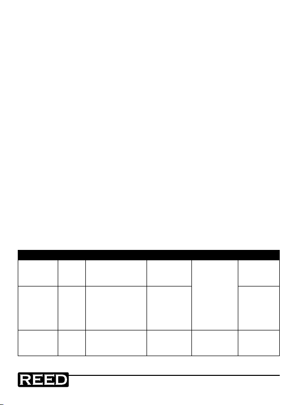
Output Range Output Range Resolution Accuracy Note
Current 20mA 0.000 to 22.000mA 0.001mA
Simu.
transmitter
(absorp.
current)
Loop power 24V - - ±10%
-20mA
0.000 to
–22.000mA
www
reedinstruments
REED-Direct.ca
0.001mA
±0.05% of set
value ±4A
Max 1K at
20mA, see
Note 1
Max 1K at
20mA, see
Note 2
Max output
current up to
25mA
com
1.800.868.7495[email protected]
4
Page 5
Pantone 534 Blue
Pantone 123 Yellow
Pantone 485 Red
Pantone 123 Yellow
Pantone 534 Blue
Black
Rich Black -
20/20/20/100
Blue - 100/80/30/5
Yellow - 0/27/100/0
Red - 10/100/100/5
Yellow - 0/27/100/0
Blue - 100/80/30/5
Input Functions
Applicable range from 18 to 28°C, within one year of calibration.
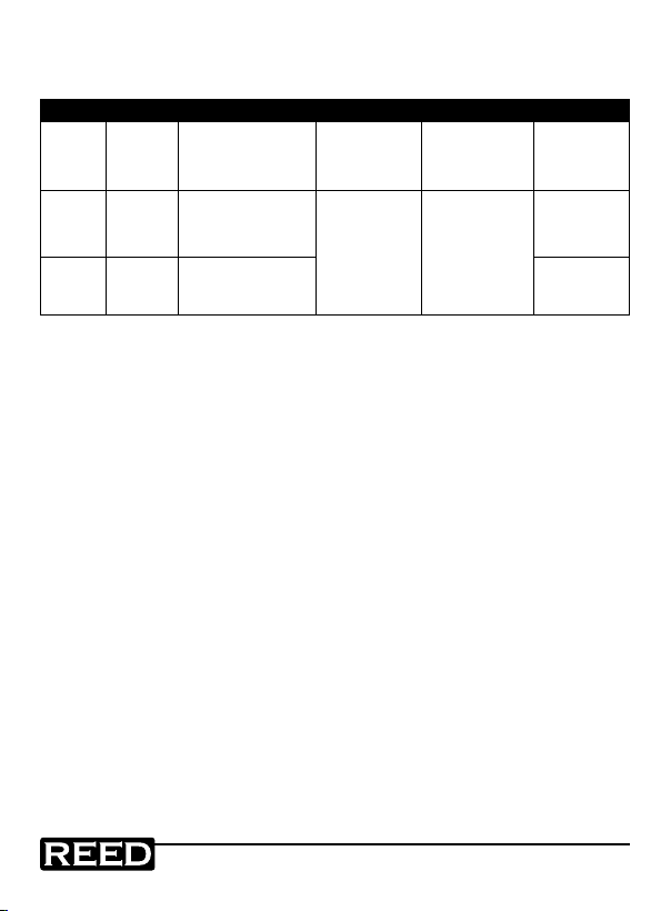
Input Range Input Range Resolution Accuracy Note
Voltage 28V -0.200 to 28.000V 1mV
±0.02% of
reading ±2mV
Current 20mA -1.000 to 22.000mA
±0.02% of
reading ±4A
Loop
power
0.001mA
20mA 0.000 to 22.000mA
Note 1: When the battery voltage exceeds 6.8V, the max. load is 1K at
20mA. When its voltage lies between 5.8V and 6.8V, the max
load is 700 at 20mA.
Note 2: Power supply range: 5 to 25VDC.
Note 3: Temperature coefcient: ±0.005% of the range per °C for the
temperature ranges 5°C to 18°C and 28°C to 40°C.
Input
resistance
2M
Max 1K at
20mA, see
Note 2
Providing
24V loop
power
For service on this or any other REED product or information on other
REED products, contact REED Instruments at [email protected]
www
REED-Direct.ca
reedinstruments
com
1.800.868.7495[email protected]
5
Page 6
Pantone 534 Blue
Pantone 123 Yellow
Pantone 485 Red
Pantone 123 Yellow
Pantone 534 Blue
Black
Rich Black -
20/20/20/100
Blue - 100/80/30/5
Yellow - 0/27/100/0
Red - 10/100/100/5
Yellow - 0/27/100/0
Blue - 100/80/30/5
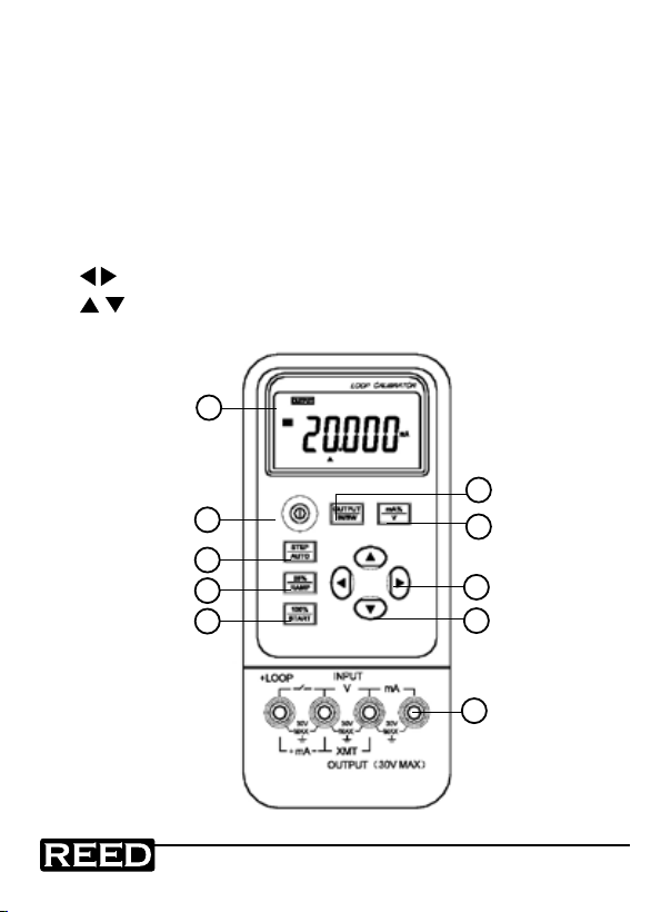
Instrument Description
1. LCD screen
2. Power button
3. Single step/auto switch button
4. 25% single step setting/auto ramp button
5. 0% & 100% of setting/auto ramp start button
6. Output/input on-off button
7. Unit mA%/V select button
8. output digit selection button
9. output value setting button
10. Input/output terminals
1
2
3
4
5
www
REED-Direct.ca
reedinstruments
7
8
9
10
com
6
1.800.868.7495[email protected]
Page 7
Pantone 534 Blue
Pantone 123 Yellow
Pantone 485 Red
Pantone 123 Yellow
Pantone 534 Blue
Black
Rich Black -
20/20/20/100
Blue - 100/80/30/5
Yellow - 0/27/100/0
Red - 10/100/100/5
Yellow - 0/27/100/0
Blue - 100/80/30/5
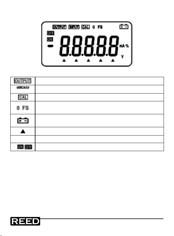
Display Description
Indicates that the instrument is in an output state
Indicates that the instrument is in a input state
Indicates that the instrument is in a calibration state
Indicates that the instrument is in a calibration state, denoting
that the zero point or the full scale point is now in calibration
Indicates that the battery power is low and needs to be
replaced
Indicates that the output digits need to be set
V. mA. % Indicates the current output value (unit of measure)
Indicates that the output signal is on or off
Operating Instructions
Power ON/OFF
Press the Power button to turn the instrument on. Press this button again,
holding for one second to turn the instrument off. When the instrument is
on, it will begin an internal self-diagnosis at which time the full screen will
be displayed. Once complete, the instrument is ready to be used.
www
REED-Direct.ca
reedinstruments
com
1.800.868.7495[email protected]
7
Page 8
Pantone 534 Blue
Pantone 123 Yellow
Pantone 485 Red
Pantone 123 Yellow
Pantone 534 Blue
Black
Rich Black -
20/20/20/100
Blue - 100/80/30/5
Yellow - 0/27/100/0
Red - 10/100/100/5
Yellow - 0/27/100/0
Blue - 100/80/30/5
Automatic power-off
As a default the instrument will be set to automatically turn itself off after
10 minutes without any action. Follow the steps below to turn the AutoPower Off function off.
1. Be sure the meter is powered off.
2. Press both the POWER and mA%/V buttons simultaneously. The
display will indicate the symbol ‘AP-XX’.
3. Press the button to activate or deactivate the Auto-Power Off
function. ‘AP-OF’ indicates that there is no automatic power-off
function set, and ‘AP-ON’ indicates the automatic power-off function is activated.
4. Turn the meter off to save the setting.
Outputs
The output terminal of the instrument can produce DC voltages set by the
user or simulating resistance.
! CAUTION
operation. If any improper voltage is applied to the output terminal, it will
cause damage to the internal circuits.
Output Operation Procedure
Function
Operation
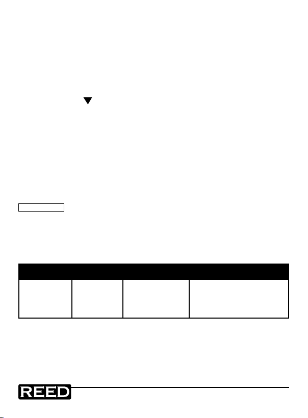
DCA 20 mA 20 mA or %
Do not apply any voltage to the output terminal during the
Range
Operation
Display Set Range
00.000 mA
00.000 to 22.000 mA
or
-025.00 mA %
-025.00 to 112.50 mA %
or
www
REED-Direct.ca
reedinstruments
com
8
1.800.868.7495[email protected]
Page 9
Pantone 534 Blue
Pantone 123 Yellow
Pantone 485 Red
Pantone 123 Yellow
Pantone 534 Blue
Black
Rich Black -
20/20/20/100
Blue - 100/80/30/5
Yellow - 0/27/100/0
Red - 10/100/100/5
Yellow - 0/27/100/0
Blue - 100/80/30/5
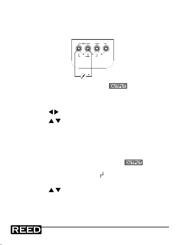
Current Output
+
+LOOP
30V MAX
OUTPUT
+
mA
XMT
30V
MAX
mA
30V
MAX
30V
MAX
V
INPUT
1. Insert one end of the test leads into the +mA output jack and
connect the other end to the input of the meter, as shown in the
diagram below.
2. Press the OUTPUT/IN/SW button and
will
display indicating that the calibrator is in an output state.
3. Press the mA%/V button to select the output to be either mA or
%, in which 0% indicates 4mA and 100% indicates 20mA.
4. Press the
buttons to select the output digits.
5. Press the button to change the numerical value of the set
digits. Hold the button and the value will keep varying.
25% Step Current Output
1. Connect the test leads to the meter as stated in the Current
Output procedures.
2. When the OUTPUT/IN/SW button is pressed,
in the display it indicating the calibrator is in an output state.
3. Press the 25%/RAMP button and
4. Press the mA%/V button to select the set output to mA or %
5. Press the button to change the output in a value of 25%,
in which 0% indicates 4mA and 100% indicates 20mA.
6. Press the 25%/RAMP button again to exit.
www
reedinstruments
REED-Direct.ca
will appear on the LCD.
com
appear on the
will appear
1.800.868.7495[email protected]
9
Page 10
Pantone 534 Blue
Pantone 123 Yellow
Pantone 485 Red
Pantone 123 Yellow
Pantone 534 Blue
Black
Rich Black -
20/20/20/100
Blue - 100/80/30/5
Yellow - 0/27/100/0
Red - 10/100/100/5
Yellow - 0/27/100/0
Blue - 100/80/30/5
Current Output Set for Zero Point & Full Scale
1. Connect the test leads to the meter as stated in the Current Output procedures.
2. Press the OUTPUT/IN/SW button and
will appear on the
display indicating that the calibrator is in an output state.
3. Press the 100%/START button and the symbols ‘0’ and ‘FS’ will
appear in the display.
4. Press the button to set to 100% (full scale) and the current output will be 20mA. Press the button to be set to 0% (zero point)
and the current output will be 4mA.
5. Press the 100%/START button again to exit.
Auto-Ramp
1. Connect the test leads to the meter as stated in the Current
Output procedures.
2. Press the OUTPUT/IN/SW button and
display indicating that the calibrator is in an output state.
3. Press the STEP/AUTO button and the symbols
and ‘4mA’ will appear on the display indicating that the calibrator
is entering RAMP mode.
4. Press the 25%/RAMP button again to change the type of the
output ramp from ‘L’, ‘H’, and ‘
’. ‘L’ indicates a low speed ramp,
which is set to a cycle of 60 seconds. ‘H’ indicates a high speed
ramp, which is set to a cycle of 30 seconds. ‘
stair step ramp, which pauses 5 seconds at each step.
5. Press the 100%/START button to start output on the selected
output ramp. ‘ON’ will appear on the LCD indicating that the
output is activated. Press the 100%/START button again and the
output will pause on the current value. ‘OFF’ will appear on the
LCD indicating that the output is deactivated. Press the 100%/
START button again to resume output at the set ramp from the
pause value. When the ‘OFF’ symbol appears, press any one of
the buttons to bring the output back to 0% and 4mA.
www
REED-Direct.ca
reedinstruments
will appear on the
, ‘OFF’, ‘L’
’ indicates auto-
com
1.800.868.7495[email protected]
10
Page 11
Pantone 534 Blue
Pantone 123 Yellow
Pantone 485 Red
Pantone 123 Yellow
Pantone 534 Blue
Black
Rich Black -
20/20/20/100
Blue - 100/80/30/5
Yellow - 0/27/100/0
Red - 10/100/100/5
Yellow - 0/27/100/0
Blue - 100/80/30/5
Simulating Transmitter Output (XMT)
+
+LOOP
30V MAX
OUTPUT
+
mA
XMT
30V
MAX
mA
30V
MAX
30V
MAX
V
INPUT
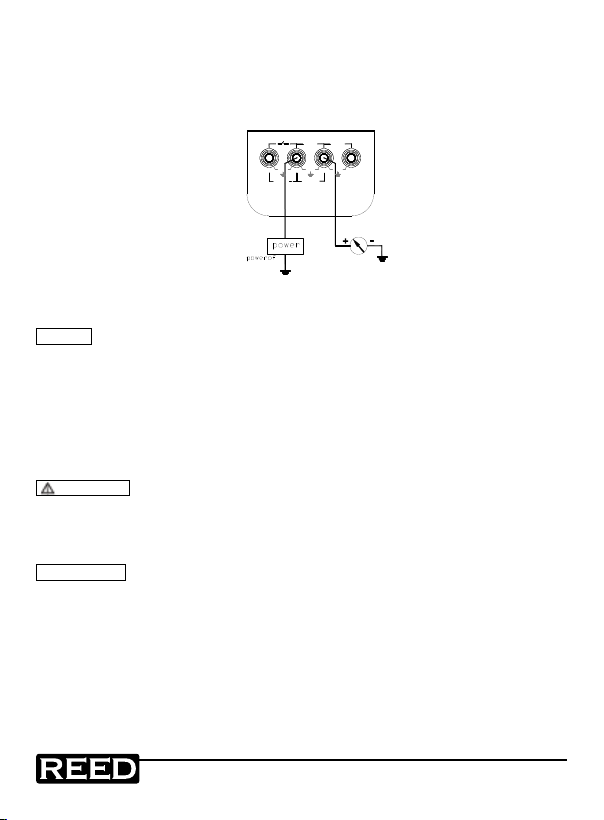
1. Insert one end of the test lead to the ‘XMT’ output jack of the
calibrator and connect the other end with the input terminal of the
user’s instrument as shown in the following diagram:
2. The button-operation is the same as that as indicated in the
Current Output section
NOTE
• Power supply range: 5 to 25VDC
• During an output operation, use a external 24V DC power
supply in order to prolong battery life.
Calibrator Measurement
WARNING
• Never apply more than 30V between any two terminals, or between
any terminal and the ground. Any voltage more than 30V could result
in damage to the calibrator, as well as personal injury.
! CAUTION
• During operation, do not apply a voltage or current exceeding the
measuring range to the input terminal. This could cause damage to
the calibrator.
• During the operation, turn off the instrument before connecting the
calibrator. Connecting to the Calibrator without it being shut it down
may cause damage.
www
REED-Direct.ca
reedinstruments
com
1.800.868.7495[email protected]
11
Page 12
Pantone 534 Blue
Pantone 123 Yellow
Pantone 485 Red
Pantone 123 Yellow
Pantone 534 Blue
Black
Rich Black -
20/20/20/100
Blue - 100/80/30/5
Yellow - 0/27/100/0
Red - 10/100/100/5
Yellow - 0/27/100/0
Blue - 100/80/30/5
Measuring DC Current
+
+LOOP
30V MAX
OUTPUT
+
mA
XMT
30V
MAX
mA
30V
MAX
30V
MAX
V
INPUT
+
M
+LOOP
30V MAX
OUTPUT
+
mA
XMT
30V
MAX
mA
30V
MAX
30V
MAX
V
INPUT
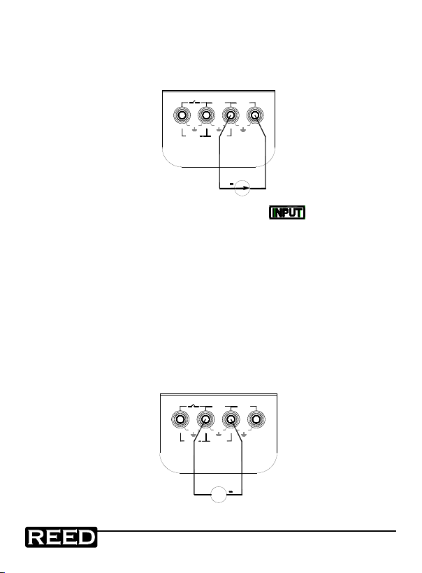
1. Insert one end of the test lead into the mA input terminal and connect the other end to the output of the user’s instrument as shown
in the following diagram:
2. Press the OUTPUT/IN/SW button when
display. It indicates that the calibrator is in an input state.
3. Press the mA%/V button to select mA or %. The value of 0%
indicates 4mA and the value of 100% indicates 20mA.
4. The unit refreshes twice per second. If the measured value
exceeds the measuring range, the display will indicate the symbol
‘-OL-’ (overload).
Measuring DC Voltage
1. Insert one end of the test lead into the V input jack of the
calibrator and connect the other end with the output of the user’s
instrument as show in the following diagram:
www
REED-Direct.ca
reedinstruments
appears on the
com
1.800.868.7495[email protected]
12
Page 13
Pantone 534 Blue
Pantone 123 Yellow
Pantone 485 Red
Pantone 123 Yellow
Pantone 534 Blue
Black
Rich Black -
20/20/20/100
Blue - 100/80/30/5
Yellow - 0/27/100/0
Red - 10/100/100/5
Yellow - 0/27/100/0
Blue - 100/80/30/5
2. Press the OUTPUT/IN/SW button and
+
+LOOP
30V MAX
OUTPUT
+
mA
XMT
30V
MAX
mA
30V
MAX
30V
MAX
V
INPUT
+LOOP
30V MAX
OUTPUT
+
mA
XMT
30V
MAX
mA
30V
MAX
30V
MAX
V
INPUT
will appear on the
display, indicating that the calibrator is in an input state.
3. Press the mA%/V button to select the V function, indicated by ‘V’
appearing on the LCD.
4. The unit refreshes twice per second. If the measured value
exceeds the measuring range, the display will indicate the symbol
‘-OL-’ (overload).
Providing 24V Power Supply for Measuring Loop Current
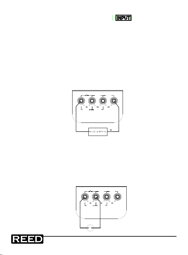
1. Insert the test lead into the +LOOP & mA input jacks of the
calibrator as shown in the following diagram:
2. The operations are the same as described in the Measuring DC
Current instructions.
Measuring Switching Contact Status
1. Insert one end of the test lead into the switching contact
measuring jack of the calibrator and connect the other end to the
switching contact of the user’s instrument as shown in the
following diagram:
www
REED-Direct.ca
reedinstruments
com
13
1.800.868.7495[email protected]
Page 14
Pantone 534 Blue
Pantone 123 Yellow
Pantone 485 Red
Pantone 123 Yellow
Pantone 534 Blue
Black
Rich Black -
20/20/20/100
Blue - 100/80/30/5
Yellow - 0/27/100/0
Red - 10/100/100/5
Yellow - 0/27/100/0
Blue - 100/80/30/5
2. Press the OUTPUT/IN/SW button. The
symbol will appear
followed by the word ‘CLOSE’ or ‘OPEN’ according to the measured switching contact status. When the switching resistance
exceeds 15K, the contact is regarded as at an ‘Off’ state.
Calibration
It is recommended that you calibrate the unit once per year in order
to keep correct accuracies. Contact REED Instruments for assistance
regarding calibration, repairs, warranty, trouble-shooting, and more at:
[email protected].
Battery Replacement
When the appears on the LCD, the batteries need to be replaced.
Follow the instructions below to properly replace the batteries.
1. Turn the power off the meter and remove any test leads that may
be attached to the meter.
2. Remove the holster from the calibrator by releasing the lock in the
indicated direction.
3. Replace the old battery with a new 9V battery. Be sure to check
polarities. Do not mix old batteries with new batteries.
4. Put the battery cover back on and lock it in the indicated direction.
Put the holster back on the calibrator.
www
REED-Direct.ca
reedinstruments
com
14
1.800.868.7495[email protected]
Page 15

Pantone 534 Blue
Pantone 123 Yellow
Pantone 485 Red
Pantone 123 Yellow
Pantone 534 Blue
Black
Rich Black -
20/20/20/100
Blue - 100/80/30/5
Yellow - 0/27/100/0
Red - 10/100/100/5
Yellow - 0/27/100/0
Blue - 100/80/30/5
Notes _________________________________________
________________________________________________
________________________________________________
________________________________________________
________________________________________________
________________________________________________
________________________________________________
________________________________________________
________________________________________________
________________________________________________
________________________________________________
________________________________________________
________________________________________________
________________________________________________
________________________________________________
________________________________________________
________________________________________________
________________________________________________
www
REED-Direct.ca
reedinstruments
com
15
1.800.868.7495[email protected]
Page 16

Pantone 534 Blue
Pantone 123 Yellow
Pantone 485 Red
Pantone 123 Yellow
Pantone 534 Blue
Black
Rich Black -
20/20/20/100
Blue - 100/80/30/5
Yellow - 0/27/100/0
Red - 10/100/100/5
Yellow - 0/27/100/0
Blue - 100/80/30/5
Notes _________________________________________
________________________________________________
________________________________________________
________________________________________________
________________________________________________
________________________________________________
________________________________________________
________________________________________________
________________________________________________
________________________________________________
________________________________________________
________________________________________________
________________________________________________
________________________________________________
________________________________________________
________________________________________________
________________________________________________
________________________________________________
www
REED-Direct.ca
reedinstruments
com
16
1.800.868.7495[email protected]
 Loading...