

Page 1
Model
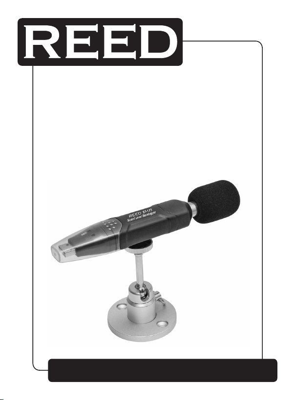
Sound Level Datalogger
Instruction
Manual
ST-173
www
reedinstruments
com
Page 2
Table of Contents
Safety ......................................................................................................... 2
Features ...................................................................................................... 3
Specications ............................................................................................. 4
Instrument Description ............................................................................... 5
Operating Instructions ................................................................................ 6
Warnings .................................................................................................... 7
Software Installation & Operation ............................................................7-8
Instrument Download Data ......................................................................... 9
Calibration Software ............................................................................10-11
Battery Replacement ................................................................................ 11
Safety
Read the following safety information carefully before attempting to operate or service the meter. Use the meter only as specied in this manual.
Environment conditions
• Altitude lower than 2000 meters
• Relatively humidity ≤90%RH
• Operation Ambient 0 ~ 40°C
Maintenance & Cleaning
•
Repairs or servicing that are not covered in this manual should be
performed by qualied personnel only. For service on this or any other
REED product, contact REED Instruments at [email protected].
• Periodically wipe the case with a dry cloth. Do not use solvents or
eradicator on this instrument.
Safety symbol
Complies with EMC
www
reedinstruments
com
2
Page 3

Features
This Sound Level Datalogger is designed for noise assessment; quality
control; illness prevention as well as detection and measurement of all
environmental sounds. Ideal for measuring the sound levels in factories;
schools; ofces; high trafc areas, households, and more.
• This unit conforms to the IEC61672-1 CLASS2 for Sound Level Meters
• NORM (Normal) & PEAK mode
• Data manage: STORE/REAL TIME
• Over range indication
• A & C Weighting
• FAST & SLOW response
• Calibration Software
• Manual & Automatic start
Notes:
• In NORM (Normal) mode, 20 readings will be picked (one reading per
50ms) and the average value of the 20 readings will be stored. At the
same time, a peak max. & a peak min. will be picked wihtin all the
sampling data. If sampling rate takes longer than 10 seconds, the unit
will turn itself off before reaching sampling time to save battery power.
•
In PEAK mode, the DataLogger will always measure data at 50 microsecond intervals. The PEAK value means the MAX. and MIN. reading of
the measurement but not the MAX. and MIN. sampling value. The stored
sampling value is the MAX. of the 20 readings but not the average.
For service on this or any other REED product, contact REED Instruments
at [email protected].
www
reedinstruments
com
3
Page 4

Specifications
Safety Standard: Conforms to IEC61672-1 Class 2
Accuracy: ±1.4dB
Frequency Range: 31.5Hz to 8kHz
Dynamic Range: 50dB
Measuring Range: 30dB to 130dB
DataLogger Capacity: 129920 readings
Sampling Rate: 1 second to 24 hours
Frequency Weighting: A and C
Time Weighting: Fast: 125mm, Slow: 1 second
Microphone: ½” Electret condenser microphone
Operating Indication: Green LED ash
Memory Full Indication: Yellow LED ash
Data Output: USB data trafc
Power: One 3.6V battery, specs: 14250 or 1/2AAA
Electric Current: Normal working is approximately 6mA
Battery Life: Approximately 200 hours
Operation Temperature
& Humidity: 0°C to 40°C, 10&RH to 90&RH
Storage Temperature
& Humidity: -10°C to +60°C, 10&RH to 75&RH
Dimensions: 5.1 x 1.1 x 0.9” (130 x 30 x 25mm)
Weight: 1 oz (20 g)
System Requirements: Windows 2000 or Windows XP or Vista
Minimum Hardware
Requirements: 8M EMS memory, 2M hard disk
and a free USB jack
Includes: Windscreen, transparent cap, software CD,
metal support stand, instruction manual
and battery
www
reedinstruments
com
4
Page 5

Instrument Description
1 - Green LED
2 - Red and
Yellow LED
3 - Power Button:
turn on the
Datalogger
LED Flash Indications
Single LED ash indication
RED LED: The sound level is over the alarm range
(will ash twice-high alarm, once-low alarm).
Yellow LED: Memory is full or datalogger has been stopped
manually (10s/time)
Green LED: Datalogger’s normal working indication
(cycle time can be setup from the software)
Mixed Flash
Red/Green/Yellow: DataLogger is starting to measure (automatic mode)
Green LED: Datalogger start to measure in manual mode
(will ash 6 times in 2 seconds)
Green LED: Datalogger is resetting (will ash 5 times sequentially)
Red LED:
operation manually stopped (will ash 6 times in 2 seconds)
Red & Yellow Alternately: Download the data to PC
RED & Green LED: Low battery indication(10s/time) or the datalogger
was stopped manually (will ash simultaneous)
Datalogger stopping measurements, indication after
www
reedinstruments
com
5
Page 6

Operating Instructions
1. Set up the DataLogger software before use.
2. Under the Manual mode, press and hold the power button for
2 seconds, the DataLogger will start to take the measure.
The LED indicates the status function at the same time
(see LED Flash Indication on page 5 for details).
3. Using the Automatic mode, the DataLogger will start to measure
after setup of the software is complete. The LED indicates the
status function at the same time (see LED Flash Indication
on page 5 for details).
4. As a measurement is being taken, the green LED indicates
it’s working by ashing with the frequency setup in the software.
5. When the DataLogger’s memory is full, the yellow LED will ash
10s/time.
6. As a measurement is being taken, if the measured value exceeds
the alarm range, the red LED will ash (2 times-high alarm,
one time-low alarm).
7. When the battery power is low, the red LED will ash 10s/time.
8. DataLogger data can be read time after time, the readings you
are checking are real time measured (1 to 129920 readings).
9. Without battery, the last 1.5 hours (maximum) of data will be lost.
Other data can be read using the software after the battery
is replaced.
10. When replacing the battery, turn off the meter and open the
battery cover. Then, replace the empty battery with a new
1/2AAA 3.6V battery and re-install the cover.
www
reedinstruments
com
6
Page 7

WARNINGS
1. Do not store or operate the instrument in high temperature
and high humidity environments.
2. When not in use for long periods of time, remove the battery
to avoid battery liquid leakage which will cause damage
to the instrument.
3. When using the instrument in the presence of wind, it is a must
to use the windscreen (included) to avoid picking up undesired
signals (sounds).
4. Keep microphone dry and avoid severe vibrations at all times.
5. Without battery, the last 1.5 hours (maximum) of data will be lost.
6. You have to setup the DataLogger software before using it.
Software Installation & Operation
1. Start windows
2. Insert the CD into the CD-ROM
3. Run SETUP.EXE installation program in le DISK1,
install it to the directory of C:\Program Files\Sound Datalogger\.
4. Setup the USB-driver
5. Plug the Datalogger to the USB port, system will nd and
install the USB-driver. Select the relevant Driver under the
directory which the software installed in the step 3.
6. After Driver installation, a “USB I/O controlled devices”
will appear in the Device Manager. You can nd
“Silabs C8051F320 USB Board” under this directory.
Thus software and driver are installed.
7. Double click the “
“Instrument-DataLogger Setup” to set the sound level DataLogger.
Click “setup” to read the setup information to the DataLogger.
” icon to start the software, then select
www
reedinstruments
com
continued ...
7
Page 8
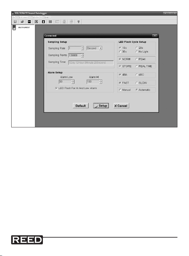
Sampling Setup: Set the time of the sampling rate
(1 second to 24 hours)
Alarm Setup: Set the alarm function
LED Flash for
Hi and Low Alarm: High and low alarm indicates whether
you need the LED Flash or not
LED Flash Cycle Setup: The ash frequency of the indicating LED
Manual/Automatic: Manual or Automatic mode
dBA/dBC: Weighting selection
FAST/SLOW: The Response time selection
NORM/PEAK: The metrical mode selection
STORE/REAL TIME: Data manage
www
reedinstruments
com
8
Page 9
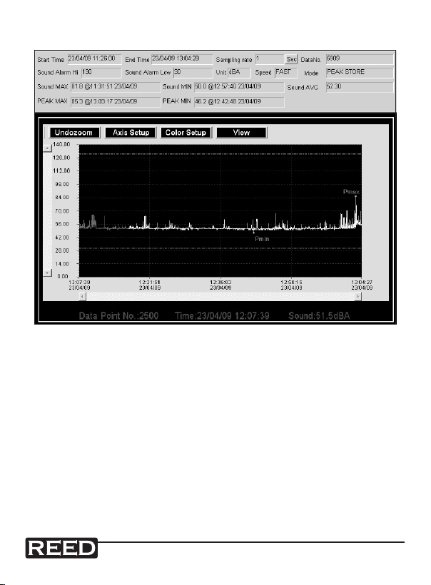
Instrument Download Data
NORM MODE: Sound MAX/Sound MIN means the MAX degree or
MIN degree of the sampling data. It is the average value
of the 20 sampling data. PEAK MAX/PEAK MIN means
the MAX or MIN degree of all the measuring values
(not the average value).
PEAK MODE: Sound MAX/Sound MIN means the MAX degree or
MIN degree of the 20 sampling data.
PEAK MAX/PEAK MIN means the MAX or MIN degree
of all the measuring values.
Note: When a yellow line is displayed this indicates that the
datalogger’s battery power is low.
www
reedinstruments
com
9
Page 10

Calibration Software
When the microphone or the replacement microphone cause an offset in
the reading measurement, the software needs to be calibrated, To begin
this process click on this “ ” icon. The following window will appear:
The “Ajustment Value” is a single calibration value, ranging from -12.5 to
12.5, the value 1.0 is equivalent to 1dB.
Assuming that the reading is 0.5dB higher than the standard value, the
“Ajustment Value” should be set to -0.5.
Press “OK”. The following window will appear:
www
reedinstruments
com
10
Page 11
The “Total calibrated value is -0.5 dB”,calibration over.
The range of the total calibrated value is from -12.5dB to 12.5dB.
For specics regarding the application of this software view the Help le.
Battery Replacement
The datalogger does not lose its stored readings when the battery is
discharged or when the battery is replaced. However, you will not be able
to store data until the battery has been replaced and the stored data has
been downloaded to a PC.
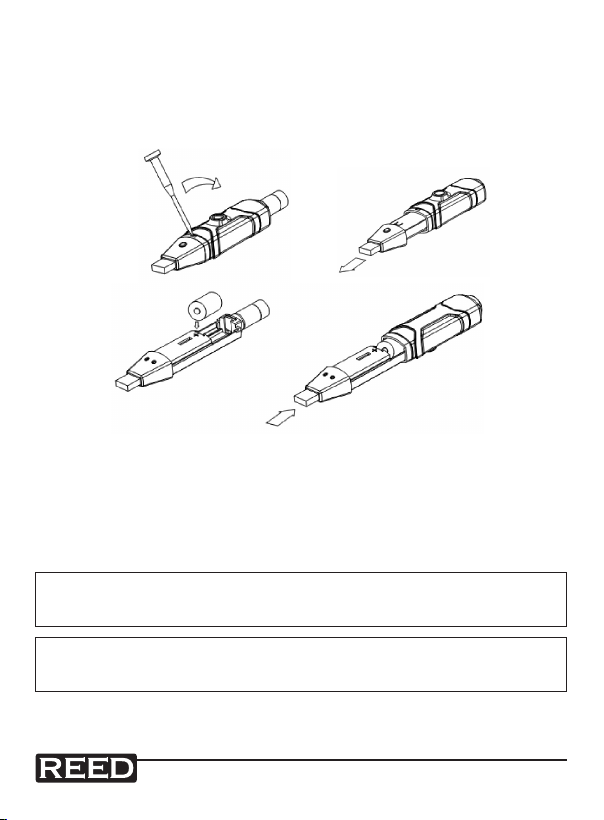
Only use 3.6V lithium batteries. Before replacing the battery, unplug the
unit from the USB port.
NOTE: Leaving the model plugged into the USB port for longer than
necessary will cause some of the battery capacity to be lost.
WARNING: Handle lithium batteries carefully and read warnings on
battery casings. Dispose with in accordance with local regulations.
For service on this or any other REED product, contact REED Instruments
at [email protected].
www
reedinstruments
com
11
Page 12

Notes _________________________________________
________________________________________________
________________________________________________
________________________________________________
________________________________________________
________________________________________________
________________________________________________
________________________________________________
________________________________________________
________________________________________________
________________________________________________
________________________________________________
________________________________________________
________________________________________________
________________________________________________
________________________________________________
________________________________________________
________________________________________________
www
reedinstruments
com
12
 Loading...