

Page 1
1 YEAR
1 AN
R
R
A
N
R
R
A
N
G
A
R
A
N
T
I
E
G
A
R
A
N
T
I
E
W
A
R
R
A
N
T
Y
W
A
R
R
A
N
T
Y
G
A
R
A
N
T
I
E
G
A
R
A
N
T
I
E
1 YEAR1AN
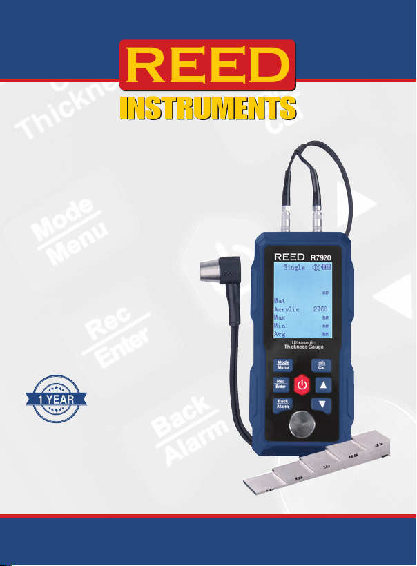
Ultrasonic
Thickness
Gauge
T
A
Y
W
W
Y
A
T
R7920
Instruction
Manual
1-877-849-2127 | [email protected] | www.reedinstruments.com
REED Instruments
Page 2

Table of Contents
Introduction ................................................................................................ 4
Product Quality ........................................................................................... 4
Safety ......................................................................................................... 4
Features ...................................................................................................... 5
Included ...................................................................................................... 5
Specications ............................................................................................. 6
Instrument Description ............................................................................... 7
Display Description .................................................................................... 7
Operating Instructions ........................................................................... 8-12
Initial Calibration .................................................................................... 8
Selecting the Material Sound Velocity ................................................... 9
Preparing the Measurement Surface ..................................................... 9
Taking Thickness Measurements ......................................................... 10
Measurement Methods ................................................................... 10-11
Determining the Sound Velocity for a Material
with a Known Thickness ....................................................................... 11
Auto Power OFF .................................................................................. 11
Enabling/Disabling Alarm Setting......................................................... 12
Data Storage ........................................................................................ 12
Clearing Measurements Results .......................................................... 12
Setup Mode ......................................................................................... 13-18
Select the Material under Test ............................................................. 13
Adjusting the Sound Velocity of the Material under Test ..................... 14
Select Unit of Measure (in/mm)............................................................ 14
continued...
REED Instruments
1-877-849-2127 | [email protected] | www.reedinstruments.com
Page 3

View/Delete Stored Data ...................................................................... 14
View from First/Last Page ................................................................ 15
View from Selected Item .................................................................. 15
Delete by Group Range (Delete the Item) ......................................... 16
Delete All .......................................................................................... 16
System Settings ................................................................................... 16
Enable or Disable the Audible Beep (Sound) ................................... 17
Setting the Backlight Timer .............................................................. 17
Setting the Auto Power OFF Timer .................................................. 17
Setting Alarm Thickness Limits ........................................................ 17
View Device Information ...................................................................... 18
System Reset ....................................................................................... 18
Maintenance ............................................................................................. 18
Cleaning the Test Piece ....................................................................... 18
Protecting the Ultrasonic Sensor ......................................................... 18
Replacing the Ultrasonic Sensor .......................................................... 18
Charging the Battery ................................................................................ 19
Applications .............................................................................................. 19
Accessories and Replacement Parts ....................................................... 19
Product Care ............................................................................................ 19
Appendix A .......................................................................................... 20-25
Material Sound Velocities Table ......................................................20-21
Measurements on Cylindrical Surfaces ................................................ 21
Measuring Compound Profiles ............................................................ 21
Measuring an Un-Parallel Surface ........................................................ 22
Influence of Material's Temperature ..................................................... 22
Material with Large Attenuation ........................................................... 22
Measuring Castings ........................................................................22-23
REED Instruments
1-877-849-2127 | [email protected] | www.reedinstruments.com
continued...
3
Page 4

Preventing Errors ............................................................................23-25
Reference Test Pieces ................................................................. 23-24
Ultra-Thin Material ............................................................................ 24
Rust, Corrosion, and Pits ................................................................. 24
Error in Identifying Material............................................................... 24
Degradation of Probe ....................................................................... 24
Overlapped Material and Compound Material ................................. 25
Influence of Metal Surface Oxidation ............................................... 25
Abnormal Readout of Thickness ...................................................... 25
Utilization and Selection of a Coupling Gel (R7950) ......................... 25
Product Warranty ..................................................................................... 26
Product Disposal and Recycling .............................................................. 26
Product Support ....................................................................................... 26
Introduction
Thank you for purchasing your REED R7920 Ultrasonic Thickness Gauge.
Please read the following instructions carefully before using your instrument.
By following the steps outlined in this manual your meter will provide years
of reliable service.
Product Quality
This product has been manufactured in an ISO9001 facility and has been
calibrated during the manufacturing process to meet stated product
specications. If a certicate of calibration is required, please contact the
nearest authorized REED distributor or authorized Service Center. Please
note an additional fee for this service will apply.
Safety
Never attempt to repair or modify your instrument. Dismantling your
product, other than for the purpose of replacing batteries, may cause
damage that will not be covered under the manufacturer's warranty.
Servicing should only be provided by an authorized service center.
REED Instruments
1-877-849-2127 | [email protected] | www.reedinstruments.com
4
Page 5

Features
• Measures the thickness of steel, cast iron, aluminum, acrylic resin, red
copper, brass, zinc, quartz glass, polyethylene, PVC, grey cast iron and
nodular cast iron
• Easy-to-read backlit LCD display
• User selectable unit of measure (in/mm)
• Internal memory stores up to 300 measurements
• Displays sound velocity at the touch of a button
• User adjustable High/Low alarms
• Automatic material calibration
• Auto shut off and low battery indicator
Included
• Ultrasonic Thickness Gauge
• Ultrasonic Couplant Gel
• Probe
• 5-Step Calibration Block Probe
• USB Cable
• Carrying Case
1-877-849-2127 | [email protected] | www.reedinstruments.com
REED Instruments
5
Page 6

Specifications
Measuring Range: 0.04 to 11.8" (1.00 to 300mm)
Accuracy: <10mm: ±0.1mm
≥10mm: ±(1% rdg. +0.1mm)
Resolution: 0.1mm/0.01mm/0.01"
Velocity Range: 1000 to 9999m/s
(0.039 to 0.394in/µs)
Compatible Materials: Steel, cast iron, aluminum, acrylic
resin, red copper, brass, zinc, quartz
glass, polyethylene, PVC, grey cast
iron and nodular cast iron
Display: 2.4" monochrome dot matrix screen
Backlight: Yes
Probe Length: 3' (91cm)
Probe Diameter: 0.5" (12.7mm)
Internal Memory: Yes (up to 300 readings)
Low Battery Indicator: Yes
Power Supply: Built-in lithium battery
(3.7V 2000mAh)
Battery Life: Approx. 16 hours (Fully Charged)
Product Certications: CE
Operating Temperature: 32 to 104°F (0 to 40°C)
Probe Operating Temperature: 32 to 104°F (0 to 40°C)
Operating Humidity Range: 20 to 80%
Storage Temperature: 14 to 122°F (-10 to 50°C)
Storage Humidity Range: 20 to 70%
Dimensions: 5.5 x 2.6 x 1.12" (140 x 66 x 28.5mm)
Weight: 6.17oz (175g)
1-877-849-2127 | [email protected] | www.reedinstruments.com
REED Instruments
6
Page 7
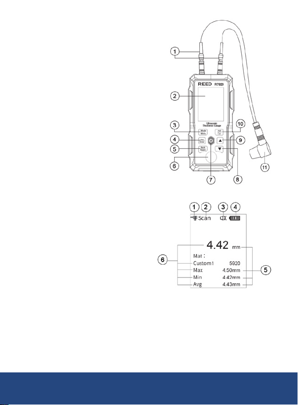
Instrument Description
1. Probe Connectors
2. LCD Display
3. Measurement Mode/
Menu Button
4. Record/Enter Button
5. Back/Alarm Toggle Button
6. Calibration Test Block
7. Power Button
8. Down Arrow
9. Up Arrow
10. Sound Velocity/
Calibration Button
11. Ultrasonic Sensor
Display Description
1. Coupling Indicator
2. Measurement Mode
Indicator
3. Beep Status Indicator
4. Battery Indicator
5. Unit of Measure
6. Measurement/Sound
Velocity Values
1-877-849-2127 | [email protected] | www.reedinstruments.com
REED Instruments
7
Page 8

Operating Instructions
1. Insert the ultrasonic sensor into the probe connector sockets
on the meter.
2. Press the POWER button to turn the meter ON. Press and hold the
POWER button for approx. 2 seconds to turn the meter OFF.
3. The LCD will display the current set sound velocity.
Initial Calibration
1. Select Single measurement mode by pressing the
MODE/MENU button.
2. Place a small drop of coupling gel (R7950) on the 4mm calibration
test block.
3. Press and hold the m/s/Cal button to enter calibration mode as
conrmed by "Please Calibrate" on LCD display.
4. Place the sensor on the calibration test block while ensuring the
coupling indicator appears on the display.
5. While continuing to hold the sensor on the calibration test block,
press the REC/ENTER button when the reading has stabilized.
6. Depending on the selected unit of measure, either "0.16in"
(or "4.0/4.00mm") and "nished!" will appear on the LCD display.
7. Calibration is now complete and the ultrasonic sensor can now be
removed from the calibration test block.
Note: Results from the calibration procedure will automatically save
in the meter. It is not necessary to calibrate the meter each time the
unit is powered on unless measurements appear to be inaccurate. The
calibration procedure conrms both the meter and ultrasonic sensor are
functioning properly.
continued...
1-877-849-2127 | [email protected] | www.reedinstruments.com
REED Instruments
8
Page 9
Selecting the Material Sound Velocity
SPD
5920
m/s
5720 - 6120
Adjust range
90º
Figure 1 Figure 2
Figure 3
≤5mm
90º
1. While the meter is on, press the m/s/CAL button to enter the
pre-loaded material sound velocities menu.
2. Press the and buttons to scroll through the
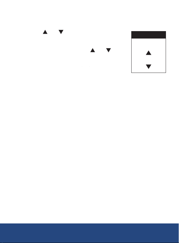
pre-loaded material list.
3. Press the REC/ENTER button to conrm the
SPD
Adjust range
5720 - 6120
material selection and press the and buttons
to adjust the sound velocity of the material under
test if required.
5920
m/s
Note: Each material has an adjustment velocity range
as shown below.
4. Press the REC/ENTER button again to conrm selection and resume
normal operation.
Preparing the Measurement Surface
1. Clean dust, dirt or rust off the object, and remove any coatings
(i.e. paint).
2. Smooth the surface of the object by grinding or polishing,
alternatively, coupling gel with a high viscosity can also be used.
Important Note: In any ultrasonic measurement scenario, the shape and
roughness of the desired test material are of great importance. Rough,
uneven surfaces will prevent the ultrasonic sensor from seating properly
against the surface, thus limiting the penetration of ultrasound through the
material, resulting in unstable and therefore, unreliable measurements.
continued...
1-877-849-2127 | [email protected] | www.reedinstruments.com
REED Instruments
9
Page 10

Taking Thickness Measurements
90º
Figure 1 Figure 2
Figure 3
≤5mm
1. Set the sound velocity on the meter (See the Selecting the Material
Sound Velocity section for details).
2. Press the MODE/MENU button to select between Single and
Continuous (Scan) measurement mode (See the Measurement
Methods section for details).
3. Apply coupling gel on the material under test and place the sensor
rmly against the desired measurement area.
Note: For most applications a single droplet of coupling gel is sufcient.
4. Verify that the coupling indicator appears on the LCD display.
5. Read the measurement on the LCD display.
6. When the ultrasonic sensor is removed the value will stay on the LCD
and the coupling indicator will disappear.
7. Press and hold the REC/ENTER button to save the measurement
if applicable.
Note: If the coupling indicator does not appear on the display, or
the measured values appear to be erratic, verify that there is an
adequate amount of coupling gel in between the ultrasonic sensor
and the material under test. It is important that the ultrasonic
sensor sits flat against the material.
Measurement Methods
There are four base measurement methods:
1. Single measurement method: This method involves measuring the
thickness at a single point.
2. Double measurement method: This method involves performing
two thickness measurements near a single spot
rotating the ultrasonic sensor from 0° to 90°
with respect to the split face (Figure 1). Take
the smaller of the two indicated values as the
thickness of the material.
continued...
1-877-849-2127 | [email protected] | www.reedinstruments.com
REED Instruments
10
Page 11
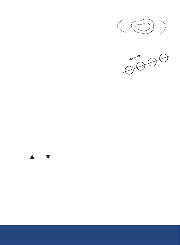
3. Multi-point measurement: This
Figure 3
≤5mm
method involves performing a number of
measurements within a circle having a
maximum diameter of about 1.18" (30mm)
(Figure 2). Take the minimum indicated
value as the thickness of the material.
4. Continuous measurement (scan):
Continuous measurement method involves
≤5mm
taking continuous measurements along
a specied line according to the single
measurement method, at intervals of 5mm
or less (Figure 3). Take the minimum indicated
value as the thickness of the material.
Figure 3
Determining the Sound Velocity for a Material with a
Known Thickness
The sound velocity of a material can be measured using a test piece with
a known thickness. Select a test piece with a minimum wall thickness
of 20.0mm.
1. Measure the test piece with a caliper or micrometer to
conrm thickness.
2. Apply coupling gel on the material, place the sensor rmly against
the desired measurement area.
3. Remove the ultrasonic sensor from the measurement area and adjust
the measuring display until the actual thickness is met by pressing
the and buttons and press the REC/ENTER button to
conrm selection.
4. The LCD will now display the sound velocity of the test piece.
5. Press the REC/ENTER button to save the sound velocity.
6. At this point, the correct thickness measurement can be achieved by
measuring the same material with the saved sound velocity.
Auto Power OFF
To preserve battery life, the meter is programmed to turn itself OFF after
approximately 5 minutes of inactivity. To adjust the auto power off time,
see the Setting the Auto Power OFF Timer section for details.
REED Instruments
1-877-849-2127 | [email protected] | www.reedinstruments.com
continued...
11
Page 12

Enabling/Disabling Alarm Setting
The R7920 will alarm when the measured value is beyond the pre-set
limits. When the measurement is lower or higher than the pre-set standard
value limit, the alarm will sound. To enter the alarm limits, see the Setting
the Alarm Thickness Limits section for details.
Press and hold the BACK/ALARM button to turn the alarm function
ON ( ) or OFF ( ).
Data Storage
When taking a measurement in single or continuous mode, press the
REC/ENTER button to save the measurement if applicable.
Note: Each data record includes the current measurement,
MAX, MIN, AVG values and material sound velocity. A maximum
of 300 groups of data can be stored. While in the continuous
measurement mode, the data can only be saved after the probe is
removed from the test piece.
Clearing Measurements Results
When taking a measurement in single or continuous mode, press the
BACK/ALARM button to clear the current measurements.
Note: Each data record includes the current measurement,
MAX, MIN, AVG values and material sound velocity. While in the
continuous measurement mode, the measurements can only be
cleared after the probe is removed from the test piece.
1-877-849-2127 | [email protected] | www.reedinstruments.com
REED Instruments
12
Page 13
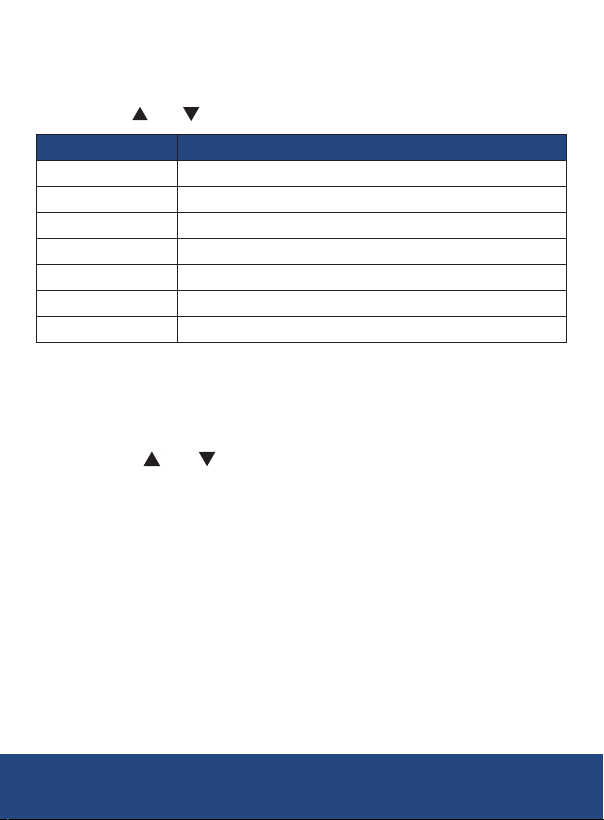
Setup Mode
1. Press and hold the MODE/MENU button for 2 seconds to enter
Setup Mode.
2. Use the and arrows to scroll through the following parameters:
Parameter Description
Material Select the Material Under Test
Speed Adjust Sound Velocity of the Material Under Test
Unit Select Unit of Measure
Records View/Delete Stored Data
Setting Access Settings Menu
About View Device Information
Reset Reset to Factory Settings
3. Once the appropriate parameter has been selected, follow the
instructions below.
Select the Material under Test
1. Press the REC/ENTER button when "Material" appears on the LCD.
2. Press the and buttons to scroll through the list of
pre-loaded materials.
3. Press the REC/ENTER button to conrm selection and return to the
Setup Menu screen.
Note: At any time, press the BACK/ALARM button while in the setup
menu screen to exit the Setup mode and resume normal operation.
continued...
1-877-849-2127 | [email protected] | www.reedinstruments.com
REED Instruments
13
Page 14
Adjusting the Sound Velocity of the Material under Test
90º
Figure 1 Figure 2
≤5mm
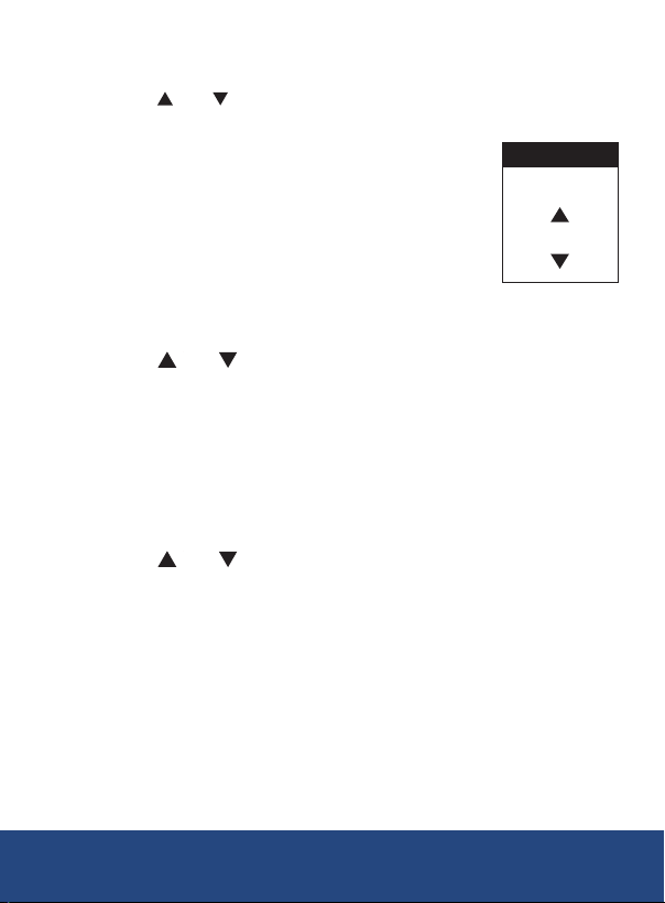
1. Press the REC/ENTER button when "Speed" appears on the LCD.
2. Press the and buttons to adjust the sound velocity of the
material under test if required.
Note: Each material has an adjustment velocity range
as shown below.
3. Press the REC/ENTER button to conrm selection
SPD
Adjust range
5720 - 6120
and return to the Setup Menu screen.
Note: At any time, press the BACK/ALARM button
while in the setup menu screen to exit the Setup mode
5920
m/s
and resume normal operation.
Select Unit of Measure (in/mm)
1. Press the REC/ENTER button when "Unit" appears on the LCD.
2. Press the and buttons to select from 0.01in, 0.01mm and 0.1m
units of measure.
3. Press the REC/ENTER button while in the setup menu screen to exit
the Setup mode and resume normal operation.
Note: At any time, press the BACK/ALARM button while in the setup
menu screen to exit the Setup mode and resume normal operation.
View/Delete Stored Data
1. Press the REC/ENTER button when "Records" appears on the LCD.
2. Press the and buttons to scroll through the following
parameters within the stored data function:
a) First Page
b) Last Page
c) Selected Item
d) Delete the Item
e) Delete All
Follow the instructions below to adjust each setting.
Note: If there is no data in the memory, the meter will display
"No Records" and return to the menu screen.
1-877-849-2127 | [email protected] | www.reedinstruments.com
REED Instruments
continued...
14
Page 15
View from First/Last Page
1. Press the REC/ENTER button to enter the selected parameter.
2. Press the REC/ENTER button again to activate les to view.
3. Press the and buttons to scroll through the list of saved les.
4. Press the REC/ENTER button to see the details of the
measured data.
5. While in the selected measurement data screen, press
the and buttons to scroll through the measurement data
screens for the other saved les.
6. Press the BACK/ALARM button three times to return to the stored
data parameters screen.
Note: At any time, press the BACK/ALARM button while in the setup
menu screen to exit the Setup mode and resume normal operation.
View from Selected Item
1. Press the REC/ENTER button to enter the selected parameter.
2. Press the REC/ENTER button again to skip to the required digit.
3. Press the
4. Press the REC/ENTER button to conrm and skip to the next digit.
5. After each value has been selected and conrmed, the meter will
automatically search for the data les matching the search criteria.
6. Press the REC/ENTER button again to activate les to view.
7. Press the and buttons to scroll through the list of saved les.
8. Press the REC/ENTER button to see the details of the
measurement data.
9. While in the selected measurement data screen, press
the and buttons to scroll through the measurement data
screens for the other saved les.
10. Press the BACK/ALARM button three times to return to the stored
data parameters screen.
Note: At any time, press the BACK/ALARM button while in the setup
menu screen to exit the Setup mode and resume normal operation.
and buttons until the desired value is reached.
continued...
1-877-849-2127 | [email protected] | www.reedinstruments.com
REED Instruments
15
Page 16
Delete by Group Range (Delete the Item)
1. Press the REC/ENTER button to enter the selected parameter.
2. Press the REC/ENTER button again to skip to the required digit.
3. Press the and buttons until the desired value is reached.
4. Press the REC/ENTER button to conrm and skip to the next digit.
5. After each value has been selected and conrmed, the meter will ask
to conrm deletion of the specic group range.
6. Press the and buttons to select between "Yes" and "No".
7. Press the REC/ENTER button to conrm selection.
8. Press the BACK/ALARM button to return to the stored data
parameters screen.
Note: At any time, press the BACK/ALARM button while in the setup
menu screen to exit the Setup mode and resume normal operation.
Delete All
1. Press the REC/ENTER button to enter the selected parameter.
2. Press the
3. Press the REC/ENTER button to conrm selection.
Note: At any time, press the BACK/ALARM button while in the setup
menu screen to exit the Setup mode and resume normal operation.
and buttons to select between "Yes" and "No".
System Settings
1. Press the REC/ENTER button when "Settings" appears on the LCD.
2. Press the
parameters within the system settings function:
a) Sound
b) Backlight
Follow the instructions below to adjust each setting.
and buttons to scroll through the following
c) Power OFF
d) Alarm
continued...
1-877-849-2127 | [email protected] | www.reedinstruments.com
REED Instruments
16
Page 17
Enable or Disable the Audible Beep (Sound)
1. Press the REC/ENTER button when "Sound" appears on the LCD.
2. Press the
3. Press the REC/ENTER button to conrm selection.
Note: At any time, press the BACK/ALARM button while in the setup
menu screen to exit the Setup mode and resume normal operation.
Setting the Backlight Timer
1. Press the REC/ENTER button when "Back light" appears
on the LCD.
2. Press the
60-180 seconds.
3. Press the REC/ENTER button to conrm selection.
Note: At any time, press the BACK/ALARM button while in the setup
menu screen to exit the Setup mode and resume normal operation.
Setting the Auto Power OFF Timer
1. Press the REC/ENTER button when "Power off" appears
on the LCD.
2. Press the
120-300 seconds.
3. Press the REC/ENTER button to conrm selection.
Note: At any time, press the BACK/ALARM button while in the setup
menu screen to exit the Setup mode and resume normal operation.
Setting Alarm Thickness Limits
1. Press the REC/ENTER button when "Alarm" appears on the LCD.
2. Press the
3. Press the REC/ENTER button to conrm selection and to set the
allowable thickness limit.
4. Press the
5. Press the REC/ENTER button to conrm selection.
Note: At any time, press the BACK/ALARM button while in the setup
menu screen to exit the Setup mode and resume normal operation.
1-877-849-2127 | [email protected] | www.reedinstruments.com
and buttons to select between "Yes" and "No".
and buttons to set the backlight timer between
and buttons to set the backlight timer between
and buttons to set the standard thickness value.
and buttons to set the thickness limit value.
continued...
REED Instruments
17
Page 18

View Device Information
1. Press the REC/ENTER button when "About" appears on the LCD to
view the device information.
2. Press the BACK/ALARM button to return to the Setup Menu screen.
Note: At any time, press the BACK/ALARM button while in the setup
menu screen to exit the Setup mode and resume normal operation.
System Reset
1. Press the REC/ENTER button when "Reset" appears on the LCD.
2. Press the and buttons to select between "Yes" or "No".
3. Press the REC/ENTER button to conrm selection.
Note: At any time, press the BACK/ALARM button while in the setup
menu screen to exit the Setup mode and resume normal operation.
Maintenance
Cleaning the Test Piece
After taking a measurement, clean the test pieces to prevent them from
rusting. If the pieces are not to be used for a long period of time, coat
them with oil to prevent rust.
Protecting the Ultrasonic Sensor
Be sure to clean the ultrasonic sensor and cable after each use. Grease,
oil and dust will cause the cable to dry out and shorten life expectancy.
The temperature of the surface being measured should not
exceed 140°F (60°C).
Replacing the Ultrasonic Sensor
The degradation and wear of the probe's interlayer plate will inuence
measurements. Replace the probe when the following occurs:
• The same value is always displayed when measuring different
thicknesses or;
• A measurement displays no value.
1-877-849-2127 | [email protected] | www.reedinstruments.com
REED Instruments
18
Page 19

Charging the Battery
1. Connect the R7920 via the included cable to a USB port on a PC or
into a wall outlet using a USB Power Adapter (not included) to charge
the Li-ion battery.
2. Charge the meter until the battery indicator appears full.
3. Remove the charging cable.
Applications
• Monitoring and verifying pipes and pressure vessels
• Industrial manufacturing
Accessories and Replacement Parts
• R7920-PROBE Replacement Probe
• R7950 Ultrasonic Couplant Gel
• R7950/12 Ultrasonic Couplant Gel, Pack of 12
• R7950/5L Ultrasonic Couplant Gel, 5L
• R9060 5-Step Calibration Block
• R8888 Deluxe Hard Carrying Case
Don't see your part listed here? For a complete list of all accessories and
replacement parts visit your product page on www.REEDInstruments.com.
Product Care
To keep your instrument in good working order we recommend the following:
• Store your product in a clean, dry place.
• Charge the battery as needed.
• If your instrument isn't being used for a period of one month or longer
please remove the battery.
• Clean your product and accessories with biodegradable cleaner. Do not
spray the cleaner directly on the instrument. Use on external parts only.
1-877-849-2127 | [email protected] | www.reedinstruments.com
REED Instruments
19
Page 20
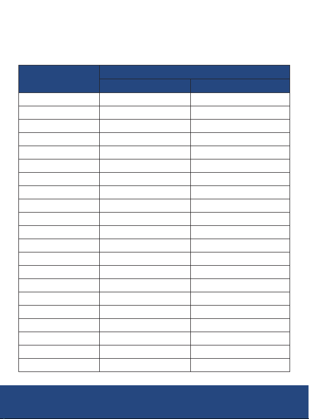
Appendix A
Material Sound Velocities Table
Note: The sound velocities listed below are for reference only.
Material
User dene 1 0.233 5920
User dene 2 0.233 5920
User dene 3 0.233 5920
Aluminum 0.250 6340-6400
Steel, common 0.233 5920
Steel, stainless 0.226 5740
Brass 0.173 4399
Cooper 0.186 4720
Iron 0.233 5930
Cast Iron 0.173-0.229 4400-5820
Lead 0.094 2400
Nylon 0.105 2680
Silver 0.142 3607
Gold 0.128 3251
Zinc 0.164 4170
Titanium 0.236 5990
Tin 0.117 2960
Acrylic resin 0.109 2760
Epoxy resin 0.100 2540
Ice 0.157 3988
Nickel 0.222 5639
in/µs m/s
REED Instruments
1-877-849-2127 | [email protected] | www.reedinstruments.com
Description
continued...
20
Page 21
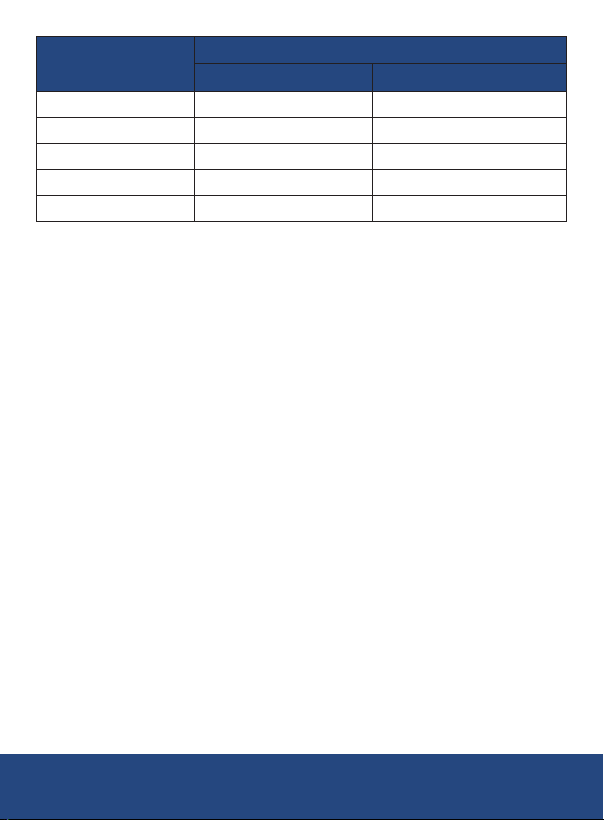
Material
Plexiglass 0.106 2692
Porcelain 0.230 5842
PVC 0.094 2388
Quartz glass 0.222 5639
Rubber, vulcanized 0.091 2311
in/µs m/s
Description
Measurements on Cylindrical Surfaces
When measuring cylindrical material, such as pipes or oil tubes, it is
important to properly adjust the angle between the ultrasonic sensor's
crosstalk interlayer plate and the axial line of the material being measured.
1. Couple the sensor with the material being measures.
2. Make the sensor's crosstalk interlayer plate perpendicular or parallel
to the axial line of the material under test.
3. Shake the sensor vertically along the axial line of the material under
test, the readouts displayed on screen will change regularly.
4. Use the minimum readout.
The standard for selecting the angle between the sensor's crosstalk
interlayer plate and the axial line of the material under test depends on
the curvature of the material under test. For a pipe with a large diameter
the sensor's crosstalk interlayer plate should be perpendicular to the axial
line of the material under test. For a pipe with small diameter, the sensor's
crosstalk interlayer plate can be both parallel and perpendicular to the
axial line of the material under test, and take the minimum readout as
the thickness.
Measuring Compound Profiles
When the material being measured has a compound prole (such as
a bend in a pipe), one can use the procedures to measure cylindrical
surfaces. The exception is that one should have two analyses and get
two results when the sensor's crosstalk interlayer plate is both parallel
and perpendicular to the axial line of the material under test. Take the
minimum readout as the material thickness.
REED Instruments
1-877-849-2127 | [email protected] | www.reedinstruments.com
continued...
21
Page 22

Measuring an Un-Parallel Surface
To get a satisfactory ultrasonic response, the other surface of the material
under test must be parallel to or co-axial with the surface being measured,
otherwise it will cause a measuring error or even provide no displayed
reading.
Influence of Material’s Temperature
Both the thickness and transmitting speed of ultrasonic waves are
inuenced by temperature. If there is a high requirement of measuring
accuracy, please use one of the comparison methods listed below:
1. Use a test piece of the same material being measured, under the
same temperature.
2. Obtain the temperature compensation coefcient.
3. Use this coefcient to correct the actual measurement of the material
being tested.
Material with Large Attenuation
Material with porous and coarse particles (such as bre) will cause a large
scatter and energy attenuation in the ultrasonic wave. This will cause
abnormal readings or provide no readings on the display (generally, the
abnormal readings are less than the actual thickness). These type of
materials cannot be measured by our ultrasonic thickness gauges.
Measuring Castings
Castings will cause large attenuations in sound energy due to coarse
crystal particles and a not-so-dense structure. The attenuation is due to
the material's scatter and absorption of sound energy. Coarse out-phase
structures and coarse crystal particles will cause abnormal reection (i.e.
a grass-shaped or tree-shaped echo) resulting in errors in the readings.
When the crystal particle is coarse, the anisotropy in exibility in metal's
crystallizing direction will be obvious. This results in difference in sound
velocities in different directions, with the maximum difference being up to
5.5%. The compactness in different positions of the workpiece is different,
which will also cause difference in sound velocity. All of these will produce
inaccuracies in the measurements.
REED Instruments
1-877-849-2127 | [email protected] | www.reedinstruments.com
continued...
22
Page 23

While measuring castings pay attention to the following:
1. When measuring casting with an un-machined surface use engine
oil, consistent grease, or water glass as a coupling gel.
2. Calibrate the sound velocity for the material under test with a
standard test piece having the same material and measuring
direction as that of the material being measured.
3. If necessary, take a 2-point calibration.
Preventing Errors
Reference Test Pieces
To maintain high accuracy when taking measurements of different
materials, it is important to use a standard test piece that resembles
the material and conditions being measured. The ideal reference test
pieces should be a group of test pieces with different thicknesses made
of the same materials that is going to be measured. The test pieces can
provide calibrating factors for the meter (such as the microstructure of the
material, heat-treating condition, direction of particles, surface roughness,
etc.). To meet the highest requirements of accuracy a set of reference test
pieces are critical.
Under most situations satisfactory measuring accuracies can be met
with only one reference test piece. This should be the same material and
similar thickness to the material under test. Take an even-surfaced object,
measure it by using a micrometer, then use it as a test piece.
For thin material, when its thickness is near to the low limit of the sensor's
measuring range, use a test piece to determine the accurate low limit.
Never measure a material with a thickness lower than the low limit.
When the material under test is thick, especially an alloy with complex
internal structure, select a test piece similar to the object from a group of
test pieces, to provide an idea of calibration.
For most casting and forging, their internal structures have some
direction. In different directions, the sound velocity will experience some
change. To solve this problem, the test piece should have an internal
structure with same direction as that of the material under test, and the
transmitting direction of sound wave in it should also be same as that of
the material.
continued...
1-877-849-2127 | [email protected] | www.reedinstruments.com
REED Instruments
23
Page 24

Under certain circumstances, referring to a material speed-of-sound
table can replace reference test pieces. The value in the speed-of-sound
table may have some difference from the actual measured values due to
difference in the material's physical and chemical characteristics. This is
usually used for measuring low-carbon steel, and can only be taken as a
rough measurement.
Ultra-thin Material
An error will occur when the thickness of a material under test is less
than the low limit of the ultrasonic sensor. When necessary, measure
the minimum limit thickness by comparing it with test pieces. When
measuring an ultra-thin material, sometimes errors called "double
refraction" may occur. This results in a displayed measuring reading that is
twice the actual thickness of the material under test. Another error result
is called "pulse envelop or cyclic leap". This results in the measured value
being larger than the actual thickness. To prevent these kinds of errors
repeat the measurement to conrm the results.
Rust, Corrosion, and Pits
Rust and pits on the surface of the object will cause irregular change in
the measured reading. In extreme situations it will even cause no readings
on the display. To avoid errors, orient the sensor's crosstalk interlayer
plate in different directions to take multiple measurements.
Error in Identifying Material
If calibrating the meter with one material and then measure another
material, an error will occur. Be careful in selecting the correct
sound velocity.
Degradation of Probe
The surface of the probe is allyl resin. Over time its roughness will increase
resulting in reduced sensitivity. If it is determined that this is the reason for
the errors, grind the surface with sandpaper or oilstone to make it smooth
again. If the readings are still not stable, the sensor must be replaced.
continued...
1-877-849-2127 | [email protected] | www.reedinstruments.com
REED Instruments
24
Page 25

Overlapped Material and Compound Material
It is impossible to measure uncoupled overlapped material because
the ultrasonic wave can't pass through an uncoupled space. Since the
ultrasonic wave can't transmit in a compound material in even speed,
an ultrasonic thickness-gauge cannot be used to measure overlapped
material and compound material.
Influence of Metal Surface Oxidation
Some metals can produce a dense oxidation layer on the surface, such
as aluminum. Even though the layer is in close contact with the substrate
and provides no obvious interface, the ultrasonic wave will have different
transmitting speeds in these two materials which will cause an error.
In addition, different thicknesses in oxidation layers will cause different
errors. Make a reference piece from a batch of objects by measuring with
a micrometer or calliper, and using it to calibrate the instrument.
Abnormal Readout of Thickness
The operator should be able to identify an abnormal measuring reading.
Generally the rust, corrosion, pit, and internal defect of the material under
test will cause abnormal measuring readings.
Utilization and Selection of a Coupling Gel (R7950)
Coupling gel is used for transmitting high-frequency energy between the
ultrasonic gel and the material under test. If the type of gel or utilization
is wrong, or the utilization it will cause an error. For most applications a
single droplet of coupling gel coated evenly is sufcient. When measuring
a smooth surface use a gel with low viscosity (such as the coupling gel
provided or light engine oil). When measuring a coarse object surface,
vertical surface or top surface, use a gel with high viscosity (such as
glycerin grease, consistent grease, and lubricating grease, etc.).
1-877-849-2127 | [email protected] | www.reedinstruments.com
REED Instruments
25
Page 26
Product Warranty
REED Instruments guarantees this instrument to be free of defects
in material or workmanship for a period of one (1) year from date of
shipment. During the warranty period, REED Instruments will repair or
replace, at no charge, products or parts of a product that proves to be
defective because of improper material or workmanship, under normal
use and maintenance. REED Instruments total liability is limited to repair
or replacement of the product. REED Instruments shall not be liable for
damages to goods, property, or persons due to improper use or through
attempts to utilize the instrument under conditions which exceed the
designed capabilities. In order to begin the warranty service process,
please contact us by phone at 1-877-849-2127 or by email at
[email protected] to discuss the claim and determine the
appropriate steps to process the warranty.
Product Disposal and Recycling
Please follow local laws and regulations when disposing or recycling your
instrument. Your product contains electronic components and must be
disposed of separately from standard waste products.
Product Support
If you have any questions on your product, please contact your authorized
REED distributor or REED Instruments Customer Service by phone at
1-877-849-2127 or by email at [email protected].
Please visit www.REEDInstruments.com for the most
up-to-date manuals, datasheets, product guides and software.
Product specifications subject to change without notice.
All rights reserved. Any unauthorized copying or reproduction of this
manual is strictly prohibited without prior written permission from
REED Instruments.
1-877-849-2127 | [email protected] | www.reedinstruments.com
REED Instruments
26
Page 27

Page 28

Page 29

TEST & MEASURE
WITH CONFIDENCE
Access our
Product Catalog
Over 200 portable test and
measurement instruments
1-877-849-2127 | [email protected] | www.reedinstruments.com
REED Instruments
Page 30

 Loading...