

Page 1
Multifunction
White background
W
A
R
R
A
N
T
Y
W
A
R
R
A
N
T
Y
2 YEAR
R
R
A
R
R
A
N
G
A
R
A
N
T
I
E
G
A
R
A
N
T
I
E
2 ANS
Process
Calibrator
N
T
A
Y
W
2 YEAR
W
Y
A
T
R5850
Instruction
Manual
REED Instruments
1-877-849-2127 | [email protected] | www.reedinstruments.com
Page 2

Table of Contents
Introduction ................................................................................................ 4
Product Quality .......................................................................................... 4
Safety ......................................................................................................4-5
Features ...................................................................................................... 5
Included ..................................................................................................... 5
Specications ....................................................................................... 6-12
Measure Function .................................................................................... 6
Thermocouples .....................................................................................6-7
RTDs ..................................................................................................... 8-9
Source Function ....................................................................................... 9
Thermocouples ...................................................................................9-11
RTDs ...................................................................................................... 11
Function Specifications .......................................................................... 12
General Specifications ........................................................................... 12
Instrument Description ........................................................................ 13-15
Buttons .............................................................................................. 14-15
Display Description .................................................................................. 16
Operating Instructions ........................................................................ 17-18
Power ON/OFF ....................................................................................... 17
Setup Mode ........................................................................................... 17
Set Auto Power Off ................................................................................ 17
Adjust the LCD Brightness Level ........................................................... 18
Select the Temperature Unit of Measure ............................................... 18
Enable/Disable Remote Control Commands ......................................... 18
Enable/Disable the Beeper ..................................................................... 18
Measurement Modes ..........................................................................19-27
Millivolt Measurement (Upper Display) ................................................... 19
Millivolt Measurement (Lower Display) ................................................... 19
Voltage Measurement (Upper Display) ................................................... 20
Voltage Measurement (Lower Display) ................................................... 20
REED Instruments
1-877-849-2127 | [email protected] | www.reedinstruments.com
continued...
2
Page 3

MilliAmp Measurement (Upper Display) ................................................. 21
MilliAmp Measurement (Lower Display) ................................................. 21
Current Measurement with Loop Power (Upper Display) ...................... 22
Resistance Measurement (Upper Display) ............................................. 22
Resistance Measurement (Lower Display) ............................................. 23
Continuity Measurement (Upper Display) .............................................. 23
Frequency Measurement (Lower Display) .............................................. 24
Pulse Measurement (Lower Display) ...................................................... 24
Switch Quantity Measurement (Lower Display) ..................................... 25
Thermocouple Measurement (Lower Display) .................................. 25-26
RTD Measurement ................................................................................. 27
Source Modes (Lower Display) ...........................................................28-36
Millivolt Output ....................................................................................... 28
Voltage Output ....................................................................................... 28
Sourcing 4 to 20mA ............................................................................... 29
Simulating a 4 to 20mA Transmitter ..................................................29-30
Resistance Output ................................................................................. 30
Frequency Output .................................................................................. 31
Pulse Output .....................................................................................31-32
Switch Quantity Output .......................................................................... 32
Thermocouple Output ............................................................................ 33
RTD Output ............................................................................................ 34
Stepping the Output ......................................................................... 35-36
Auto Ramping the Output ...................................................................... 36
Remote Control Commands .................................................................... 36
Charging the Battery ................................................................................ 37
Applications ............................................................................................. 37
Accessories and Replacement Parts ....................................................... 37
Product Care ............................................................................................ 37
Product Warranty ..................................................................................... 38
Product Disposal and Recycling .............................................................. 38
Product Support ...................................................................................... 38
1-877-849-2127 | [email protected] | www.reedinstruments.com
REED Instruments
3
Page 4

Introduction
Thank you for purchasing your REED R5850 Multifunction Process Calibrator.
Please read the following instructions carefully before using your instrument.
By following the steps outlined in this manual your meter will provide years
of reliable service.
Product Quality
This product has been manufactured in an ISO9001 facility and has been
calibrated during the manufacturing process to meet the stated product
specications. If a certicate of calibration is required please contact the
nearest authorized REED distributor or authorized Service Center. Please
note an additional fee for this service will apply.
Safety
• Do not apply more than the rated voltage, as marked on the calibrator,
between the terminals, or between any terminal and earth ground
(30V 24mA max all terminals).
• Before each use, verify the calibrator's operation by measuring a
known voltage.
• Follow all equipment safety procedures.
• Never touch the probe to a voltage source when the test leads are
plugged into the current terminals.
• Do not use the calibrator if it is damaged. Before using the calibrator,
inspect the case. Pay particular attention to the insulation surrounding
the connectors.
• Select the proper function and range for testing.
• Make sure the battery door is closed and latched before operating
the calibrator.
• Remove test leads from the calibrator before opening the battery door.
•
Inspect the test leads for damaged insulation or exposed metal. Check test
leads continuity. Replace damaged test leads before using the calibrator.
• When using the probes, keep ngers away from the probe contacts.
Keep ngers behind the nger guards on the probes.
• Connect the common test lead before connecting the live test lead. When
disconnecting test leads, disconnect the live test lead rst.
REED Instruments
1-877-849-2127 | [email protected] | www.reedinstruments.com
continued...
4
Page 5

• Do not use the calibrator if it operates abnormally. Protection may be
impaired. When in doubt, have the calibrator serviced.
• Do not operate the calibrator around explosive gas, vapor, or dust.
• Disconnect test leads before changing to another measure or
source function.
• Never attempt to repair or modify the instrument. Dismantling the
product, other than for the purpose of replacing batteries, may cause
damage that will not be covered under the manufacturer's warranty.
Servicing should only be provided by an authorized service center.
Features
• Rugged design stands up to eld use
• Measures/Sources volts, mA, RTDs, thermocouples, frequency, and ohms
• 0.02% output and measurement accuracy
• Easy-to-read measure/source screen lets you view input and
output simultaneously
• Perform fast linearity tests with auto step and auto ramp features
• Powers transmitters during the test using a loop supply with
simultaneous mA measurement
• Measures and outputs 10 types of RTDs and 12 types of TC signals
• Rechargeable Ni-MH battery
• Adjustable brightness provides better visibility in poor light
• Store frequently-used test setups for later use
• Low battery indicator and auto shut-off
Included
• Multifunction Process Calibrator
• Test Leads
• Test Clips
• Type K Thermocouple Wire Probe
• USB Cable
• Power Adapter
• Carrying Case
1-877-849-2127 | [email protected] | www.reedinstruments.com
REED Instruments
5
Page 6
Specifications
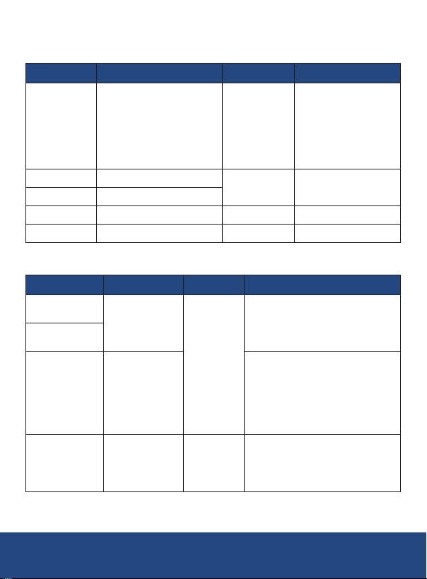
Measure Function
Function Range Resolution Accuracy
50mV: ±(0.02% +10)
DC Voltage
DC Current 20mA at 0 to 24mA
Loop Current 20mA (loop) at 0 to 24mA
Resistance 500, 5000Ω 0.01, 0.1Ω ±(0.05% +10)
Frequency 100Hz, 1, 10, 100kHz 0.01, 0.1, 1Hz ±(0.01% +1)
50, 500mV,
30V (upper display),
50V (lower display)
0.001, 0.01,
1mV, 0.001V
0.001mA ±(0.02% +2)
Thermocouples
Thermocouple
Type R
Type S
Type B
Type E
Range
32 to 3212.6°F
(0 to 1767°C)
1112 to 3308°F
(600 to 1820°C)
-58 to 1832°F
(-50 to 1000°C)
Resolution
1°F/°C
0.1°F/°C
Accuracy
32 to 932°F (0 to 500°C):
±3.24°F (±1.8°C)
932 to 3212.6°F (500 to 1767°C):
±2.7°F (±1.5°C)
1112 to 1472°F (600 to 800°C):
±3.96°F (±2.2°C)
1472 to 1832°F (800 to 1000°C):
±3.24°F (±1.8°C)
1832 to 3308°F (1000 to 1820°C):
±2.52°F (±1.4°C)
-58 to 32°F (-50 to 0°C):
±1.62°F (±0.9°C)
32 to 1832°F (0 to 1000°C):
±2.7°F (±1.5°C)
500mV: ±(0.02% +5)
30V (upper display):
±(0.02% +2)
50V (lower display):
±(0.02% +2)
continued...
REED Instruments
6
1-877-849-2127 | [email protected] | www.reedinstruments.com
Page 7
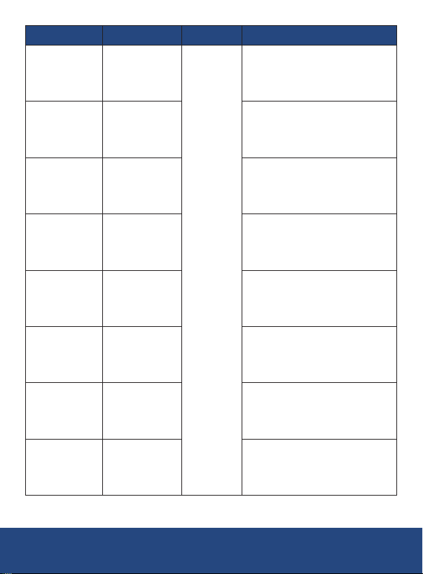
Thermocouple
Type K
Type J
Type T
Type N
Type L
Type U
Type XK
Type BP
Range
-148 to 2501.6°F
(-100 to 1372°C)
-76 to 2192°F
(-60 to 1200°C)
-148 to 752°F
(-100 to 400°C)
-328 to 2372°F
(-200 to 1300°C)
-328 to 1652°F
(-200 to 900°C)
-328 to 752°F
(-200 to 400°C)
-328 to 1472°F
(-200 to 800°C)
32 to 4532°F
(0 to 2500°C)
Resolution
0.1°F/°C
Accuracy
-148 to 32°F (-100 to 0°C):
±2.16°F (±1.2°C)
32 to 2501.6°F (0 to 1372°C):
±1.44°F (±0.8°C)
-76 to 32°F (-60 to 0°C):
±1.8°F (±1°C)
32 to 2192°F (0 to 1200°C):
±1.26°F (±0.7°C)
-148 to 32°F (-100 to 0°C):
±1.8°F (±1°C)
32 to 752°F (0 to 400°C):
±1.26°F (±0.7°C)
-328 to 32°F (-200 to 0°C):
±2.7°F (±1.5°C)
32 to 2372°F (0 to 1300°C):
±1.62°F (±0.9°C)
-328 to 32°F (-200 to 0°C):
±1.53°F (±0.85°C)
32 to 1652°F (0 to 900°C):
±1.26°F (±0.7°C)
-328 to 32°F (-200 to 0°C):
±1.98°F (±1.1°C)
32 to 752°F (0 to 400°C):
±1.35°F (±0.75°C)
-328 to -148°F (-200 to -100°C):
±0.9°F (±0.5°C)
-148 to 1472°F (-100 to 800°C):
±1.08°F (±0.6°C)
32 to 1472°F (0 to 800°C):
±2.16°F (±1.2°C)
1472 to 4532°F (800 to 2500°C):
±4.5°F (±2.5°C)
continued...
REED Instruments
7
1-877-849-2127 | [email protected] | www.reedinstruments.com
Page 8
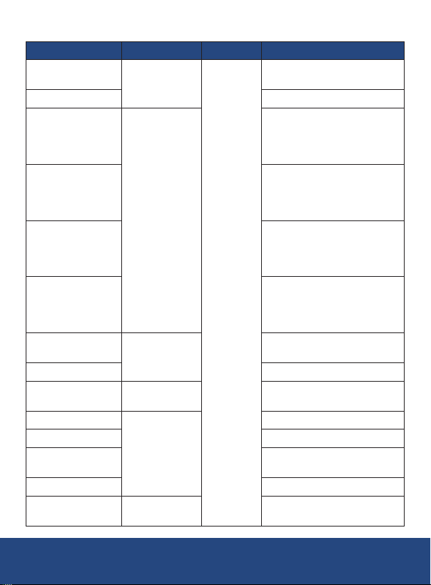
RTDs
RTD Range
Pt100
(2-wire/3-wire)
Pt100 (4-wire) ±0.54°F (±0.3°C)
Pt200
(2-wire/3-wire)
Pt200 (4-wire)
Pt500
(2-wire/3-wire)
Pt500 (4-wire)
Pt1000
(2-wire/3-wire)
Pt1000 (4-wire) ±0.27°F (±0.15°C)
Cu10
Cu50 (2-wire/3-wire)
Cu50 (4-wire) ±0.9°F (±0.5°C)
Cu100
(2-wire/3-wire)
Cu100 (4-wire) ±0.45°F (±0.25°C)
Pt100-392
(2-wire/3-wire)
-328 to 1562°F
(-200 to 850°C)
-328 to 1166°F
(-200 to 630°C)
-328 to 1202°F
(-200 to 650°C)
-148 to 500°F
(-100 to 260°C)
-58 to 302°F
(-50 to 150°C)
-328 to 1166°F
(-200 to 630°C)
REED Instruments
1-877-849-2127 | [email protected] | www.reedinstruments.com
Resolution
0.1°F/°C
Accuracy
±0.72°F (±0.4°C)
-328 to 482°F (-200 to 250°C):
±0.54°F (±0.3°C)
482 to 1166°F (250 to 630°C):
±2.88°F (±1.6°C)
-328 to 482°F (-200 to 250°C):
±0.36°F (±0.2°C)
482 to 1166°F (250 to 630°C):
±1.44°F (±0.8°C)
-328 to 932°F (-200 to 500°C):
±1.08°F (±0.6°C)
932 to 1166°F (500 to 630°C):
±1.62°F (±0.9°C)
-328 to 932°F (-200 to 500°C):
±0.54°F (±0.3°C)
932 to 1166°F (500 to 630°C):
±0.72°F (±0.4°C)
±0.54°F (±0.3°C)
±3.24°F (±1.8°C)
±1.44°F (±0.8°C)
±0.72°F (±0.4°C)
±0.9°F (±0.5°C)
continued...
8
Page 9
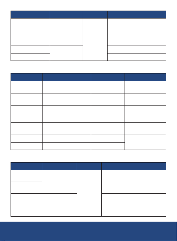
RTD Range
Pt100-392 (4-wire)
Pt100-JIS
(2-wire/3-wire)
Pt100-JIS (4-wire) ±0.54°F (±0.3°C)
Ni120 (2-wire/3-wire)
Ni120 (4-wire) ±0.36°F (±0.2°C)
-328 to 1166°F
(-200 to 630°C)
-112 to 500°F
(-80 to 260°C)
Resolution
0.1°F/°C
Accuracy
±0.54°F (±0.3°C)
±0.9°F (±0.5°C)
±0.54°F (±0.3°C)
Source Function
Function Range Resolution Accuracy
DC Voltage 100mV, 1, 10V
DC Current
Resistance 400, 4000Ω, 40kΩ 0.01, 0.1, 1Ω
Frequency
Pulse 100Hz, 1, 10kHz 1 cyc
Switch Quantity
20mA at 0 to 24mA
20mA (SIM) at 0 to 24mA
200, 2000Hz, 20, 100kHz 0.01, 0.1, 1, 10Hz
100Hz, 1, 10, 100kHz
0.001, 0.01mV,
0.0001V
0.001mA ±(0.02% +2)
0.01, 0.1, 1, 10Hz
±(0.02% +10)
±(0.02% +8)
±(0.05% +10)
±(0.1% +40)
±(0.01% +1) (±3 dgt.),
100kHz: ±5 dgt.
±2 dgt.
Thermocouples
Thermocouple
Type R
Type S
Type B
1-877-849-2127 | [email protected] | www.reedinstruments.com
Range
32 to 3212.6°F
(0 to 1767°C)
1112 to 3308°F
(600 to 1820°C)
Resolution
1°F/°C
REED Instruments
Accuracy
32 to 212°F (0 to 100°C):
±2.7°F (±1.5°C)
212 to 3212.6°F (100 to 1767°C):
±2.16°F (±1.2°C)
1112 to 1472°F (600 to 800°C):
±2.7°F (±1.5°C)
1472 to 3308°F (800 to 1820°C):
±1.98°F (±1.1°C)
continued...
9
Page 10
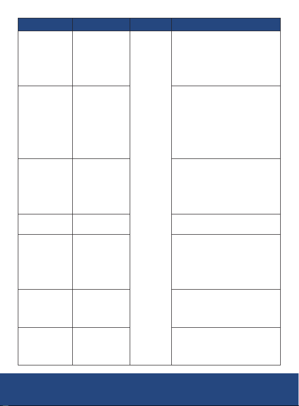
Thermocouple
Type E
Type K
Type J
Type T
Type N
Type L
Type U
Range
-328 to 1832°F
(-200 to 1000°C)
-328 to 2501.6°F
(-200 to 1372°C)
-328 to 2192°F
(-200 to 1200°C)
-418 to 752°F
(-250 to 400°C)
-328 to 2372°F
(-200 to 1300°C)
-328 to 1652°F
(-200 to 900°C)
-328 to 752°F
(-200 to 400°C)
Resolution
0.1°F/°C
REED Instruments
Accuracy
-328 to -148°F (-200 to -100°C):
±1.08°F (±0.6°C)
-148 to 1112°F (-100 to 600°C):
±0.9°F (±0.5°C)
1112 to 1832°F (600 to 1000°C):
±0.72°F (±0.4°C)
-328 to -148°F (-200 to -100°C):
±1.08°F (±0.6°C)
-148 to 752°F (-100 to 400°C):
±0.9°F (±0.5°C)
752 to 2192°F (400 to 1200°C):
±1.26°F (±0.7°C)
2192 to 2501.6°F (1200 to 1372°C):
±1.62°F (±0.9°C)
-200 to -148°F (-200 to -100°C):
±1.08°F (±0.6°C)
-148 to 1472°F (-100 to 800°C):
±0.9°F (±0.5°C)
1472 to 2192°F (800 to 1200°C):
±1.26°F (±0.7°C)
±1.08°F (±0.6°C)
-328 to -148°F (-200 to -100°C):
±1.8°F (±1°C)
-148 to 1652°F (-100 to 900°C):
±1.26°F (±0.7°C)
1652 to 2372°F (900 to 1300°C):
±1.44°F (±0.8°C)
-328 to 32°F (-200 to 0°C):
±1.53°F (±0.85°C)
32 to 1652°F (0 to 900°C):
±1.26°F (±0.7°C)
-328 to 32°F (-200 to 0°C):
±1.98°F (±1.1°C)
32 to 752°F (0 to 400°C):
±1.35°F (±0.75°C)
continued...
10
1-877-849-2127 | [email protected] | www.reedinstruments.com
Page 11
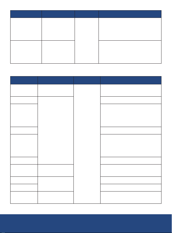
Thermocouple
Type XK
Type BP
Range
-328 to 1472°F
(-200 to 800°C)
32 to 4532°F
(0 to 2500°C)
Resolution
0.1°F/°C
Accuracy
-328 to -148°F (-200 to -100°C):
±0.9°F (±0.5°C)
-148 to 1472°F (-100 to 800°C):
±1.08°F (±0.6°C)
32 to 1472°F (0 to 800°C):
±2.16°F (±1.2°C)
1472 to 4532°F (800 to 2500°C):
±4.5°F (±2.5°C)
RTDs
RTD Range Resolution Accuracy
Pt100-385
Pt100-392
Pt200-385
Pt100-JIS ±0.54°F (±0.3°C)
Pt500-385
Pt1000-385 ±0.36°F (±0.2°C)
Cu10
Cu50
Cu100 ±0.45°F (±0.25°C)
Ni120
-328 to 1472°F
(-200 to 800°C)
-328 to 1166°F
(-200 to 630°C)
-148 to 500°F
(-100 to 260°C)
-58 to 302°F
(-50 to 150°C)
-112 to 500°F
(-80 to 260°C)
0.1°F/°C
±0.6°F (±0.33°C)
±0.54°F (±0.3°C)
-328 to 482°F (-200 to 250°C):
±0.36°F (±0.2°C)
482 to 1166°F (250 to 630°C):
±1.44°F (±0.8°C)
-328 to 932°F (-200 to 500°C):
±0.54°F (±0.3°C)
932 to 1166°F (500 to 630°C):
±0.72°F (±0.4°C)
±3.24°F (±1.8°C)
±0.9°F (±0.5°C)
±0.36°F (±0.2°C)
continued...
REED Instruments
11
1-877-849-2127 | [email protected] | www.reedinstruments.com
Page 12

Function Specifications
Ramp Functions: Source functions: Voltage, Current,
Resistance, Frequency, Temperature
Loop Power Function: Voltage: 24V
Accuracy: 10%
Maximum current: 22mA,
short circuit protected
Step Functions: Source functions: Voltage, Current,
Resistance, Frequency, Temperature
Steps: 25% of range, 100% of range
Ramps: Slow ramp, fast ramp, 25% step-ramp
General Specifications
Display: 20,000 count TFT color LCD display
Kick Stand: Yes
Power Supply: 1.2V x 6 AA rechargeable batteries
Auto shut-off: Yes
Low Battery Indicator: Yes
Replaceable Test Leads: Yes
Product Certications: CE, RoHS
Operating Temperature: 14 to 131°F (-10 to 55°C)
Operating Humidity Range: ≤95%
Storage Temperature: -4 to 158°F (-20 to 70°C)
Max Operating Altitude: 6561' (2000m)
Dimensions: 7.7 x 3.7 x 2.3" (195 x 95 x 58mm)
Weight: 22.92oz (650g)
1-877-849-2127 | [email protected] | www.reedinstruments.com
REED Instruments
12
Page 13
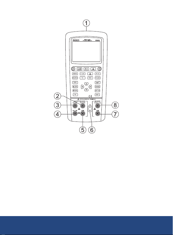
Instrument Description
1. USB-C charging, communication and pressure module terminal
2 + 5. Terminals for measurement/output of V, mV, Hz, Ω, RTD
3 + 4. Terminals for 3/4-wire measurement of current output
and resistance/RTD
4 + 5. Terminals for current measurement or SIM output
6. TC measurement/output terminal
7 + 8. Function terminals for the measurement of isolated module in
upper screen
continued...
1-877-849-2127 | [email protected] | www.reedinstruments.com
REED Instruments
13
Page 14
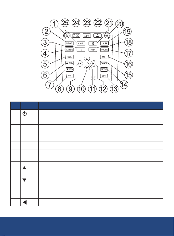
Buttons
No. Symbol Description
1
2 MEAS Switch the function of lower screen to measurement mode.
3 TC
4 SOURCE Switch the functions of lower screen to output mode.
5 100%
6
7
8 0%
9
Power ON/OFF
Select measurement or output function of TC in lower screen.
Continuously press this button to switch between different
thermocouple types.
When the lower screen is in output mode, press to recall and output
100% value of the preset range. Hold to reset the 100% value.
When the lower screen is in output mode, press to increase output
25%
by 25% of preset range.
When the lower screen is in output mode, press to decrease output
25%
by 25% of preset range.
When the lower screen is in output mode, press to recall and
output 0% value of the preset range. Hold to reset the 0% value.
LEFT Button, used to enable the pulse output function.
continued...
REED Instruments
14
1-877-849-2127 | [email protected] | www.reedinstruments.com
Page 15
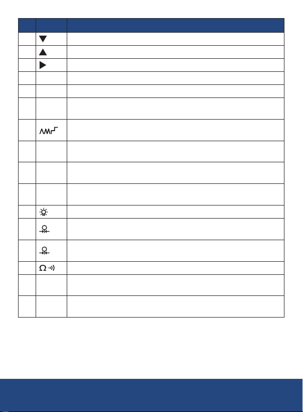
No. Symbol Description
10
11
12
13 ESC Exit button
14 SETUP Setup button, hold to enter the setup interface of system parameter.
15 RANGE
16
17 PULSE
18 RTD
19 Hz Ω
20
21
22
23 Select resistance in upper screen, continuity measurement.
V mA
24
Loop
25 V mA
DOWN Button
UP Button, used to revise the output value.
RIGHT Button
When the lower screen is in output mode, continuously press to
switch the range for current range.
When the lower screen is in output mode, press to enable ramping
output function.
Select pulse in lower screen, measurement/output function of
switch quantity.
Select measurement/output function of RTD in lower screen.
Continuously press to switch between different RTD graduations.
Select frequency in lower screen, resistance measurement/
output function.
Adjust screen brightness.
Select pressure measurement/output function in lower screen.
Continuously press to switch between different pressure units.
Select pressure measurement/output function in upper screen.
Continuously press to switch between different pressure units.
Select measurement function of millivolt, voltage, milliamp, loop
current and others in upper screen.
Select measurement/output function of millivolt, voltage, milliamp,
SIM and others in lower screen.
1-877-849-2127 | [email protected] | www.reedinstruments.com
REED Instruments
15
Page 16
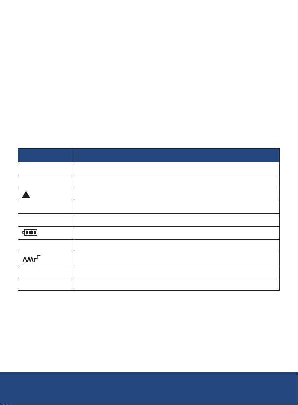
Display Description
Symbol Description
SOURCE Source Output Mode
MESURE Measurement Mode
Data Adjustment
SIM Transmitter Output Simulation
LOOP Loop Measurement
Battery Level
LOAD Overload
Ramp/Step Output
PC Remote Control
APO Auto Power Off
1-877-849-2127 | [email protected] | www.reedinstruments.com
REED Instruments
16
Page 17
Operating Instructions
Power ON/OFF
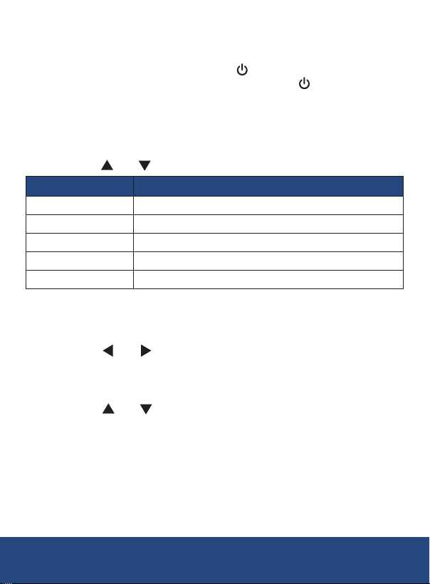
To turn the meter ON, press and hold the button for approximately
4 seconds. To turn the meter OFF, press and hold the button for
2 seconds.
Setup Mode
1. When the meter is powered ON, press and hold the SETUP button
for 2 seconds to enter the Setup Mode.
2.
Press the and buttons to scroll through the following parameters.
Parameter Description
Auto Power Off Set Auto Power Off
Brightness Adjust the LCD brightness level
Temperature Unit Select the temperature unit of measure
Remote Control Enable/Disable remote control commands
Beep Control Enable/Disable the beeper
3. Once the appropriate parameter has been highlighted, follow the
instructions below.
Set Auto Power Off
1. Press the and buttons to set the auto power off timer between
1 and 60 minutes. To disable the auto power off function, set the
timer to "0".
Note: The default auto power off time is set to 30 minutes.
2. Press the
applicable parameter.
Note: At any time, press the ESC button to exit the setup mode and
resume normal operation.
and
buttons to conrm selection and skip to the next
continued...
1-877-849-2127 | [email protected] | www.reedinstruments.com
REED Instruments
17
Page 18
Adjust the LCD Brightness Level
1. Press the and buttons to set the display's brightness level
between 10 and 100%.
Brightness level can also be adjusted in 10, 25, 50, 75 and 100%
2. Press the
Note: At any time, press the ESC button to exit the setup mode and
resume normal operation.
increments by simply pressing the button.
and
applicable parameter.
buttons to conrm selection and skip to the next
Select the Temperature Unit of Measure
1. Press the and buttons to select between °F and °C.
2. Press the
applicable parameter.
Note: At any time, press the ESC button to exit the setup mode and
resume normal operation.
and
buttons to conrm selection and skip to the next
Enable/Disable Remote Control Commands
1. Press the and buttons to select between ON (enabled) or
OFF (disabled). (See the Remote Control Commands section for
additional details.)
2. Press the
applicable parameter.
Note: At any time, press the ESC button to exit the setup mode and
resume normal operation.
and
buttons to conrm selection and skip to the next
Enable/Disable the Beeper
1. Press the and buttons to select between ON (enabled) or
OFF (disabled).
2. Press the
applicable parameter.
Note: At any time, press the ESC button to exit the setup mode and
resume normal operation.
and
buttons to conrm selection and skip to the next
1-877-849-2127 | [email protected] | www.reedinstruments.com
REED Instruments
18
Page 19
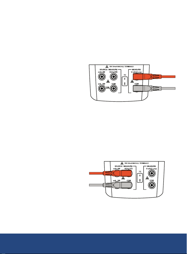
Measurement Modes
Millivolt Measurement (Upper Display)
1. Press the V mA LOOP button to select millivolt measurement.
LOOP should not be activated.
2. Connect the leads as shown below and connect the tips to the
equipment being tested.
3. The LCD will display the reading.
Millivolt Measurement (Lower Display)
1. If the meter is in output mode (SOURCE), press the MEAS button to
switch to measurement mode.
2. Press the V mA button to select millivolt measurement.
3. Connect the leads as shown below and connect the tips to the
equipment being tested.
4. The LCD will display the reading.
continued...
1-877-849-2127 | [email protected] | www.reedinstruments.com
REED Instruments
19
Page 20
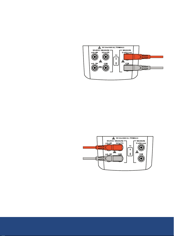
Voltage Measurement (Upper Display)
1. Press the V mA LOOP button to select voltage measurement.
2. Connect the leads as shown below and connect the tips to the
equipment being tested.
3. The LCD will display the reading.
Voltage Measurement (Lower Display)
1. If the meter is in output mode (SOURCE), press the MEAS button to
switch to measurement mode.
2. Press the V mA button to select voltage measurement.
3. Connect the leads as shown below and connect the tips to the
equipment being tested.
4. The LCD will display the reading.
continued...
1-877-849-2127 | [email protected] | www.reedinstruments.com
REED Instruments
20
Page 21
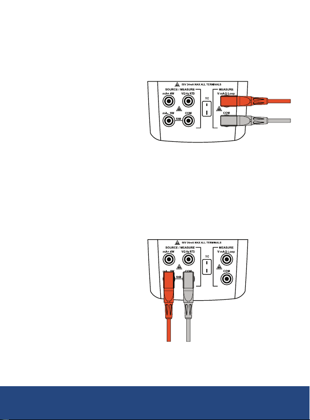
MilliAmp Measurement (Upper Display)
1. Press the V mA LOOP button to select milliamp measurement.
2. Connect the leads as shown below and connect the tips to the
equipment being tested.
3. The LCD will display the reading.
MilliAmp Measurement (Lower Display)
1. If the meter is in output mode (SOURCE), press the MEAS button to
switch to measurement mode.
2. Press the V mA button to select milliamp measurement.
3. Connect the leads as shown below and connect the tips to the
equipment being tested.
4. The LCD will display the reading.
continued...
1-877-849-2127 | [email protected] | www.reedinstruments.com
REED Instruments
21
Page 22
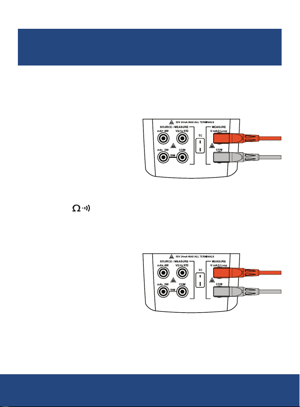
Current Measurement with Loop Power (Upper Display)
The loop power function activates a 24V supply in series with the
current measuring circuit, allowing users to test a transmitter
1. Press the V mA LOOP button to select loop measurement.
2. Connect the leads as shown below and connect the tips to the
equipment being tested.
3. The LCD will display the reading.
when it is disconnected from plant wiring.
Resistance Measurement (Upper Display)
1. Press the button to select resistance measurement (Ω).
2. Connect the leads as shown below and connect the tips to the
equipment being tested.
3. The LCD will display the reading.
continued...
1-877-849-2127 | [email protected] | www.reedinstruments.com
REED Instruments
22
Page 23
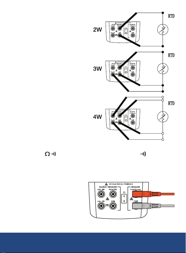
Resistance Measurement
(Lower Display)
1. If the meter is in output
mode (SOURCE), press the
MEAS button to switch to
measurement mode.
2. Press the Hz Ω button
to select 2, 3 or 4-wire
resistance measurement.
3. Lower display resistance
measurement supports the
following 2, 3 or 4-wire
connections.
Continuity Measurement (Upper Display)
1. Press the button until continuity measurement ( ) is selected.
2. Connect the leads as shown below and connect the tips to the
equipment being tested.
3. The LCD will display the reading.
continued...
1-877-849-2127 | [email protected] | www.reedinstruments.com
REED Instruments
23
Page 24
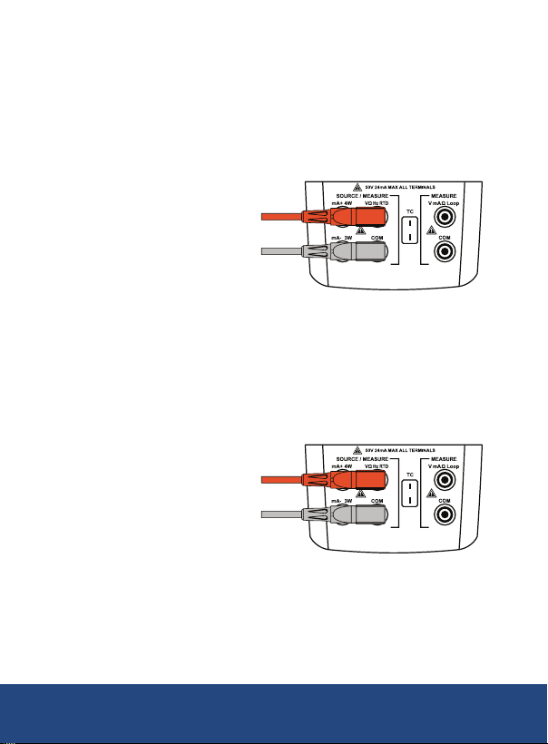
Frequency Measurement (Lower Display)
1. If the meter is in output mode (SOURCE), press the MEAS button to
switch to measurement mode.
2. Press the Hz Ω button to select frequency measurement (Hz).
3. Connect the leads as shown below and connect the tips to the
equipment being tested.
4. The LCD will display the reading.
Pulse Measurement (Lower Display)
1. If the meter is in output mode (SOURCE), press the MEAS button to
switch to measurement mode.
2. Press the PULSE button to select pulse measurement.
3. Connect the leads as shown below and connect the tips to the
equipment being tested.
4. Press the SETUP button to start/stop pulse measurement.
5. When done, press the ESC button to reset/clear the current
pulse count.
continued...
1-877-849-2127 | [email protected] | www.reedinstruments.com
REED Instruments
24
Page 25
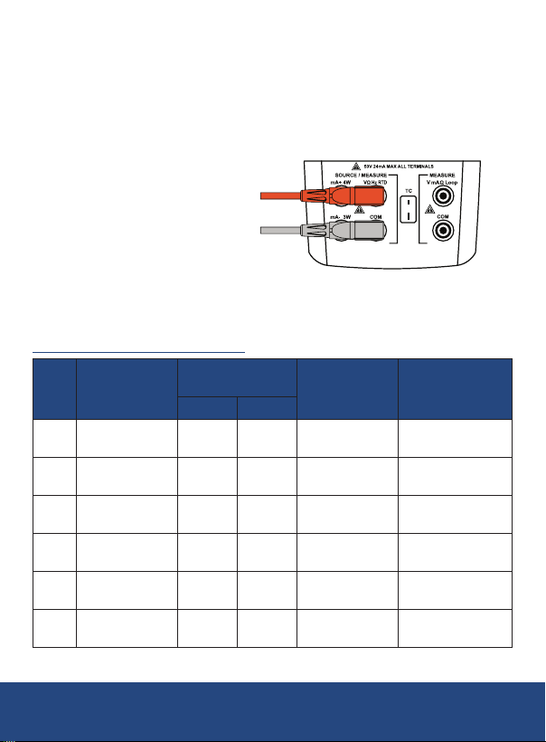
Switch Quantity Measurement (Lower Display)
1. If the meter is in output mode (SOURCE), press the MEAS button to
switch to measurement mode.
2. Press the PULSE button to select switch quantity measurement.
3. Connect the leads as shown below and connect the tips to the
equipment being tested.
Note: Minimum duration for an open/close test is 500ms.
Thermocouple Measurement (Lower Display)
Thermocouple Types Accepted
Positive Lead
Type
Material
E Chromel Purple Violet Constantan
N Ni-Cr-Si Orange Pink Ni-Si-Mg
J Iron White Black Constantan
K Chromel Yellow Green Alumel
T Copper Blue Brown Constantan
Platinum
B
(30% Rhodium)
Positive Lead (H)
Color
ANSI* IEC**
Gray
Negative Lead
Material
Platinum
(6% Rhodium)
Specified Range
-328 to 1742°F
(-200 to 950°C)
-328 to 2372°F
(-200 to 1300°C)
-328 to 2192°F
(-200 to 1200°C)
-328 to 2498°F
(-200 to 1370°C)
-328 to 752°F
(-200 to 400°C)
1112 to 3272°F
(600 to 1800°C)
continued...
REED Instruments
25
1-877-849-2127 | [email protected] | www.reedinstruments.com
Page 26
Positive Lead
Type
Material
Platinum
R
(13% Rhodium)
Platinum
S
(10% Rhodium)
L Iron
U Copper
*American National Standards Institute (ANSI) device negative lead (L) is always red.
**International Electrotechnical Commission (IEC) device negative lead (L) is always white.
Positive Lead (H)
Color
ANSI* IEC**
Black Orange Platinum
Negative Lead
Material
Constantan
Specified Range
-4 to 3182°F
(-20 to 1750°C)
-328 to 1652°F
(-200 to 900°C)
-328 to 752°F
(-200 to 400°C)
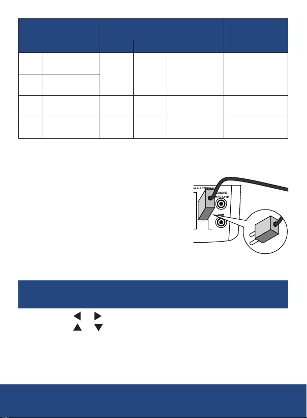
1. If the meter is in output mode (SOURCE), press the MEAS button to
switch to measurement mode.
2. Press the TC button to select between
R, S, K, E, J, T, N, B, L, U, XK and BP
thermocouple measurement.
3. Connect the appropriate TC miniplug to
the TC input/output terminal as shown
on the right.
4. The LCD will display the reading.
5. If required, a user can manually adjust the cold junction
compensation for thermocouples by pressing the SETUP button.
Note: To revert back to automatic cold junction compensation,
press the SETUP button followed by the ESC button.
6. Press the or buttons to toggle through the adjustable values.
7. Press the
or buttons to adjust the activated value.
8. Press the SETUP button to conrm selection and resume
normal operation.
continued...
REED Instruments
26
1-877-849-2127 | [email protected] | www.reedinstruments.com
Page 27
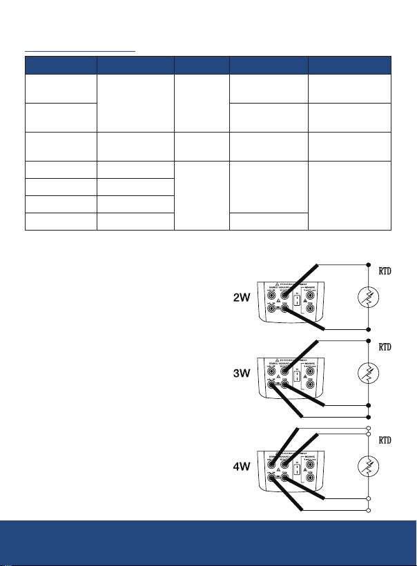
RTD Measurement
RTD Types Accepted
RTD Type
Pt100 (3926)
Pt100 (385) 0.00385Ω/°C
Ni120 (672) 120Ω Nickel 0.00672Ω/°C
Pt200 (385) 200Ω
Pt500 (385) 500Ω
Pt1000 (385) 1000Ω
Pt100 (3916) 100Ω 0.003916Ω/°C
The Pt100 commonly used in U.S. industrial applications is Pt100 (3916), α=0.003916Ω/°C.
(Also designated as JIS curve.) The IEG standard RTD is the Pt100 (385), α=0.00385Ω/°C.
Ice Point (R
100Ω Platinum
θ
)
Material
Platinum
1. If the meter is in output mode
(SOURCE), press the MEAS button
to switch to measurement mode.
2. Press the RTD button to select
between Pt100-385, Pt100-392,
Pt100-JIS, Pt200, Pt500, Pt1000,
Cu10, Cu50, Cu100 and Ni120
RTD measurement.
3. Connect the leads as shown on
the right and connect the tips to
the equipment being tested.
4. Press the SETUP button to
toggle between 2, 3 or 4-wire
connections.
5. Connect the RTD to the
appropriate 2, 3 or 4-wire
input terminals.
6. The LCD will display the reading.
α
0.003926Ω/°C
0.00385Ω/°C
Range
-328 to 1166°F
(-200 to 630°C)
-328 to 1472°F
(-200 to 800°C)
-112 to 500°F
(-80 to 260°C)
-328 to 1166°F
(-200 to 630°C)
REED Instruments
27
1-877-849-2127 | [email protected] | www.reedinstruments.com
Page 28
Source Modes (Lower Display)
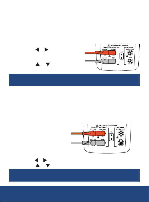
Millivolt Output
1. If the meter is in measurement mode (MEASURE), press the
SOURCE button to switch to source mode.
2. Press the V mA button to select millivolt output.
3. Connect the leads as shown below and connect the tips to the
equipment being tested.
4. Press the
toggle through the adjustable
output values.
5. Press the
the activated output value.
Note: The meter outputs the corresponding millivolt value
Voltage Output
1. If the meter is in measurement mode (MEASURE), press the
SOURCE button to switch to source mode.
2. Press the V mA button to select voltage output.
3. Connect the leads as shown below and connect the tips to the
equipment being tested.
or buttons to
or buttons to adjust
in real time whenever the output value is changed.
4.
Press the or buttons to toggle through the adjustable output values.
5. Press the or buttons to adjust the activated output value.
Note: The meter outputs the corresponding voltage value
in real time whenever the output value is changed.
REED Instruments
1-877-849-2127 | [email protected] | www.reedinstruments.com
continued...
28
Page 29
Sourcing 4 to 20mA
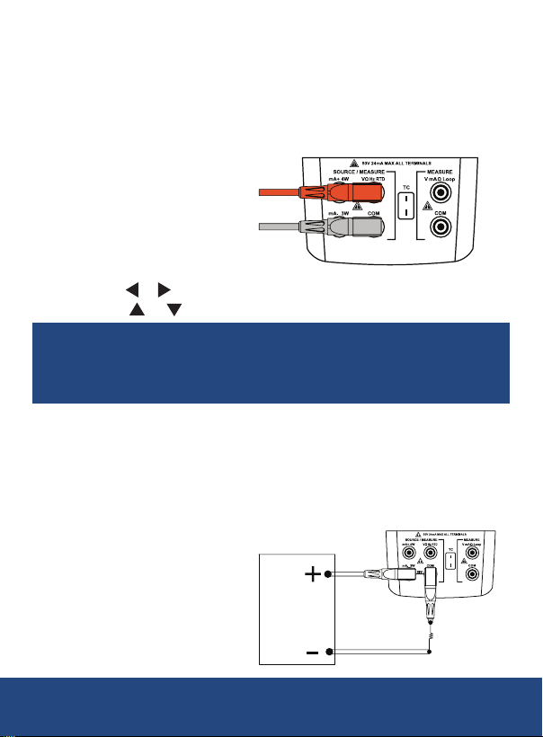
1. If the meter is in measurement mode (MEASURE), press the
SOURCE button to switch to source mode.
2. Press the V mA button to select milliamp output.
3. Connect the leads as shown below and connect the tips to the
equipment being tested.
4.
Press the or buttons to toggle through the adjustable output values.
5. Press the or buttons to adjust the activated output value.
Note: The meter outputs the corresponding milliamp
value in real time whenever the output value is changed.
If the output load is too high, the output value will
flash and "LOAD" will appear on the LCD screen.
Simulating a 4 to 20mA Transmitter
1. If the meter is in measurement mode (MEASURE), press the
SOURCE button to switch to source mode.
2. Press the V mA button to select simulator mode.
3. Connect the leads as shown below and connect the tips to the
equipment being tested.
continued...
1-877-849-2127 | [email protected] | www.reedinstruments.com
REED Instruments
29
Page 30
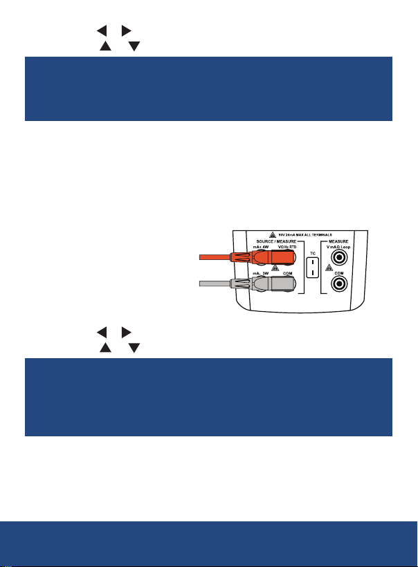
4.
Press the or buttons to toggle through the adjustable output values.
5. Press the or buttons to adjust the activated output value.
Note: The meter outputs the corresponding milliamp
value in real time whenever the output value is changed.
If the output load is too high, the output value will
flash and "LOAD" will appear on the LCD screen.
Resistance Output
1. If the meter is in measurement mode (MEASURE), press the
SOURCE button to switch to source mode.
2. Press the Hz Ω button to select resistance output.
3. Connect the leads as shown below and connect the tips to the
equipment being tested.
4.
Press the or buttons to toggle through the adjustable output values.
5. Press the or buttons to adjust the activated output value.
Note: Excitation current is required for resistance output.
If the meter displays "ExI HI", the excitation current from
the device under test exceeds the limits of the R5850.
If the meter displays "Exl LO", the excitation current from
the device under test is below the limits of the R5850.
continued...
1-877-849-2127 | [email protected] | www.reedinstruments.com
REED Instruments
30
Page 31
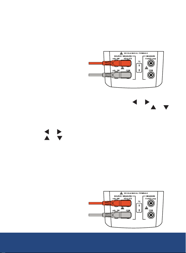
Frequency Output
1. If the meter is in measurement mode (MEASURE), press the
SOURCE button to switch to source mode.
2. Press the Hz Ω button to select frequency output (Hz).
3. Connect the leads as shown below and connect the tips to the
equipment being tested.
Press the RANGE button to select between 110, 200, 2000Hz and 110kHz.
4.
5. To manually adjust the selected ranges, press the or buttons to
toggle through the adjustable output values and press the or
buttons to adjust the activated output value.
6. Press the SETUP button to manually enter the frequency amplitude
(Voltage Peak).
7. Press the or buttons to toggle through the adjustable values.
8. Press the or buttons to adjust the activated value.
9. Press the ESC button to cancel the manual adjustment.
Pulse Output
1. If the meter is in measurement mode (MEASURE), press the
SOURCE button to switch to source mode.
2. Press the PULSE button to select pulse output.
3. Connect the leads as shown below and connect the tips to the
equipment being tested.
continued...
1-877-849-2127 | [email protected] | www.reedinstruments.com
REED Instruments
31
Page 32
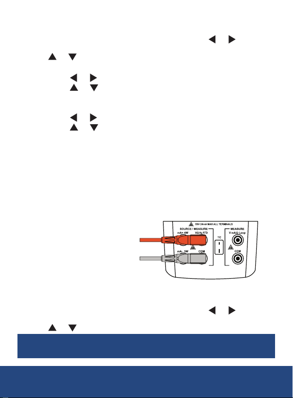
4. Press the RANGE button to select between the default 100Hz,
1 and 10kHz ranges.
5. To manually adjust the selected ranges, press the or buttons
to toggle through the adjustable output values and press
the or buttons to adjust the activated output value.
6. Press the SETUP button to set the number of pulses.
7. Press the or buttons to toggle through the adjustable values.
8. Press the or buttons to adjust the activated value.
9. Press the SETUP button to conrm the selected number of pulses
and to manually enter the frequency amplitude (Voltage Peak).
10. Press the or buttons to toggle through the adjustable values.
11. Press the or buttons to adjust the activated value.
12. Press the SETUP button to conrm selections and start outputting at
the preset frequency and amplitude.
Switch Quantity Output
1. If the meter is in measurement mode (MEASURE), press the
SOURCE button to switch to source mode.
2. Press the PULSE button to select switch quantity output.
3. Connect the leads as shown below and connect the tips to the
equipment being tested.
4. Press the RANGE button to select between the default 100Hz,
1 and 10kHz ranges.
5. To manually adjust the selected ranges, press the or buttons
to toggle through the adjustable output values and press
the or buttons to adjust the activated output value.
Note: The meter outputs the corresponding frequency value
in real time whenever the output value is changed.
REED Instruments
1-877-849-2127 | [email protected] | www.reedinstruments.com
continued...
32
Page 33
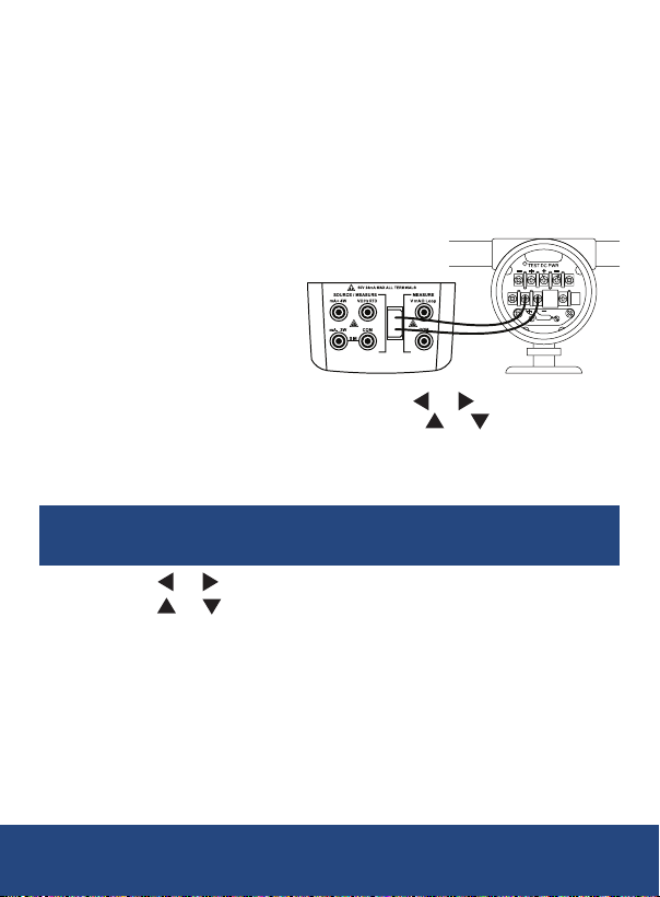
Thermocouple Output
The meter supports simulating temperature output of following
thermocouples: R, S, K, E, J, T, N, B, L, U, XK and BP.
1. If the meter is in measurement mode (MEASURE), press the
SOURCE button to switch to source mode.
2. Press the TC button to select the applicable thermocouple output.
3. Connect the appropriate TC miniplug to the TC input/output terminal
and connect the tips to the equipment being tested as shown below.
4. To set the required output value, press the or buttons to toggle
through the adjustable values and press the or buttons to
adjust the activated value.
5. If required, a user can manually adjust the cold junction
compensation for thermocouples by pressing the SETUP button.
Note: To revert back to automatic cold junction compensation,
press the SETUP button followed by the ESC button.
6. Press the or buttons to toggle through the adjustable values.
7. Press the or buttons to adjust the activated value.
8. Press the SETUP button to conrm selection and resume
normal operation.
continued...
1-877-849-2127 | [email protected] | www.reedinstruments.com
REED Instruments
33
Page 34
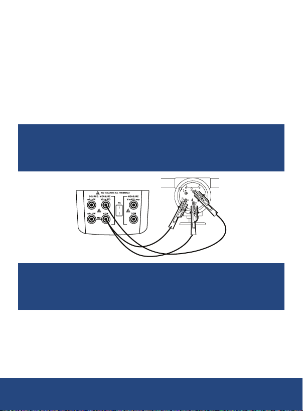
RTD Output
1. If the meter is in measurement mode (MEASURE), press
the SOURCE button to switch to source mode.
2. Press the RTD button to select between
Pt100-385, Pt100-392, Pt100-JIS, Pt200,
Pt500, Pt1000, Cu10, Cu50, Cu100 and
Ni120 RTD output.
3. Connect the RTD to the appropriate 2-wire
input terminals and connect the tips to the
equipment being tested as shown below.
Note: Use the 3W and 4W terminals for measurement only,
not for simulation. The calibrator simulates a 2-wire RTD at its
front panel. To connect to a 3-wire or 4-wire transmitter, use
the stacking cables to provide the extra wires as shown below.
Note: If the meter displays "ExI HI", the excitation current
from the device under test exceeds the limits of the R5850.
If the meter displays "Exl LO", the excitation current from
the device under test is below the limits of the R5850.
continued...
1-877-849-2127 | [email protected] | www.reedinstruments.com
REED Instruments
34
Page 35
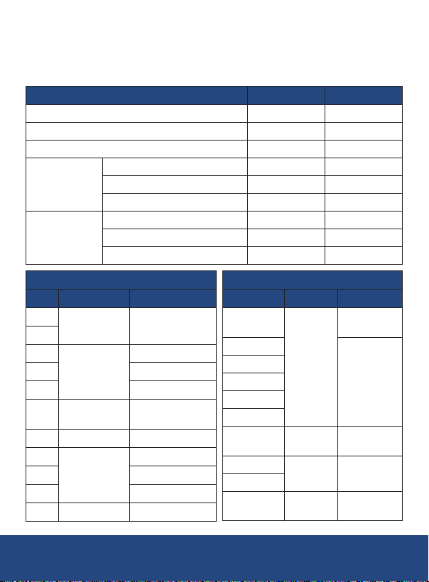
Stepping the Output
Stepping operation and percentage display can be used after the values
of 0% and 100% are set. Some values of the meter have been set by
default and are listed below.
Output Function 0% Value 100% Value
Voltage 0V 10V
Millivolt 0mV 100mV
Current 4mA 20mA
400Ω 0Ω 400Ω
Resistance
Frequency
4000Ω 0Ω 4000Ω
40KΩ 0Ω 40,000Ω
200Hz 0Hz 200Hz
2000Hz 200Hz 2000Hz
20kHz 2kHz 20kHz
Thermocouples
Type
0% Value 100% Value
R
32°F (0°C)
S
K
-328°F
E 1832°F (1000°C)
(-200°C)
J 2192°F (1200°C)
-418°F
T
(-250°C)
1112°F (600°C)
B
L
-328°F
U 752°F (400°C)
(-200°C)
XK 1472°F (800°C)
BP 32°F (0°C) 4532°F (2500°C)
3212.6°F (1767°C)
2501.6°F (1372°C)
752°F (400°C)
3308°F (1820°C)
1652°F (900°C)
REED Instruments
Type 0% Value 100% Value
Pt100-385
Pt100-392
Pt200-385
Pt100-JIS
Pt500-385
Pt1000-385
Cu10
Cu50
Cu100
Ni120
RTDs
-328°F
(-200°C)
-148°F
(-100°C)
-58°F
(-50°C)
-112°F
(-80°C)
1562°F
(850°C)
1166°F
(630°C)
500°F
(260°C)
302°F
(150°C)
500°F
(260°C)
continued...
35
1-877-849-2127 | [email protected] | www.reedinstruments.com
Page 36
1. While the meter is in output mode, press the 0%, 100%, 25%
or 25% buttons to quickly output the value of the corresponding
percentage of the current output function.
2. To manually set the output value of the corresponding percentage
for both 0% and 100%, press the or buttons to toggle through
the adjustable values and press the or buttons to adjust the
activated value.
3. Press and hold the applicable percentage button until the buzzer
beeps to save the current output value as the new 0% or 100% value.
Note:
• 100% value must be greater than 0% value.
• Use the
in 25% increments.
25% or 25% buttons to step the output value up or down
Auto Ramping the Output
Auto ramping while in the applicable output function highlighted above, gives
the ability to continuously apply a varying stimulus from the calibrator to a
transmitter, while hands remain free to test the response of the transmitter.
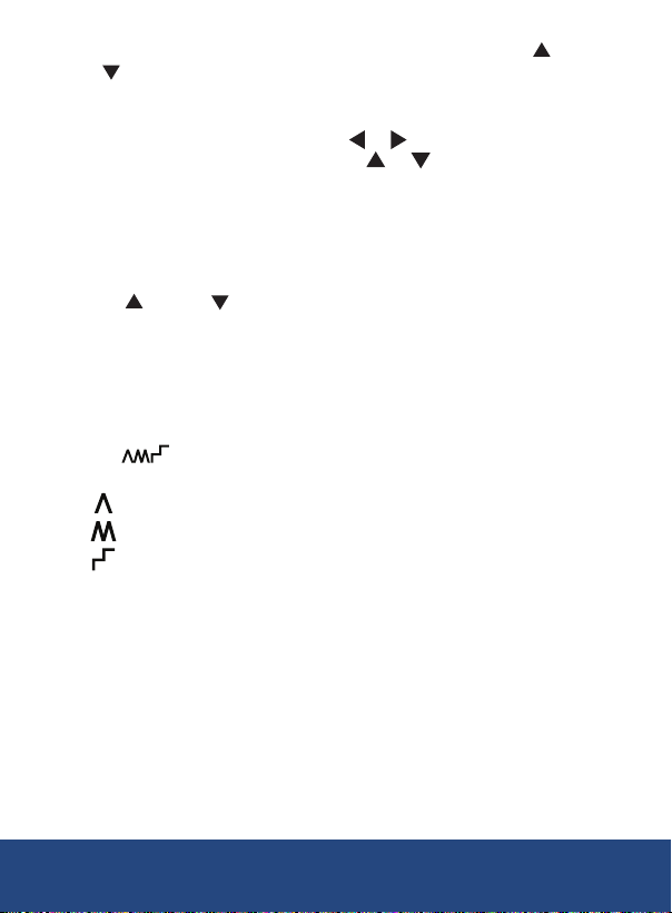
When the button is pressed, the calibrator produces a continuously
repeating 0% to 100% to 0% ramp in one of three ramp waveforms:
45 second smooth ramp
20 second smooth ramp
25% step ramp, pausing for 5 seconds at each step
Note: Press any key to exit the ramping output function.
Remote Control Commands
The R5850 offers the ability to control the calibrator remotely from a PC
running a terminal emulator program. The remote control commands give
access to all capabilities of the calibrator with the exception of pressure
measurement. (See the Enable/Disable Remote Control Commands section
for additional details.) The calibrator will initialize with its remote port enabled.
The baud rate of the serial port is 115,200bps. The communication protocol
sheet is available for download by visiting www.REEDInstruments.com.
1-877-849-2127 | [email protected] | www.reedinstruments.com
REED Instruments
36
Page 37

Charging the Battery
1. Connect the R5850 into a wall outlet using the included wall charger
with USB-C cable to charge the Ni-MH battery.
2. Charge the meter until the battery indicator appears full and remove
the charging cable when completed.
Applications
• Testing loop-powered isolators and two-wire transmitters.
• Verifying and calibrating processes involving mA instrumentation.
Accessories and Replacement Parts
• TP-01 Type K Beaded Wire Probe
• R1000 Safety Test Lead Set
• R1020 Fused Test Lead Set
• R2950 Type K Immersion Probe
• R2940 Type K Air/Gas Probe
• R2930 Type K Right Angle Surface Probe
• R2920 Type K Surface Probe
• R2960 Type K Needle Tip Probe
• R1050-KIT2 Deluxe Safety Test Lead Kit
• R8888 Medium Hard Carrying Case
Don't see your part listed here? For a complete list of all accessories and
replacement parts visit your product page on www.REEDinstruments.com.
Product Care
To keep your instrument in good working order we recommend the following:
• Store your product in a clean, dry place.
• Charge the battery as needed.
• If your instrument isn't being used for a period of one month or longer
please remove the battery.
• Clean your product and accessories with biodegradable cleaner. Do not
spray the cleaner directly on the instrument. Use on external par ts only.
1-877-849-2127 | [email protected] | www.reedinstruments.com
REED Instruments
37
Page 38
Product Warranty
REED Instruments guarantees this instrument to be free of defects in
material or workmanship for a period of two (2) years from date of shipment.
During the warranty period, REED Instruments will repair or replace, at no
charge, products or parts of a product that proves to be defective because
of improper material or workmanship, under normal use and maintenance.
REED Instruments total liability is limited to repair or replacement of the
product. REED Instruments shall not be liable for damages to goods,
property, or persons due to improper use or through attempts to utilize the
instrument under conditions which exceed the designed capabilities. In
order to begin the warranty service process, please contact us by phone
at 1-877-849-2127 or by email at [email protected] to discuss
the claim and determine the appropriate steps to process the warranty.
Product Disposal and Recycling
Please follow local laws and regulations when disposing or recycling
your instrument. Your product contains electronic components and
must be disposed of separately from standard waste products.
Product Support
If you have any questions on your product, please contact your authorized
REED distributor or REED Instruments Customer Service by phone at
1-877-849-2127 or by email at [email protected].
Please visit www.REEDInstruments.com for the most
up-to-date manuals, datasheets, product guides and software.
Product specifications subject to change without notice.
All rights reserved. Any unauthorized copying or reproduction of this
manual is strictly prohibited without prior written permission from
REED Instruments.
1-877-849-2127 | [email protected] | www.reedinstruments.com
REED Instruments
38
Page 39

TEST & MEASURE
WITH CONFIDENCE
Access our
Product Catalog
Over 200 portable test and
measurement instruments
1-877-849-2127 | [email protected] | www.reedinstruments.com
REED Instruments
Page 40

 Loading...