

Page 1
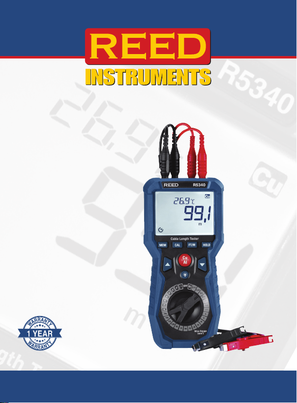
Cable Length
Tester
Instruction
Manual
R5340
1-877-849-2127 | [email protected] | www.reedinstruments.com
REED Instruments
Page 2

Table of Contents
Introduction ................................................................................................ 3
Product Quality .......................................................................................... 3
Safety ......................................................................................................... 3
Features ..................................................................................................3-4
Included ..................................................................................................... 4
Specications .......................................................................................... 4-6
Instrument Description ............................................................................... 7
Display Description .................................................................................... 8
Operating Instructions .......................................................................... 9-18
Power ON/OFF ..................................................................................... 9
Calibration Procedure ....................................................................... 9-11
Measuring the Length of a Cable ...................................................11-12
User-selected Programming Mode ...............................................12-13
The User Selected Mode offers the following functionalities ....12-13
How to Save the Resistance of a Test Cable ................................. 13-14
Measuring Cable Length in User-Defined Mode ...........................14-15
Programmable Switch Positions User’s Table ..................................... 16
Clearing Memory Locations in User-Selected Mode ........................... 16
Measuring Resistance .......................................................................... 17
Data Hold ............................................................................................ 17
Backlight .............................................................................................. 18
Battery Replacement ............................................................................... 18
Applications ............................................................................................. 18
Product Care ............................................................................................ 18
Product Warranty ..................................................................................... 19
Product Disposal and Recycling .............................................................. 19
Product Support ...................................................................................... 19
1-877-849-2127 | [email protected] | www.reedinstruments.com
REED Instruments
2
Page 3

Introduction
Thank you for purchasing your REED R5340 Cable Length Tester. Please
read the following instructions carefully before using your instrument. By
following the steps outlined in this manual your meter will provide years of
reliable service.
Product Quality
This product has been manufactured in an ISO9001 facility and has been
calibrated during the manufacturing process to meet stated
product specications.
Safety
• Do not connect this unit to live voltage.
• Ensure the test leads are removed from the circuit and the unit is
powered off before opening the case.
• Do not expose this meter to rain, moisture, or high humidity.
• Do not operate the meter in extreme temperatures.
• Do not use the meter if it is wet or damaged.
• Always ensure test leads or accessories are clean and dry, and their
insulation is in good condition before use.
• Do not operate the meter with the case open.
• Using the meter near equipment that generates electromagnetic
interference may cause unstable or inaccurate readings.
• Failure to observe these safety instructions can result in serious injury
or death.
• Never attempt to repair or modify your instrument. Dismantling your
product, other than for the purpose of replacing batteries may cause
damage that will not be covered under the manufacturer's warranty.
Servicing should only be provided by an authorized service center.
1-877-849-2127 | [email protected] | www.reedinstruments.com
REED Instruments
3
Page 4

Features
• Measures cable lengths up to 100,000 feet (30km)
•
Resistance measurement ranges of up to 1999.9mΩ
•
20 preset cable sizes and 8 user-dened sizes
•
1999 count backlit LCD display
•
User selectable unit of measure (ft/m)
•
Built-in kickstand
•
Compatible with magnetic hanging strap (sold separately)
•
Overrange indicators
•
Low battery indicator and auto shut-off
Included
• Cable Length Tester
•
Test Leads and Clips
•
Copper Rod
•
Carrying Case
•
Batteries
Specifications
Length Measurement
Range: 1999.9m
19.999, 30.00km
1999.9, 19.999ft
100.00kft
Accuracy: 1999.9m: ±(1.0% rdg. +1m)
19.999: ±(1.0% rdg. +0.05km)
30.00km: ±(1.2% rdg. +0.10km)
1999.9: ±(1.0% rdg. +3ft)
19.999ft: ±(1.0% rdg. +0.16kft)
continued...
1-877-849-2127 | [email protected] | www.reedinstruments.com
REED Instruments
4
Page 5

100.00kft: ±(1.2% rdg. +0.33kft)
Resolution: 0.1, 1m
0.01km
0.1, 1, 0.01ft
Resistance Measurement
Range: 1999.9, 199.99, 19.999Ω
1999.9mΩ
Accuracy: 1999.9: ±(1% rdg. +6 dgt.)
199.99: ±(1% rdg. +50mΩ)
19.999Ω: ±(1% rdg. +5mΩ)
1999.9mΩ: ±(1% rdg. +3 dgt.)
Resolution: 0.001, 0.01, 0.1, 1Ω
0.1mΩ
Temperature
Range: 23 to 122°F (-5 to 50°C)
Accuracy: ±(2.0% rdg. + 3.5°F)
±(2.0% rdg. +1.8°C)
Resolution: 0.1°F, 0.1°C
General Specications
Preset Cable Gauge Sizes: 20
Customizable Cable 8
Gauge Sizes:
Unit of Measure: Imperial and Metric
Display: 1,9999 count LCD display
Display Hold: Yes
Backlit Display: Yes
Over-range Indicator: Yes ("0L")
Test Lead Length: 4' (1.21m)
Magnetic Hanging Strap
Compatible: Yes (R5900 sold separately)
1-877-849-2127 | [email protected] | www.reedinstruments.com
REED Instruments
5
Page 6

Kick Stand: Yes
Autoshut off: Yes (after 15 mins)
Power Supply: 6 x AA Batteries
Low Battery Indicator: Yes
Product Certications: CE
Operating Altitude: 7000' (2000m)
Operating Temperature: 32 to 104°F (0 to 40°C)
Operating Humidity: 10 to 80%
Storage Temperature: -4 to 140°F (-20 to 60°C)
Storage Humidity: 10 to 80%
Dimensions: 8.3 x 3.9 x 2.6" (212 x 100 x 67 mm)
Weight: 1.32lbs (600g)
1-877-849-2127 | [email protected] | www.reedinstruments.com
REED Instruments
6
Page 7
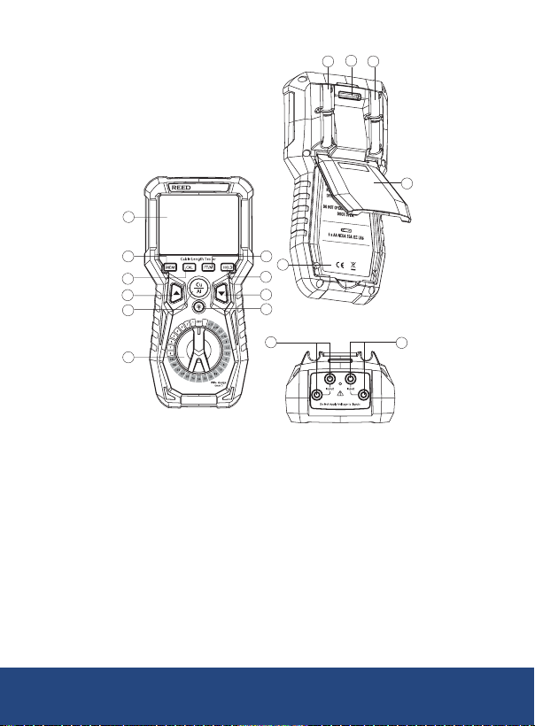
Instrument Description
13
12
12
14
16
1
2
3
4
5
6
1. LCD Display
2. MEM Button
3. CAL Button
4. UP Button
5. Cu/Al Button
6. Function Dial
7. Backlight Button
8. DOWN Button
R5340
10
t
Ω
11
9
8
7
15
11. Battery cover
12. Test Lead Holders
13. Hanging strap bracket
14. Kickstand
15. Black Test Leads
Input Terminal
16. Red Test Leads
Input Terminal
9. HOLD Button
10. FT/M Button
1-877-849-2127 | [email protected] | www.reedinstruments.com
REED Instruments
7
Page 8
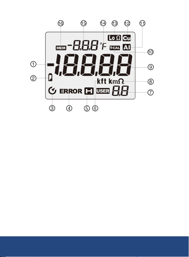
Display Description
1. Negative Value Indicator
2. Low battery Indicator
3. Auto Power Off Indicator
4. ERROR Status Indicator
5. Data Hold Indicator
6. Unit of length measurement
7. User-selected
programming mode
8. Resistance unit of measure
9. Measurement Value
10. Calibration Status Indicator
11. Aluminum Indicator
12. Copper Indicator
13. Low Resistance Indicator
14. Temperature Unit of measure
15. Temperature Measurement
Value
16. Memory location
1-877-849-2127 | [email protected] | www.reedinstruments.com
REED Instruments
8
Page 9
Operating Instructions
Warning: Electric shock hazard: Do not connect the unit to live
voltage. Contact with live circuits could result in severe injury
or death.
Power ON/OFF
Rotate the function dial to any position to power on the meter. If the meter
does not turn on, check the batteries. For details on battery replacement,
refer to section ''Battery replacement'' for details.
Calibration Procedure
Every time the meter is turned ON, it must be calibrated before use.
1. Turn the function dial from the OFF position to the Ω position.
2. Connect the red Kelvin clip to the meter's red terminals.
3. Connect the black Kelvin clip to the meter’s black terminals.
Important: Ensure that both the calibration bar and the jaws of the
Kelvin clips are clean before proceeding.
I
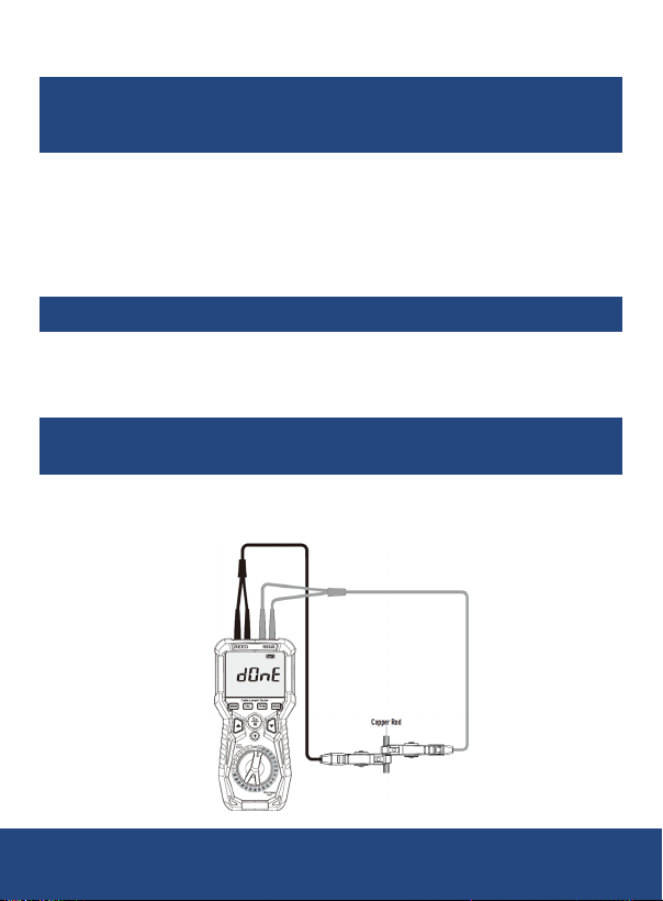
4. Connect the two alligator clips to the supplied copper rod.
5. Adjust the clips so they are as close together as possible along
the rod.
continued...
1-877-849-2127 | [email protected] | www.reedinstruments.com
REED Instruments
9
Page 10
6. Press the CAL button when ready.
MEM
T-CAL
MEM
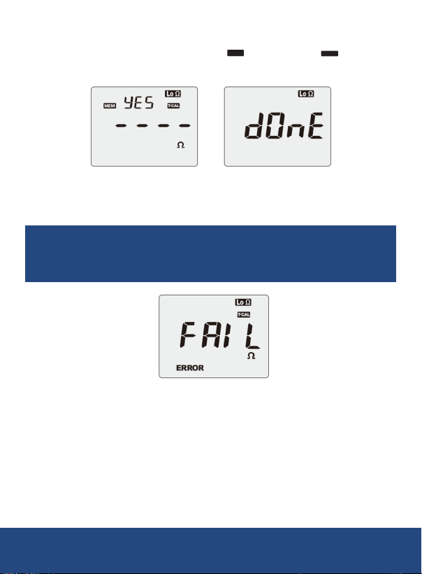
7. The display will alternate between “ YES” and “no
”, ashing
twice each time as shown below.
8. Press the MEM button. If the display briey indicates “dOnE” and
then returns to resistance measurement mode, the calibration
has succeeded.
Note: If the display indicates "FAIL" after pressing the MEM Button,
the calibration has failed. Check whether the connections and contacts
are correct and secure.
9. If you press the CAL button again, the meter will exit calibration
mode and return to resistance measurement mode.
continued...
1-877-849-2127 | [email protected] | www.reedinstruments.com
REED Instruments
10
Page 11

Measuring the Length of a Cable
Warning: Electric shock hazard: Do not connect the unit to live
voltage. Contact with live circuits could result in severe injury
or death.
1. Turn the function dial from the OFF position to the Ω position.
2. Follow the steps outlined in the "Calibration Procedure" to ensure
accurate measurements.
Note: Temperature affects the accuracy of the readings. For best
results, allow the meter and the cable to reach the same ambient
temperature. Typically, this takes about 30 minutes.
3. Strip the insulation from both ends of the cable. Ensure the exposed
conductor is clean and fully visible. If necessary, use abrasive paper
to remove any oxide layer from the exposed ends.
Note: Both ends must be clean for accurate measurement.
4. Adjust the function dial to the appropriate cable gauge position
based on the cable being measured.
Example: For a cable gauge of 1 mm², set the rotary switch to
the “1” position.
5. If the cable is copper, press the Cu/AI button until "Cu" appears on
the display. If the cable is aluminum, press the Cu/AI button until "AI"
appears on the display.
6. Press the FT/M button to choose the unit of measurement (feet
or meters).
7. Attach one alligator clip to one end of the cable and the other
alligator clip to the opposite end of the cable.
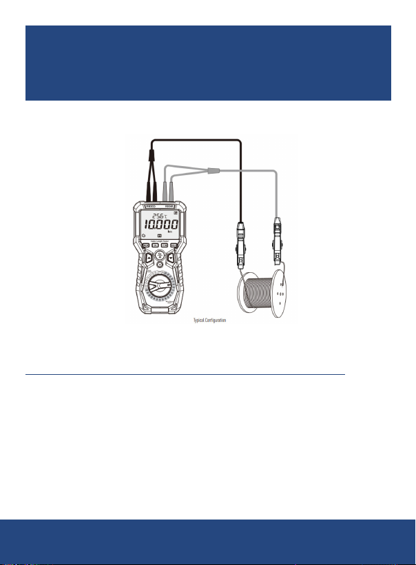
8. The display will indicate the measured length of the cable in the
selected unit (feet or meters) and the ambient temperature.
continued...
1-877-849-2127 | [email protected] | www.reedinstruments.com
REED Instruments
11
Page 12
Note: If the temperature falls below 23°F (-5°C), the display will
show "-OL" to indicate it is out of range. If the temperature exceeds
122°F (50°C), the display will show “OL” to indicate it is out of range.
Press and hold the Cu/AI button to toggle between Celsius (°C) and
Fahrenheit (°F) display modes.
9. Once the measurement is complete, disconnect the alligator clips
from the cable.
User-selected Programming Mode:
The User Selected Mode offers the following functionalities:
Resistance Parameter Storage: Users can save the resistance
parameters of a specic cable for length measurements of cables with the
same characteristics (i.e., same gauge and conductor material).
Accurate Length Measurement: It allows precise measurement of
standard gauge cables.
Versatility: In this mode, users can measure the length of various metal
cables, including copper and aluminum cables.
continued...
1-877-849-2127 | [email protected] | www.reedinstruments.com
REED Instruments
12
Page 13
Note: The sample length of test cables must be:
• Between 4 m and 100 m in METER mode
• Between 13.1 ft and 320 ft in FEET mode
• How to Save the Resistance of a Test Cable
How to Save the Resistance of a Test Cable
Note: Before starting, prepare a sample cable with a length between
4 m and 100 m (or 13.1 ft to 320 ft in FEET mode). This sample will
be programmed into the meter so that it can correctly measure and
store the resistance of this specic cable type. Ensure the cable being
measured is not energized or live.
1. Turn the function dial from the OFF position to the Ω position.
2. Follow the steps outlined in the “Calibration Procedure” to calibrate
the meter.
Note: Temperature affects the accuracy of the readings. For best
results, allow the meter and the cable to reach the same ambient
temperature. Typically, this takes about 30 minutes.
3. Remove the insulation from both ends of the sample cable.
Note: Ensure the two conductors are clean and fully exposed. Use
a grinding pad if needed to clean the exposed cable ends for better
conductivity and easier clamping with the test rods.
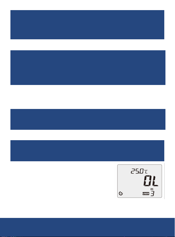
4. Use the function dial to select a
User-Dened Mode from 1 to 8.
5. The selected User-Dened mode will be
displayed in the bottom right corner of the
screen. If the selected User-Dened mode
already contains a stored cable parameter,
the screen will display "OL" as shown below.
continued...
1-877-849-2127 | [email protected] | www.reedinstruments.com
REED Instruments
13
Page 14

6. Press the FT/M button to toggle between feet (FT) and meters (M) as
MEM
T-CAL
MEM
the unit of measurement.
7. Press the CAL button. to enter the sample cable length setting
mode. In this mode, the display alternates between " YES" and
"no
" with “MEM” and “TCAL” ashing twice each cycle.
8. Use the Up/Down buttons to adjust the displayed value.
9. Adjust the display until it matches the actual length of the sample
cable to be measured.
10. Attach one alligator clip to each end of the sample cable, ensuring
secure connections at both ends.
11. Press the MEM button. If the display briey indicates “dOnE” and
then returns to measurement mode, the setting has succeeded.
Note: If the display indicates "FAIL" and "ERROR", the setting has
failed. In this case, verify that all connections and contacts are secure
and correct.
12. Press the CAL button to resume normal operation.
13. Remove the two alligator clips from the sample cable.
Measuring Cable Length in User-Defined Mode
1. Turn the function dial from the OFF position to the Ω position.
2. Follow the steps outlined in the “Calibration Procedure” to calibrate
the meter.
Note: Temperature affects the accuracy of the readings. For best
results, allow the meter and the cable to reach the same ambient
temperature. Typically, this takes about 30 minutes.
3. Remove the insulation from both ends of the sample cable.
continued...
1-877-849-2127 | [email protected] | www.reedinstruments.com
REED Instruments
14
Page 15
Note: Ensure the two conductors are clean and fully exposed. Use
a grinding pad if needed to clean the exposed cable ends for better
conductivity and easier clamping with the test rods.
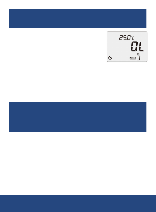
4. Use the function dial to select a
User-Dened Mode from 1 to 8.
5. The selected User-Dened mode will be
displayed in the bottom right corner of the
screen. If the selected User-Dened mode
already contains a stored cable parameter,
the screen will display "OL" as shown below.
6. Press the FT/M button to toggle between feet (FT) and meters (M) as
the unit of measurement.
7. Attach one alligator clip to each end of the cable under test, ensuring
secure connections at both ends.
8. The display will indicate the measured length of the cable in the
selected unit (feet or meters) and ambient temperature.
Note: If the temperature falls below 23°F (-5°C), the display will
show "-OL" to indicate it is out of range. If the temperature exceeds
122°F (50°C), the display will show “OL” to indicate it is out of range.
Press and hold the Cu/AI button to toggle between Celsius (°C) and
Fahrenheit (°F) display modes.
9. Once the measurement is complete, disconnect the alligator clips
from the cable.
1-877-849-2127 | [email protected] | www.reedinstruments.com
REED Instruments
15
Page 16
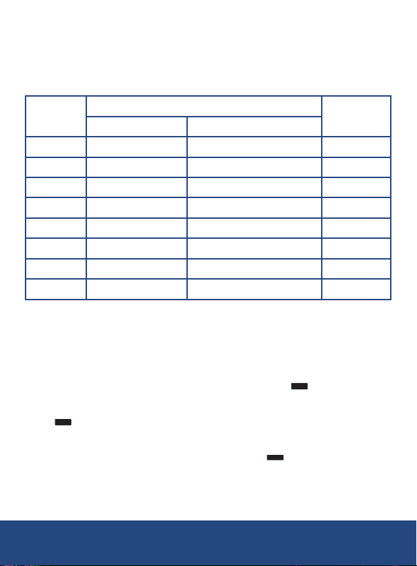
Programmable Switch Positions User’s Table
MEM
T-CAL
MEM
MEM
Use this table to log the cable sizes assigned to each programmable
switch position. For exibility, make entries using an erasable
medium (e.g., pencil or erasable marker), as switch positions may be
reprogrammed in the future.
Switch
Position
Size Type
Gauge
Material
Type
1 mm² AWG kcmil aught Cu or AI
2 mm² AWG kcmil aught Cu or AI
3 mm² AWG kcmil aught Cu or AI
4 mm² AWG kcmil aught Cu or AI
5 mm² AWG kcmil aught Cu or AI
6 mm² AWG kcmil aught Cu or AI
7 mm² AWG kcmil aught Cu or AI
8 mm² AWG kcmil aught Cu or AI
Clearing Memory Locations in User-Selected Mode
1.
Ensure the test rod is disconnected from the meter before proceeding.
2. Turn the function dial to select the user-dened mode whose
memory you want to clear.
3. Press the CAL button. The display will indicate " YES".
4. To clear the memory, press the MEM button. The display will indicate
" CLr" conrming that the stored data in the selected memory
location will be erased.
5. After clearing, the display will indicate "out
resume normal operation.
" will automatically
1-877-849-2127 | [email protected] | www.reedinstruments.com
REED Instruments
16
Page 17

Measuring Resistance
1. Turn the function dial from the OFF position to the “Ω‘’ position.
2. Follow the steps outlined in the “Calibration Procedure” to calibrate
the meter.
Note: Temperature affects the accuracy of the readings. For best
results, allow the meter and the cable to reach the same ambient
temperature. Typically, this takes about 30 minutes.
3. Remove the insulation from both ends of the cable.
Note: Ensure the two conductors are clean and fully exposed. Use
a grinding pad if needed to clean the exposed cable ends for better
conductivity and easier clamping with the test rods.
4. Attach one alligator clip to each end of the cable under test, ensuring
secure connections at both ends.
5.
The display will indicate the impedance value and ambient temperature.
Note: If the temperature falls below 23°F (-5°C), the display will
show “-OL” to indicate it is out of range. If the temperature exceeds
122°F (50°C), the display will show “OL” to indicate it is out of range.
Press and hold the Cu/AI button to toggle between Celsius (°C) and
Fahrenheit (°F) display modes.
6. Once the measurement is complete, disconnect the alligator clips
from the cable.
Data Hold
1. While taking a measurement, press the HOLD button to freeze the
current reading on the LCD display.
2. While in this mode an "H" symbol will appear.
3. Press the HOLD button again to resume normal operation.
1-877-849-2127 | [email protected] | www.reedinstruments.com
REED Instruments
17
Page 18

Backlight
Press the Backlight button to manually turn on the backlight. To turn off
the backlight, press the backlight button again.
Battery Replacement
1. When the low battery icon appears on the display, the batteries must
be replaced.
2. Use a Phillips head screwdriver to remove the battery cover located
on the back of the meter.
3. Replace the 6 x "AA" batteries.
4. Secure the battery cover back and tighten the screw
Applications
• Cable length verication during installation and maintenance projects.
• Resistance testing to ensure cable integrity and reliability.
• Troubleshooting and diagnosing electrical faults in cables.
• Industrial and commercial wiring assessments.
• Quality control checks in manufacturing and production environments.
• Use in telecommunications and data cabling installations
REED Instruments
1-877-849-2127 | [email protected] | www.reedinstruments.com
Page 19
Product Warranty
REED Instruments guarantees this instrument to be free of defects in
material or workmanship for a period of one (1) year from date of shipment.
During the warranty period, REED Instruments will repair or replace, at no
charge, products or parts of a product that proves to be defective because
of improper material or workmanship, under normal use and maintenance.
REED Instruments total liability is limited to repair or replacement of the
product. REED Instruments shall not be liable for damages to goods,
property, or persons due to improper use or through attempts to utilize the
instrument under conditions which exceed the designed capabilities. In
order to begin the warranty service process, please contact us by phone
at 1-877-849-2127 or by email at [email protected] to discuss
the claim and determine the appropriate steps to process the warranty.
Product Disposal and Recycling
Please follow local laws and regulations when disposing or recycling your
instrument. Your product contains electronic components and must be
disposed of separately from standard waste products.
Product Support
If you have any questions on your product, please contact your authorized
REED distributor or REED Instruments Customer Service by phone at
1-877-849-2127 or by email at [email protected].
Please visit www.REEDInstruments.com for the most
up-to-date manuals, datasheets, product guides and software.
Product specifications subject to change without notice.
All rights reserved. Any unauthorized copying or reproduction of
this manual is strictly prohibited without prior written permission
from REED Instruments.
REED Instruments
1-877-849-2127 | [email protected] | www.reedinstruments.com
 Loading...