

Page 1
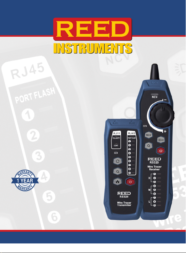
Wire Tracer
and Circuit
Testing Kit
R5320
Instruction
Manual
www.GlobalTestSupply.com
Page 2

Table of Contents
Introduction ................................................................................................... 2
Product Quality .............................................................................................. 3
Safety ............................................................................................................ 3
Features ......................................................................................................... 3
Included ......................................................................................................... 4
Specications ............................................................................................. 4-5
Instrument Description .................................................................................. 6
Operating Instructions .............................................................................. 7-10
Network Line Tracking .............................................................................. 7
Telephone Line Tracking ........................................................................... 7
Power Cable Tracking ............................................................................ 7-8
Demonstration of Tracking Operation ....................................................... 8
RJ45 Cable Validating ...........................................................................8-9
RJ11 Cable Validating .............................................................................. 9
Non-Contact Voltage Detector ............................................................... 10
Turning Flashlight On/Off ........................................................................ 10
Applications ................................................................................................... 9
Product Care ................................................................................................. 9
Product Warranty ........................................................................................ 10
Product Disposal and Recycling ................................................................. 10
Product Support .......................................................................................... 10
Introduction
Thank you for purchasing your REED R5320 Wire Tracer and Circuit
Testing Kit. Please read the following instructions carefully before using
your instrument. By following the steps outlined in this manual your meter
will provide years of reliable service.
www.GlobalTestSupply.com
2
Page 3

Product Quality
This product has been manufactured in an ISO9001 facility and has been
calibrated during the manufacturing process to meet the stated product
specications. If a certicate of calibration is required please contact the
nearest authorized REED distributor or authorized Service Center. Please
note an additional fee for this service will apply.
Safety
• Never attempt to repair or modify your instrument.
• Servicing should only be provided by an authorized service center.
• Do not use or store this device in dusty, hot or wet environments.
• Do not use this device on live circuits exceeding 60VAC or 70VDC.
• Do not use this device during thunderstorms.
Features
• Test modes include: identifying and locating wires, validating cable/line
connections and verifying telephone line continuity/line polarity
• Modular adapters provide direct connection to RJ45 and RJ11 wiring
• Alligator clip adapter allows for easy connection to non-terminated cables
• Adjustable sensitivity wheel improves wire identication and eliminates
false detection
• Visual (ashing LEDs) and audible (pulsating beeper) indicators
• Integrated ashlight supports applications in low lit environments
• Built-in non-contact voltage detector
• Earphone jack for loud environments (earphones sold separately)
• Rechargeable batteries
• Low battery indicator and auto shut-off
www.GlobalTestSupply.com
3
Page 4

Included
• Transmitter
• Receiver
• Micro-USB Charging Cable
• RJ11 Adapter Cable
• RJ45 Adapter Cable
• RJ11 Alligator Clip Adapter Cable
• Carrying Case
Specifications
Testing Modes
• RJ45 (Ethernet) Network cable tracing
• RJ11 (Telephone) Line tracing
• Miscellaneous line/Wire tracing (using RJ11/Alligator clip adapter)
• RJ45 (Ethernet) Network cable validation
• RJ11 (Telephone) Line validation
• Non-contact voltage detector
Transmitter
• Port ashing: Port ashing and wire tracking can be turned on at same time
• Wire tracking signal frequency: 125kHz
• Test Speed: Fast (2Hz) Slow (1Hz)
• Network Wire: Shielded/Unshielded
• Open-short circuit Test: Load <9kΩ: Short; Load >17kΩ: Open
• Open polarity test: Test range: DC: +5V~+70V or -70V~-5V
• Input protection: 60VDC
Receiver
• Wire tracking sensitivity: RJ11 ≤9842' (3000m)/RJ45 ≤328' (100m)
• Input Impedance: >100MΩ
www.GlobalTestSupply.com
continued...
4
Page 5

General Specifications
Signal Mode: Modulation signal (125kHz)
Visual Indicator: Yes (LEDs)
Audible Indicator: Yes (Pulsating beeper)
Sensitivity Settings: Yes (Adjustable wheel)
Compatible Wire Type: RJ-11, RJ-45, Alligator clips for connection
to non-terminated wire
Non-Contact
Voltage Detector: Yes (40 to 1000VAC)
Earphone Jack: Yes (3.5mm)
Built-in Flashlight: Yes
Auto Shut-off: Transmitter: Yes (after 60 mins)
Receiver: Yes (after 10 mins)
Power Supply: 1050mAh rechargeable Li-ion battery
Charging Time: Approx. 2 hours (Micro-USB)
Low Battery Indicator: Yes
Battery Life: Transmitter: >8 hours
Receiver: >5 hours
Operating Temperature: 14 to 122°F (-10 to 50°C)
Operating Humidity Range: 20 to 75%
Operating Altitude: ≤6561' (2000m)
Product Certications: CE, RoHS
Dimensions:
Transmitter: 5.1 x 2 x 1.1" (130 x 51 x 28mm)
Receiver: 7.8 x 1.9 x 1.3" (197 x 48 x 34mm)
Weight: Transmitter: 3.4oz (95g)
Receiver: 4.5oz (127g)
www.GlobalTestSupply.com
5
Page 6
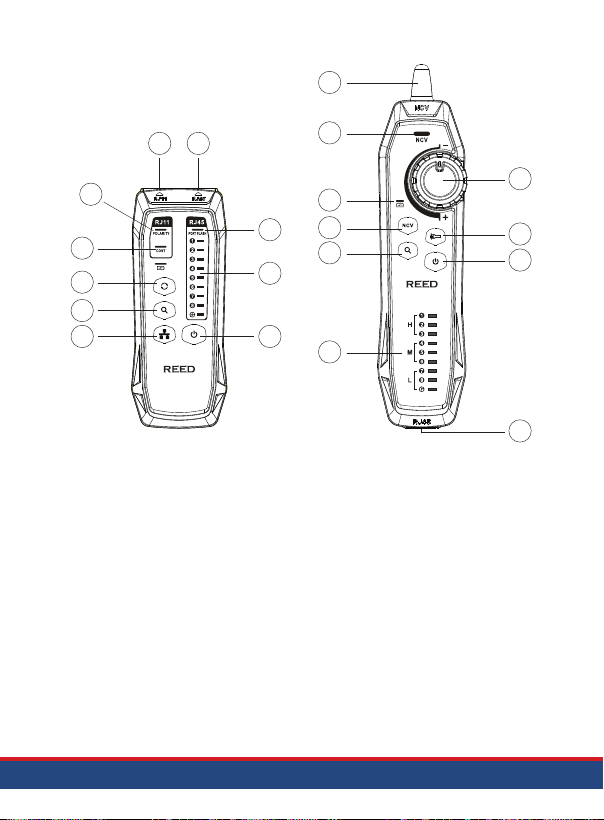
Instrument Description
11
1
10
2
3
4
5
6
R5320
Wire Tracer
Transmitter
1. RJ11 Jack
2. POLARITY Indicator
3. CONT Indicator
4. Switch Button
5. Tracking Button
6. Validating Indicator
7. Power Button
8. Line Sequence Indicators
9. PORT FLASH Light
10. RJ45 Jack
12
13
14
9
15
8
7
16
11. Antenna
12. NCV Indicator
13. Charging State Indicator
14. NCV Button
15. Tracking Button
16. Line Sequence Indicators
17. RJ45 Jack
18. Power Button
19. Flashlight Button
20. Sensitivity Knob
R5320
Wire Tracer
Receiver
20
19
18
17
www.GlobalTestSupply.com
6
Page 7

Operating Instructions
Network Line Tracking
1. Insert the RJ45 plug of the network line into the RJ45 jack of
the transmitter.
2. Plug the other end of the RJ45 plug into the port.
3. Turn on the transmitter by pressing the Power button.
4. Press the button on the transmitter to enable the tracking
function. In tracking mode, press the button to enable the ashing
function simultaneously. If the target network line is connected to an
active switch, router or network card, the "PORT FLASH" light of the
transmitter will ash synchronously with the network port indicator.
5. Turn on the receiver by pressing the Power button.
6. Press the button on the receiver to start tracking. When beeps
are heard, the target network line has been located. If the application
involves multiple cables, it is recommended to use the sensitivity
wheel. Louder sound signies the target cable is in close proximity.
Telephone Line Tracking
1. Insert the RJ11 plug of the telephone line into the RJ11 jack of
the transmitter.
2. Plug the other end of the RJ11 cable into the telephone jack.
3. Turn on the transmitter by pressing the Power button.
4. Press the button on the transmitter to enable the tracking function.
5. Turn on the receiver by pressing the Power button.
6. Press the button on the receiver to start tracking. When beeps are
heard, the target telephone line has been located. If the application
involves multiple cables, it is recommended to use the sensitivity
wheel. Louder sound signies the target cable is in close proximity.
Power Cable Tracking
1. Use the RJ11 alligator clip adapter cable to connect the transmitter
and metal cable being tracked.
2. Turn on the transmitter by pressing the Power button.
continued...
www.GlobalTestSupply.com
7
Page 8
3. Press the button on the transmitter to enable the tracking function.
4. Turn on the receiver by pressing the Power button.
5. Press the
button
on the receiver to start tracking. When beeps are
heard, the target cable has been located. If the application involves
multiple cables, it is recommended to use the sensitivity wheel.
Louder sound signies the target cable is in close proximity.
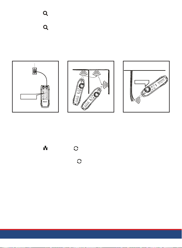
Demonstration of Tracking Operation
Wall socket
(RJ11/RJ45 socket)
Test indicators
Locating cables
R5320
Wire Tracer
Receiver
R5320
Wire Tracer
R5320
Wire Tracer
Transmitter
Receiver
Isolating cables
Volume control
Receiver
Wire Tracer
R5320
RJ45 Cable Validating
1. Insert both ends of the RJ45 cable under test into the RJ45 jacks of
the transmitter and receiver.
2. Power ON the transmitter and receiver.
3. Press the button, the button ashes ashes, and the validating
function is enabled.
4. During the test, press
slow mode.
the button
to switch between fast and
www.GlobalTestSupply.com
continued...
8
Page 9
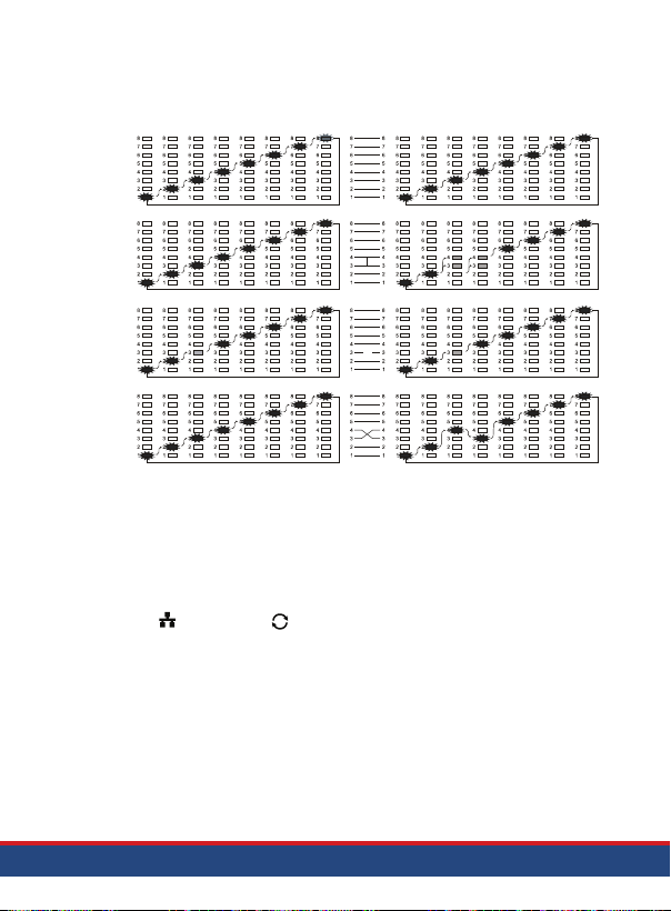
5. Verify the state of the cable (good wiring, short circuit, open circuit,
Good wiring
Short circuit
Open circuit
miswire) according to the line sequence indicators on the transmitter and
receiver. See image below for additional information on the indicators.
R5320 Transmitter Lamp Signal R5320 Receiver Lamp Signal
1 to 8
3, 4
3
3, 4
Misfire
RJ11 Cable Validating
1. Insert the RJ11 plug of the cable under test into the RJ11 jack of
the transmitter.
2. Plug the other end of the RJ11 cable into the telephone jack.
3. Turn on the transmitter by pressing the Power button.
4. Press the
5.
is enabled.
The "CONT" indicator lights up green to indicate open circuit of the
cable, and red to indicate short circuit of the cable. The
"POLARITY" indicator lights up green to indicate that the cable has a
positive polarity voltage, red to indicate that the cable has a reverse
polarity voltage, and green and red ash alternately to indicate a
ringing signal or AC power on the cable.
button, the button ashes, and the validating function
www.GlobalTestSupply.com
continued...
9
Page 10

Non-Contact Voltage Detector
Press the NCV button on the receiver to enable the NCV function. When
the target cable or socket has an AC voltage over 40V, the receiver will
beep and the "NCV" indicator will ash simultaneously.
Turning Flashlight On/Off
Press the button to turn the ashlight of the receiver ON/OFF.
Applications
• IT professionals cable installation/labelling and troubleshooting
• Telecom and Datacom technicians
• Identify and locate non-energized wires in walls, ceilings, and oors
Product Care
To keep your instrument in good working order we recommend the following:
• Store your product in a clean, dry place.
• If your instrument isn't being used for a period of one month or longer
please remove the battery.
• Clean your product and accessories with biodegradable cleaner. Do not
spray the cleaner directly on the instrument. Use on external parts only.
Product Warranty
REED Instruments guarantees this instrument to be free of defects in
material or workmanship for a period of one (1) year from date of shipment.
During the warranty period, REED Instruments will repair or replace, at no
charge, products or parts of a product that proves to be defective because
of improper material or workmanship, under normal use and maintenance.
REED Instruments total liability is limited to repair or replacement of the
product. REED Instruments shall not be liable for damages to goods,
property, or persons due to improper use or through attempts to utilize the
instrument under conditions which exceed the designed capabilities. In
order to begin the warranty service process, please contact us by phone at
1-877-849-2127 or by email at [email protected] to discuss the
claim and determine the appropriate steps to process the warranty.
www.GlobalTestSupply.com
10
Page 11

Product Disposal and Recycling
Please follow local laws and regulations when disposing or recycling your
instrument. Your product contains electronic components and must be
disposed of separately from standard waste products.
Product Support
If you have any questions on your product, please contact your authorized
REED distributor or REED Instruments Customer Service by phone at
1-877-849-2127 or by email at [email protected].
Please visit www.REEDINSTRUMENTS.com for the most
up-to-date manuals, datasheets, product guides and software.
Product specifications subject to change without notice.
All rights reserved. Any unauthorized copying or reproduction of
this manual is strictly prohibited without prior written permission
from REED Instruments.
www.GlobalTestSupply.com
11
Page 12

TEST & MEASURE
WITH CONFIDENCE
CHECK OUT OUR LATEST PRODUCTS!
www.GlobalTestSupply.com
 Loading...