


1000A AC/DC
True RMS
Clamp Meter
R5040
Instruction
Manual
www.GlobalTestSupply.com

Table of Contents
Introduction ................................................................................................... 3
Product Quality .............................................................................................. 3
Safety .........................................................................................................3-4
Features ......................................................................................................... 4
Included ......................................................................................................... 4
Specications ............................................................................................. 5-6
Instrument Description .................................................................................. 7
Display Description ....................................................................................... 7
Operating Instructions .............................................................................. 8-11
AC/DC Current Measurements ................................................................ 8
AC/DC Voltage Measurements ................................................................. 8
Resistance Measurements ....................................................................... 8
Diode and Continuity Measurements ....................................................... 9
Capacitance Measurements ..................................................................... 9
Frequency or % Duty Cycle Measurements ............................................. 9
Temperature Measurements ................................................................... 10
Non-Contact AC Voltage Measurements ............................................... 10
Min/Max Recording ................................................................................ 10
Relative Mode ......................................................................................... 10
Data Hold ............................................................................................... 11
Auto and Manual Range ......................................................................... 11
Battery Replacement ................................................................................... 11
Applications ................................................................................................. 11
Accessories and Replacement Parts .......................................................... 12
Product Care ............................................................................................... 12
Product Warranty ........................................................................................ 13
Product Disposal and Recycling ................................................................. 13
Product Support .......................................................................................... 13
www.GlobalTestSupply.com
2

Introduction
Thank you for purchasing your REED R5040 1000A AC/DC True RMS
Clamp Meter. Please read the following instructions carefully before using
your instrument. By following the steps outlined in this manual your meter
will provide years of reliable service.
Product Quality
This product has been manufactured in an ISO 9001 facility and has
been calibrated during the manufacturing process to meet stated product
specications. If a certicate of calibration is required please contact the
nearest authorized REED distributor or authorized Service Center. Please
note an additional fee for this service will apply.
Safety
• Never attempt to repair or modify your instrument. Dismantling your
product, other than for the purpose of replacing batteries, may cause
damage that will not be covered under the manufacturer's warranty.
Servicing should only be provided by an authorized service center.
• Do not exceed the maximum allowable input range of any function.
• Do not apply voltage to the meter when resistance function is selected.
• Set the function switch OFF when the meter is not in use.
• Set the function switch to the appropriate position before measuring.
• When measuring volts do not switch to current/resistance modes.
• When changing ranges using the selector switch always disconnect the
test leads from the circuit under test.
• Do not exceed the maximum rated input limits.
• Improper use of this meter can cause damage, shock, injury or death.
• Read and understand this user manual before operating the meter.
• Always remove the test leads before replacing the battery.
• Inspect the condition of the test leads and the meter itself for any
damage before operating.
www.GlobalTestSupply.com
continued...
3

• Repair or replace any damage before use.
• Use great care when taking measurements if the voltages are greater
than 25VAC RMS or 35VDC as they are considered a shock hazard.
• Remove the battery if the meter is to be stored for long periods.
• Always discharge capacitors and remove power from the device under
test before performing diode, resistance, or continuity tests.
• Voltage checks on electrical outlets can be difcult and misleading
because of the uncertainty of connection to the recessed
electrical contacts.
• If the equipment is used in a manner not specied by the manufacturer,
the protection provided by the equipment may be impaired.
Features
• Measures AC/DC current/voltage, resistance, capacitance, frequency,
duty cycle, and temperature
• 50,000-count backlit LCD display and analog bargraph
• Low battery and overrange indicators
• Built-in non-contact voltage detector with LED indicator
• True RMS AC measurements
• Min/Max, display hold and relative mode
• Diode test and continuity check functions
• Durable double molded plastic housing
• Cat. III 600V safety rating
Included
• Test Leads
• Thermocouple Wire Probe
• Thermocouple Adapter
• Soft Carrying Case
• Battery
www.GlobalTestSupply.com
4

Specifications
AC/DC Current
Range: 500, 1000A
Accuracy: AC: ±(2.8% rdg. +30 dgt.)
DC: ±(2.5% rdg. +30 dgt.)
Resolution: 0.01, 0.1, 1A
AC/DC Voltage
Range: AC: 500mV, 5, 50, 500, 750V
DC: 500mV, 5, 50, 500, 1000V
Accuracy: AC: ±(1.0% rdg. +30 dgt.)
DC: ±(0.1% rdg. +4 dgt.)
Resolution: AC/DC: 0.1mV, 0.001, 0.01, 0.1, 1V
Resistance
Range: 500Ω, 5, 50, 500kΩ, 5, 50MΩ
Accuracy: ±(1.0% rdg. +4 dgt.)
0.1Ω, 0.001, 0.01, 0.1kΩ, 0.001, 0.01MΩ
Capacitance
Range: 500, 5000nF, 50, 500µF, 5mF
Accuracy: ±(3.5% rdg. +10 dgt.)
Resolution: 0.01, 0.1nF, 0.01, 0.1μF, 0.1mF
Frequency
Range: 10kHz
Accuracy: ±(0.3% rdg. +2 dgt.)
Resolution: 0.001Hz
Temperature
Range: -148 to 1832°F (-100 to 1000°C)
Accuracy: ±(1.0% rdg. + 4.5°F)
±(1.0% rdg. + 2.5°C)
Resolution: 1°F, 1°C
www.GlobalTestSupply.com
continued...
5

General Specifications
Range Selection: Autoranging/Manual
True RMS: Yes
Display: 50,000 count LCD display
Display Hold: Yes
Max/Min: Yes
Relative Mode: Yes
Diode Test: Yes
Backlit Display: Yes
Analog Bargraph: Yes (61-segment)
Continuity Check: Audible signal if resistance <35Ω
Duty Cycle: Yes
Non-Contact Voltage Detector: Yes
Autoshut Off: Yes (after 15 minutes)
Power Supply: 9V Battery
Low Battery Indicator: Yes
Jaw Opening: 1.5" (40mm), up to 500 MCM
Overvoltage Category: CAT. III 600V
Product Certications: CE
Operating Temperature: 32 to 122°F (0 to 50°C)
Storage Temperature: -4 to 140°F (-20 to 60°C)
Dimensions: 9.1 x 3.0 x 1.5" (232 x 77 x 39mm)
Weight: 9.6oz (271g)
www.GlobalTestSupply.com
6
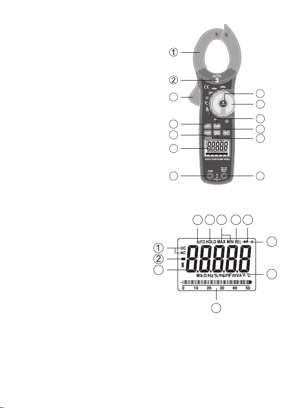
Instrument Description
1. Current Clamp
2. Non-Contact AC Voltage
Indicator Light
3. Clamp Trigger
4. Data Hold and Backlight Button
5. Rotary Function Switch
6. Hz% Hold Button
7. RANGE Select Button
8. MODE Select Button
9. Relative Button
10. MIN/MAX Hold Button
11. LCD Display
12. COM Input Jack
13. Positive Input Jack
Display Description
1. AC/DC Indicator
2. Negative Reading Indicator
3. 50,000 Count Main Display
4. Analog Bargraph
5. Units of Measurement
6. Audible Continuity Indicator
7. Diode Test Mode Indicator
8. Relative Mode Indicator
9. Max/Min Mode Indicator
10. Data Hold Indicator
11. Auto Range Mode Indicator
3
6
8
11
12
11
R5040
10
4
5
7
9
10
13
89
7
6
3
5
4
www.GlobalTestSupply.com
7
Operating Instructions
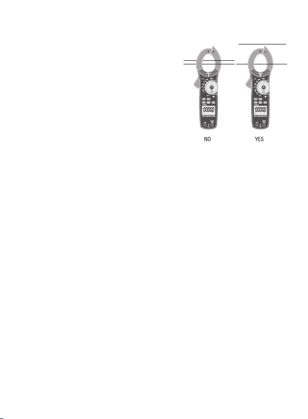
AC/DC Current Measurements
1. Set the rotary function switch to the
1000ADC, 600ADC, 1000AAC, or
600AAC range. If the range needed
is not known, select the higher range
rst then move to the lower range if
necessary.
2. Press the trigger to the open jaw and
fully enclose one conductor.
3. The LCD will display the reading.
AC/DC Voltage Measurements
1. Insert the black test lead into the negative COM terminal and the red
test lead into the positive V terminal.
2. Set the rotary function switch to the V position, and select either AC
or DC with the MODE button.
3. Select Hz% or ACV with the Hz% button.
4. Connect the test leads in parallel to the circuit under test.
5. The LCD will display the reading.
Resistance Measurements
1. Insert the black test lead into the negative COM terminal and the red
test lead into the positive V terminal.
2. Set the rotary function switch to the Ω position.
3. Touch the test probe tips across the circuit or component under test.
It is best to disconnect one side of the device under test so the rest
of the circuit will not interfere with the reading.
4. The LCD will display the reading.
R5040
R5040
www.GlobalTestSupply.com
continued...
8

Diode and Continuity Measurements
1. Insert the black test lead into the negative COM terminal and the red
test lead into the positive V diode terminal.
2. Turn the rotary function switch to the Ω position. Press the MODE
button until the Diode Test indicator appears on the display.
3. Touch the test probes to the diode under test. Forward voltage will
indicate 0.4V to 0.7V. Reverse voltage will be indicated by "OL".
Shorted devices will indicate near 0mV and an open device will be
indicated by "OL" in both polarities. For continuity tests, if the
resistance is <40Ω, a tone will sound.
Capacitance Measurements
1. To avoid electric shock, disconnect power to the unit under test and
discharge all capacitors before taking any capacitance measurements.
Remove the batteries and unplug the line cords.
2. Set the rotary function switch to the CAP position.
3. Insert the black test lead into the negative COM terminal and the red
test lead into the positive V terminal.
4. Touch the test leads to the capacitor under test.
5. The LCD will display the reading.
Frequency or % Duty Cycle Measurements
1. Set the rotary function switch to the V position.
2. Select ACV with the MODE button and press the Hz/% button to
indicate "Hz" in the display.
3. Insert the black test lead into the negative COM terminal and the red
test lead into the positive V terminal.
4. Touch the test probe tips to the circuit under test.
5. The LCD will display the reading.
continued...
www.GlobalTestSupply.com
9

Temperature Measurements
1. To avoid electric shock, disconnect both test probes from any source
of voltage before making a temperature measurement.
2. Set the function switch to TEMP. Press the MODE button to change
between °C and °F.
3. Insert the Temperature Probe into the negative COM and the
positive V terminals, making sure to observe the correct polarity.
4. Touch the Temperature Probe head to the area to be measured. Keep
the probe touching the part under test until the reading stabilizes
(about 30 seconds).
5. The LCD will display the reading.
Note: To avoid electric shock, be sure the thermocouple has been removed
before changing to another function.
Non-Contact AC Voltage Measurements
1. Set the rotary function switch to the V position.
2. Touch the probe tip to the hot conductor or insert into the hot side of
the electrical outlet. If AC voltage is present, the detector will light up.
3. The conductors in electrical cord sets are often twisted. For best
results, rub the probe tip along a length of the cord to assure placing
the tip in close proximity to the live conductor.
4. The detector is designed with high sensitivity. Static electricity or
other sources of energy may randomly trip the sensor.
Min/Max Recording
While in Manual Range, select the proper range before selecting MIN/MAX
to ensure that the MIN/MAX reading will not exceed the testing range.
Press the MIN/MAX button to select the minimum reading. Press the
MIN/MAX button again to select the maximum reading. Press the MIN/
MAX button again to exit and resume normal measuring.
Relative Mode
Press the REL button for Capacitance Zero & Offset Adjustment.
www.GlobalTestSupply.com
continued...
10

Data Hold
1. While taking a measurement, press the HOLD button to freeze the
current reading on the display.
2. While in this mode, a HOLD symbol will appear.
3. Press the HOLD button again to exit and resume normal operation.
Auto and Manual Range
When the meter is rst turned on, it automatically goes into AutoRanging.
This automatically selects the best range for the measurements being
made and is generally the best mode for most measurements. For
measurement situations requiring that a range be manually selected,
perform the following:
1. Press the RANGE button. The "Auto Range" display indicator will
turn off and "Manual Range" display indicator will turn on.
2. Press the RANGE button to step through the available ranges until
you select the range you want.
3. Press and hold the RANGE button for 2 seconds to exit "Manual
Ranging" mode and return to "AutoRanging".
Battery Replacement
1. Remove the Phillips screw on the back of the meter.
2. Open the battery compartment.
3. Replace the 1 x 9V battery and secure the battery compartment.
Applications
• Industrial maintenance teams performing scheduled and preventative
maintenance on electro-mechanical equipment and systems.
• Facilities, building maintenance and electricians looking to troubleshoot
electrical equipment installation problems.
www.GlobalTestSupply.com
11

Accessories and Replacement Parts
• R2990 Thermocouple Adapter
• R5400 Line Splitter
• R1000 Safety Test Lead Set, Double Insulated
• R1020 Fused Test Lead Set
• TP-01 Type K Thermocouple Wire Probe
• R2920 Surface Thermocouple Probe
• R2930 Right Angle Thermocouple Surface Probe
• R2940 Air/Gas Thermocouple Probe
• R2950 Immersion Thermocouple Probe
• R2960 Needle Tip Thermocouple Probe
• CA-05A Soft Carrying Case
• R9940 Hard Shell Carrying Case
Don't see your part listed here? For a complete list of all accessories and
replacement parts visit your product page on www.reedinstruments.com.
Product Care
To keep your instrument in good working order we recommend the following:
• Store your product in a clean, dry place.
• Change the battery as needed.
• If your instrument isn't being used for a period of one month or longer
please remove the battery.
• Clean your product and accessories with biodegradable cleaner. Do not
spray the cleaner directly on the instrument. Use on external parts only.
www.GlobalTestSupply.com
12

Product Warranty
REED Instruments guarantees this instrument to be free of defects in
material or workmanship for a period of one (1) year from date of shipment.
During the warranty period, REED Instruments will repair or replace, at no
charge, products or parts of a product that proves to be defective because
of improper material or workmanship, under normal use and maintenance.
REED Instruments total liability is limited to repair or replacement of the
product. REED Instruments shall not be liable for damages to goods,
property, or persons due to improper use or through attempts to utilize the
instrument under conditions which exceed the designed capabilities. In
order to begin the warranty service process, please contact us by phone at
1-877-849-2127 or by email at info@reedinstruments.com to discuss the
claim and determine the appropriate steps to process the warranty.
Product Disposal and Recycling
Please follow local laws and regulations when disposing or recycling your
instrument. Your product contains electronic components and must be
disposed of separately from standard waste products.
Product Support
If you have any questions on your product, please contact your authorized
REED distributor or REED Instruments Customer Service by phone at
1-877-849-2127 or by email at info@reedinstruments.com.
Please visit www.REEDInstruments.com for the most
up-to-date manuals, datasheets, product guides and software.
Product specifications subject to change without notice.
All rights reserved. Any unauthorized copying or reproduction of
this manual is strictly prohibited without prior written permission
from REED Instruments.
www.GlobalTestSupply.com
13

TEST & MEASURE
WITH CONFIDENCE
CHECK OUT OUR LATEST PRODUCTS!
www.GlobalTestSupply.com
 Loading...