


Model
Instruction
Manual
Compact Digital
Multimeter with
Temperature
R5008
www.GlobalTestSupply.com

Table of Contents
Safety ...................................................................................................... 2-3
Features .......................................................................................................4
Instrument Decription ..................................................................................4
Specications .......................................................................................... 5-9
Operating Instructions ........................................................................... 9-11
Safety
The following safety information must be observed to insure maximum
personal safety during the operation of this meter:
• Do not use the meter if the meter or test leads look damaged, or if you
suspect that the meter is not operating properly
• Never ground yourself when taking electrical measurements. Do not
touch exposed metal pipes, outlets, xtures, or anything which might be
a grounding potential
• Keep your body from grounding by wearing dry clothing, using rubber
shoes, rubber mats, or any other approved insulating material
• Ensure that you isolate the circuit and that there is no electrical current
running through it before you cut, unsolder, or break it. Small amounts
of current can be dangerous
• Use caution when working above 60V DC or 30V AC RMS. Such
voltages are a shock hazard
• When using the probes, keep your ngers behind the nger guards
• Measuring voltage which exceeds the limits of the Multimeter may
damage the meter and expose the operator dangerous currents of
electricity. Always recognize the meter’s voltage limits as stated on the
front of the meter.
www.GlobalTestSupply.com
2

Never apply voltage or current to the meter that exceeds the specied maximum:
M AX
Input Limits
Function Maximum Input
V DC or V AC 600V DC, 600V AC
mA DC/AC 400mA DC/AC
A DC/AC
Frequency, Resistance, Capacitance,
Duty Cycle, Diode Test, Continuity
10A DC/AC (30 second max
every 15 minutes)
250V DC/AC
Temperature 250V DC/AC
Safety Symbols
This symbol adjacent to another symbol, terminal, or operating
device, indicates that the operator must refer to an explanation
in the Instruction Manual to avoid personal injury or damage to
the meter.
WARNING
This WARNING symbol indicates a potentially hazardous situation,
which if not avoided, could result in serious injury or death.
CAUTION
This CAUTION symbol indicates a potentially hazardous situation,
which if not avoided, may result damage to the product.
This symbol advises the user that the terminal(s), marked as so,
500V
must not be connected to a circuit point at which the voltage, with
respect to grounding, exceeds the stated amount of Volts (in this
case 500 VAC or VDC).
This symbol, adjacent to one or more terminals, identies them
as being associated with ranges that may, in normal use, be
subjected to particularly hazardous voltages. For maximum safety,
the meter and its test leads should not be handled when these
terminals are energized.
3
www.GlobalTestSupply.com
Features
• Measures AC/DC voltage and current, frequency, resistance,
capacitance and temperature
• Diode check and continuity functions
• Relative and data hold functions
• Double molded plastic housing
• Cat. III 600V safety rating
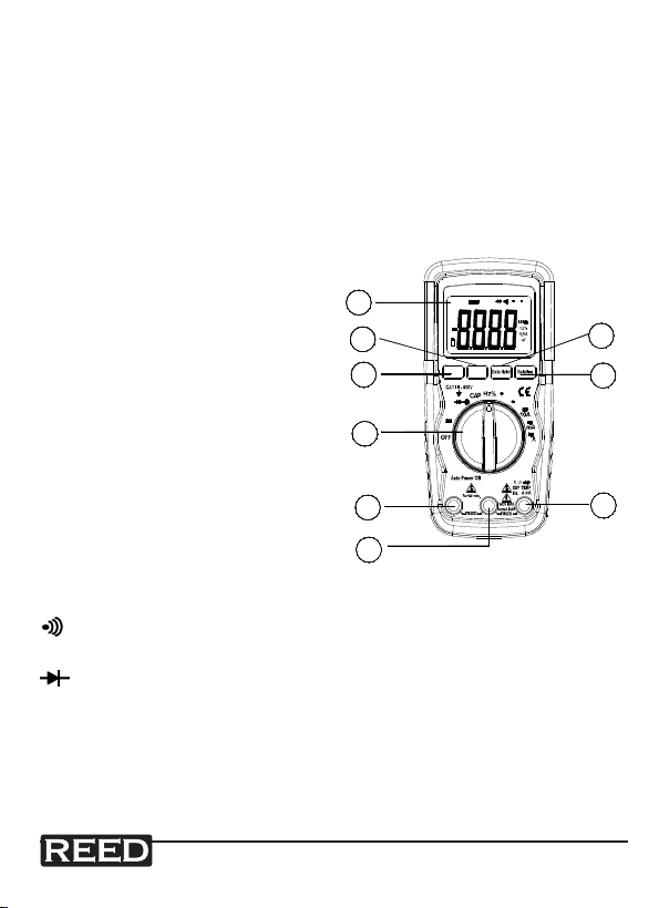
Instrument Description
AUTO
REL
1. 4000 count LCD
2. Function switch
3. 10A (Positive) input jack for
10A DC or AC measurements
1
DC
AC
7
6
4. COM (Negative) input jack
5. Positive input jack
6. MODE button
7. RANGE button
8. DATA HOLD button
9. RELATIVE button
2
3
V
10A COM
4
Display Symbol Descriptions
Continuity
BAT Low Battery
Diode
DATA HOLD Data Hold
AUTO Auto Ranging
AC Alternating Current or Voltage
DC Direct Current or Voltage
C
F
RangeMode
C
F
Ω㦣
μ�
MAX
every
15 min.
8
9
μ�
5
www.GlobalTestSupply.com
4

Specifications
Range Selection Autoranging/Manual
Display 4,000 count LCD display
Display Hold Yes
Peak Hold Yes
Relative Mode Yes
Diode Test Yes
Continuity Check Audible signal if resistance ≤150Ω
Duty Cycle Yes (0.1 to 99.9%)
Kick Stand Yes
Auto Power Off Yes (after 15 minutes)
Power Supply 9V Battery
Low Battery Indicator Yes
Fuse Protection Yes
Replaceable Test Leads Yes
Overvoltage Category CAT. III 600V
Product Certications CE
Operating Temperature 32 to 122°F (0 to 50°C)
Storage Temperature -4 to 140°F (-20 to 60°C)
Dimensions 5.9 x 2.8 x 1.9in (150 x 70 x 48mm)
Weight 9oz (255g)
Accuracy
Accuracy is given at 18 to 28°C (65 to 83°F), less than 70% RH
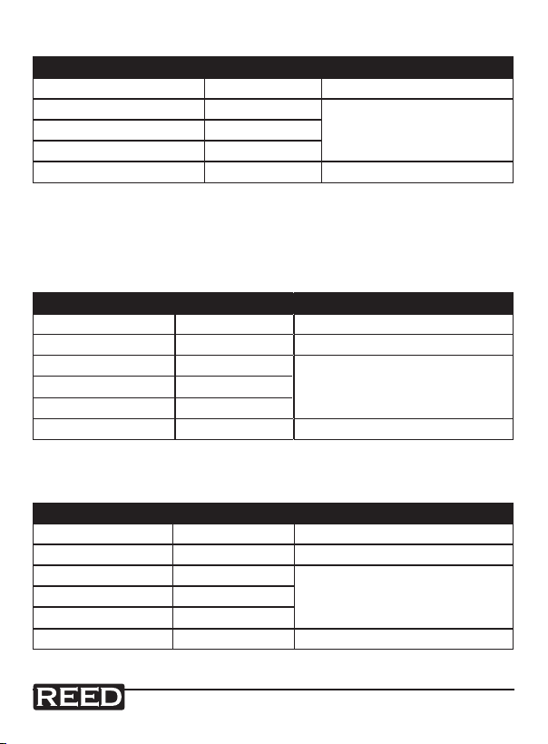
DC Voltage (Auto-ranging)
Range Resolution Accuracy
400.0mV 0.1mV ±0.5% of rdg ±2 dgts
4.000V 1mV
40.00V 10mV
400.0V 100mV
600V 1V ±1.5% of rdg ±2 dgts
±1.2% of rdg ±2 dgts
www.GlobalTestSupply.com
5

Input Impedance: 7.8MΩ
Maximum Input: 600V DC or 600V AC RMS
AC Voltage (Auto-ranging except 400mV)
Range Resolution Accuracy
400.0mV 0.1mV ±1.5%of rdg ±15 dgts
4.000V 1mV ±1.2% of rdg ±3 dgts
40.00V 10mV
400.0V 100mV
600V 1V ±2.0% of rdg ±4 dgts
Input Impedance: 7.8MΩ
Frequency Range: 50 to 400Hz
Maximum Input: 600V DC or 600V AC RMS
±1.5% of rdg ±3 dgts
DC Current (Auto-ranging for uA and mA)
Range Resolution Accuracy
400.0uA 0.1uA ±1.0% of rdg ±3 dgts
4000uA 1uA
40.00mA 10uA
400.0mA 100uA
10A 10mA ±2.5% of rdg ±5 dgts
Overload Protection: 0.5A / 250V and 10A / 250V Fuse
Maximum Input: 400mA DC or 400mA AC RMS on uA / mA ranges,
10A DC or AC RMS on 10A range
±1.5% of rdg ±3 dgts
www.GlobalTestSupply.com
6
AC Current (Auto-ranging for uA and mA)
Range Resolution Accuracy
400.0uA 0.1uA V1.5% of rdg ±5 dgts
4000uA 1uA
40.00mA 10uA
400.0mA 100uA
10A 10mA ±3.0% of rdg ±7 dgts
Overload Protection: 0.5A / 250V and 10A / 250V Fuse
Frequency Range: 50 to 400 Hz
Maximum Input: 400mA DC or 400mA AC RMS on uA / mA ranges,
10A DC or AC RMS on 10A range
±1.8% of rdg ±5 dgts
Resistance (Auto-ranging)
Range Resolution Accuracy
400.0Ω 0.1Ω ±1.2% of rdg ±4 dgts
4.000kΩ 1Ω ±1.0% of rdg ±2 dgts
40.00kΩ 10Ω
400.0kΩ 100Ω
4.000MΩ 1kΩ
40.00MΩ 10kΩ ±2.0% of rdg ±3 dgts
Input Protection: 250V DC or 250V AC RMS
±1.2% of rdg ±2 dgts
Capacitance (Auto-ranging)
Range Resolution Accuracy
4.000nF 1pF ±5.0% of rdg ±50 dgts
40.00nF 10pF ±5.0% of rdg ±7 dgts
400.0nF 0.1nF
4.000uF 1nF
40.00uF 10nF
200.0uF 0.1uF ±5.0% of rdg ±5 dgts
Input Protection: 250V DC or 250V AC RMS
±3.0% of rdg ±5 dgts
www.GlobalTestSupply.com
7
Frequency (Auto-ranging)
Range Resolution Accuracy
9.999Hz 0.001Hz
99.99Hz 0.01Hz
999.9Hz 0.1Hz
9.999kHz 1Hz
99.99kHz 10Hz
999.9kHz 100Hz
9.999MHz 1kHz ±1.5% of rdg ±4 dgts
Sensitivity: >0.5V RMS while ≤1MHz; >3V RMS while >1MHz
Overload Protection: 250V DC or AC RMS
±1.5% of rdg ±5 dgts
±1.2% of rdg ±3 dgts
Duty Cycle
Range Resolution Accuracy
0.1%~99.9% 0.1% ±1.2% of rdg ±2 dgts
Pulse Width: >100us, <100ms;
Frequency Width: 5Hz – 150kHz
Sensitivity: >0.5V RMS
Overload Protection: 250V DC or AC RMS
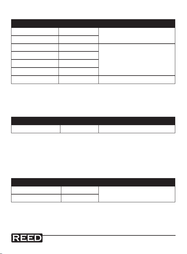
Temperature
Range Resolution Accuracy
-20 ~+760°C 1°C
-4 ~+1400°F 1°F
Sensor: Type K Thermocouple
Overload Protection: 250V DC or AC RMS
±3% of rdg ±5°C/9°F
www.GlobalTestSupply.com
8

Diode Test
Test current Resolution Accuracy
0.3mA typical 1 mV ±10% of rdg ±5 dgts
Open Circuit Voltage: 1.5V DC typical
Overload Protection: 250V DC or AC RMS
Audible Continuity
Audible Threshold: Less than 150Ω; Test current: <0.3mA
Overload Protection: 250V DC or AC RMS
Operating Instructions
WARNING: Risk Of Electrocution!
High-voltage circuits, both AC and DC, are very dangerous and should
be measured with great care.
1. Always turn the function switch to the OFF position when the meter is
not in use. This meter has Auto OFF that automatically shuts the meter
OFF if 15 minutes has elapsed between uses.
2. If "OL" appears in the display during a measurement, the measured
value exceeds the range you have selected. Change to a higher range.
NOTE: On some low AC and DC voltage ranges, with the test leads not
connected, the display may show a random, changing reading. This is
normal and is caused by the high-input sensitivity. The reading will
stabilize and give a proper measurement when connected to a circuit.
www.GlobalTestSupply.com
9

MODE Button
Press the MODE button to switch between Diode/Continuity, DC/AC and
Hz/%Duty for the respected function
RANGE Button
When the meter is rst turned on, it automatically goes into AutoRanging.
This automatically selects the best range for the measurements being
made, and is generally the best mode for most measurements. For
measurement situations requiring that a range be manually selected,
perform the following:
1. Press the RANGE button. The "AUTO" display indicator will turn off.
2. Press the RANGE button to step through the available ranges until
you select the range you want.
Press and hold the RANGE button for 2 seconds to exit the
ManualRanging mode and return to AutoRanging
DATA HOLD Button
Press the DATA HOLD button to pause the reading on the indicator. HOLD
will appear on the display to indicate the function. Press the DATA HOLD
button to return to normal operation.
RELATIVE Button
The relative measurement feature allows you to make measurements
relative to a stored reference value. A reference value (Voltage, Current,
etc.) can be stored and measurements can be made in comparison to that
value. The displayed value is the difference between the reference value
and the measured value.
1. Perform any measurement as described in the operating instructions.
2. Press the RELATIVE button to store the reading that is on the screen.
The "REL" indicator will appear on the display.
3. The display will now indicate the difference between the stored value
and the measured value.
4. Press the RELATIVE button to return to normal operation.
www.GlobalTestSupply.com
10

DC Voltage Measurement
CAUTION: Do not measure DC voltages if a motor on the circuit is
being switched ON or OFF. Large voltage surges may occur that can
damage the meter.
1. Set the function switch to the V DC position ("mV" will appear in the
display).
2. Insert the black test lead banana plug into the negative (COM) jack and
the red test lead banana plug into the positive (V) jack.
3. Touch the test probe tips to the circuit under test. Be sure to observe
the correct polarity (red lead to positive, black lead to negative).
4. Read the voltage in the display. The display will indicate the proper
decimal point and value. If the polarity is reversed, the display will show
(-) minus before the value.
AC Voltage Measurement
WARNING: Risk of Electrocution. The probe tips may not be long
enough to contact the live parts inside some 240V outlets for
appliances because the contacts are recessed deep in the outlets.
As a result, the reading may show 0 volts when the outlet actually
has voltage on it. Make sure the probe tips are touching the metal
contacts inside the outlet before assuming that no voltage is present.
CAUTION: Do not measure AC voltages if a motor on the circuit is
being switched ON or OFF. Large voltage surges may occur that can
damage the meter.
1. Set the function switch to the V AC position.
2. Insert the black test lead banana plug into the negative (COM) jack and
the red test lead banana plug into the positive (V) jack.
3. Touch the test probe tips to the circuit under test.
4. Read the voltage in the display. The display will indicate the proper
decimal point, value and symbol (AC, V, etc.).
www.GlobalTestSupply.com
11

Notes _________________________________________
________________________________________________
________________________________________________
________________________________________________
________________________________________________
________________________________________________
________________________________________________
________________________________________________
________________________________________________
________________________________________________
________________________________________________
________________________________________________
________________________________________________
________________________________________________
________________________________________________
________________________________________________
________________________________________________
________________________________________________
www.GlobalTestSupply.com
12
 Loading...