

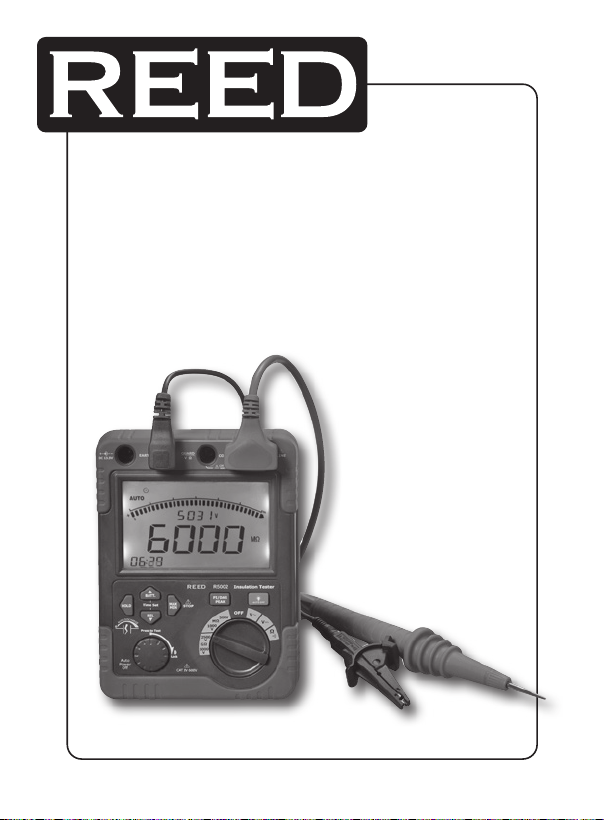
Model
High Voltage Insulation
Resistance Tester
R5002
www.GlobalTestSupply.com

Table of Contents
Safety ............................................................................................ 3
Features .........................................................................................4
Specications .............................................................................4-6
Instrument Description .............................................................7-10
Operating Instructions ............................................................11-18
AC/DC Voltage Measurement ................................................... 11
Internal Power Source Measurement ........................................ 12
Low Resistance Measurement & Continuity Check .................... 12
Measuring Insulation Resistance ............................................... 13
Auto-discharge ......................................................................... 14
Insulation Resistance Measurement Principle ............................ 14
Polarization Index and Dielectric Absorption Ratios ..............14-15
Use of Guard terminal ..........................................................15-16
Data Hold ................................................................................. 16
Peak Hold ............................................................................16-17
MAX/MIN Value ......................................................................... 17
Relative Value ............................................................................ 17
Emergency Stop ....................................................................... 18
Backlight ................................................................................... 18
Auto power off .......................................................................... 18
Battery Replacement ................................................................... 18
www.GlobalTestSupply.com
2

Safety
• Complies with IEC61010 safety measurement requirement in
pollution degree 2, overvoltage category (CAT. IV 600V) and
double insulation
• Do not apply more than 600V to this meter
• Do not use this meter around explosive gas, vapor, or dust
• Do not use this meter in a wet environment
• When using the test leads, keep your ngers away from the lead
contacts, behind the nger guards
• Do not use this meter with any parts or cover removed
• Do not come in contact the circuit under test while taking
measurements
• Do not use this meter if it is damaged or parts are exposed; look
for cracks or missing plastic
• Be careful when working above 30V rms
• Discharge all circuits after measuring high voltage
• Place test leads in their proper input terminals
• Make sure all the test leads are rmly connected to the input
terminals
• Make sure the insulation resistance tester is turned off when
opening the battery compartment
• Do not change the battery when in a wet environment
• Do not use or store this meter in high temperatures, humidity,
explosive environments, and near strong magnetic elds
• Dry this meter before storing if wet
• When not in use, set the range selector switch to the “OFF”
position and remove the test leads
• Remove the batteries if the instrument is not used for a long
period of time
www.GlobalTestSupply.com
3

Features
• Insulation test range: 0.1MΩ to 60GΩ
• Insulation test voltages: 500V, 1000V, 2500V, 5000V
• AC/DC voltage: 0.5V to 600V
• 200mA Continuity
• Resistance: 0.1Ω to 6kΩ
• Auto-discharge function & voltage output warning function
• Backlight level selector
• Live circuit warning symbols plus audible warning
• Live circuit detection prevents insulation test if >30V is detected
• Auto-power off function & battery check
• Time set measurement function
• Polarization index measurement (PI)
• Dielectric absorption ratio measurement (DAR)
• Auto ranging with 6000 counts LCD display and bar-graph
• MAX/MIN, PEAK, Relative Value, & Data Hold functions for AC/DC
voltage measurements
• 6000 count LCD display with bar-graph
Specifications
Operating conditions: 32 to 104°F (0 to 40°C); 80% RH
Storage conditions: 14 to 140°F (-10 to 460°C); <80% RH
Sampling rate: 2.5 readings per second
Fuse: 500mA/600V (6 x 32mm) ceramic 3AG fast blow
Zero adjust: Automatic
Auto power off: 20 min
Power supply: 8 C Batteries or AC Adapter (included)
Dimensions: 7.8 x 5.8 x 3.4" (198 x 148 x 86mm)
Weight: 3lbs (1.5kg)
continued ...
www.GlobalTestSupply.com
4

Includes: One black alligator test lead, one green alligator
test lead, one red alligator test lead, one red
2-prong alligator test lead, batteries,
and a tool box
DC/AC Voltage Measurement
Range: 0.5-600.0V
Resolution: 0.1V
Accuracy: AC: +1.0% reading + 5 digits (40 to 60Hz)
+2.5% reading + 10 digits (61 to 400Hz)
DC: +1.0% reading + 5 digits
Insulation Resistance Measurement
Rated voltage 500V 1000V 2500V 5000V
0.005-6MΩ 0.005-6MΩ 0.05-60MΩ 0.05-60MΩ
Measuring range
(Auto-ranging)
Open circuit
voltage
Rated current
Short-circuit current: Approx 1mA
Accuracy: +2.5% reading + 15 digits (at 0.005 to 600.0MΩ);
+3% reading + 15 digits (at 0.61 to 6.00GΩ);
+4% reading + 15 digits (at 6.1 to 60.0GΩ)
Voltage monitor range: 5 to 6000VDC (resolution 1V)
Accuracy: +1.5% reading + 5 digits
6.01-60MΩ 6.01-60MΩ 60.1-600MΩ 60.1-600MΩ
60.1-600MΩ 60.1-600MΩ 0.61-6GΩ 0.61-6GΩ
0.61-6GΩ 0.61-6GΩ 6.1-60GΩ 6.1-60GΩ
DC 500V
+20%, -0%
1-1.2mA (at
0.5MΩ load)
DC 1000V
+20%, -0%
1-1.2mA (at
1MΩ load)
DC 2500V
+20%,-0%
1-1.2mA (at
2.5MΩ load)
DC 5000V
+20%,-0%
1-1.2mA (at
5MΩ load)
www.GlobalTestSupply.com
continued ...
5

Low Resistance Measurement & Continuity Check
Range Resolution Accuracy
Resistance (Auto-ranging)
Continuity Buzzer: ≤35Ω
Short circuit Current: ≥200mA
Open Circuit Test Voltage: ≥4.5V
0.1 to 600Ω 0.1Ω
6.01 to 6kΩ 0.001kΩ
+1.5% reading
+ 10 digits
+1.5% reading
+ 15 digits
For service on this or any other REED product or information on other
REED products, contact REED Instruments at info@reedinstruments.com
www.GlobalTestSupply.com
6

Instrument Description
1. Insulation resistance test/lock button
2. Relative/Time-down button
3. Data hold button
4. Internal battery check/time-up button
5. MAX/MIN & Test button
6. LCD display
7. Power adaptor input terminal
8. EARTH: high resistance measurement input
9. V/Ω input terminal & GUARD: grounding protection input terminal
10. COM & high voltage line shielding input terminal
11. LINE: 500 to 5000V high voltage output terminal
12. PI/DAR, peak voltages measurement & time clear button
13. Backlight levels button
14. Function switch
15. Test leads
www.GlobalTestSupply.com
7
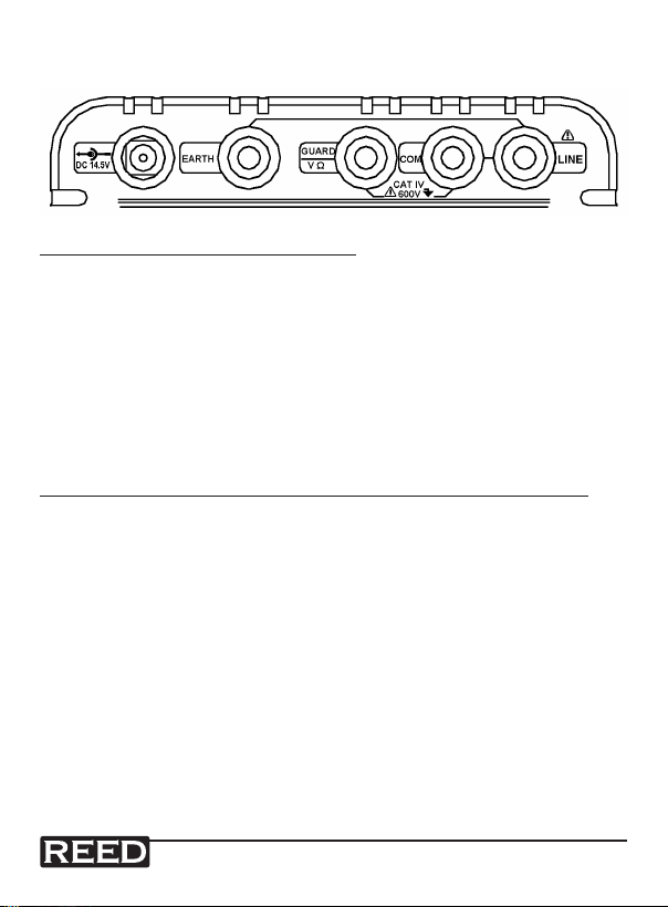
Input Terminals
Insulation Resistance Measurement
LINE: 500V to 5000V range insulation resistance measurement/high
voltage line output terminal (LINE + COM: two plugs red test lead
to one alligator clip)
COM: Return terminal for all measurements
(LINE + COM: two prong red test lead)
GUARD: Grounding protection input terminal (black test led)
EARTH: Insulation resistance measurement input terminal
(green test lead)
ACV/DCV/Low Resistance Measurements & Continuity Check
V/Ω: Input for voltage, low resistance measurements & continuity
check (red test lead)
COM: Return terminal for all measurements (black test lead)
www.GlobalTestSupply.com
8

Front Panel
HOLD: Freezes current reading
Backlight: Turns the backlight on, makes it brighter, and turns it off
Insulation Resistance Measurement
TEST/LOCK: Press and hold to test or lock on insulation resistance
measurement
Time-up: Adjust timer up
Time-down: Adjust timer down
PI: Polarization index measurement
DAR: Dielectric absorption ratio measurement
STOP: Stop insulation resistance measurements
and high voltage output
AC/DC Measurements
MAX/MIN: MAX/MIN record
PEAK: PEAK-MAX/PEAK-MIN capture
REL: Relative measurement
BATT: Check battery power
www.GlobalTestSupply.com
9
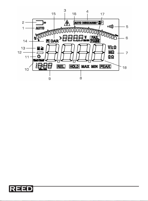
LCD Display
1. Auto-ranging indicator
2. Battery life indicator
3. High voltage output or >30V AC/DC voltage indicator
4. Indicator for automatically discharged
5. Continuity buzzer indicator
6. Analogue bar graph
7. Unit symbols
8. Function indicators
9. Clock
10. Timer 1 & Timer 2 indicators
11. Active timer symbol
12. Indicates for negative reading
13. AC/DC indicators
14. Polarization index
15. Dielectric absorption ratio
16. Secondary reading display
17. Check feature pass or fail
18. Primary reading display
www.GlobalTestSupply.com
10
Operating Instructions
After pressing the TEST button under insulation measurement, the wire
will generate high voltage. Do not touch it to avoid electric shock.
AC/DC Voltage Measurement
To avoid electric shock, do not test if voltage to ground AC/DC is more
than 600V, even if the line voltage is below 600V.
1. Set the rotary switch to the AC or DC position.
2. Connect the red test lead to the VΩ terminal and the black test lead
to the COM terminal.
3. Connect the test leads to the circuit under test.
4. Read the voltage value on the LCD.
5. When measuring DC voltage, if the red test lead is negative
voltage, “-” will appear on the display.
www.GlobalTestSupply.com
11

Internal Power Source Measurement
1. Disconnect the test leads.
2. Set the switch to DC.
3. Press the BATT button.
4. Read the voltage value
on the LCD.
5. After 5 seconds the meter
will auto-off or press the
BATT button to turn off the
battery voltage function.
Low Resistance Measurement & Continuity Check
Do not run this test unless AC/DC = 0V. Do not use this mode to
check diodes.
1. Set the rotary switch to the Ω position.
2. Connect the red test lead
to the VΩ terminal and
the black lead to the
COM terminal.
3. Connect the tips of
the test leads to the
circuit under test.
4. Read the resistance
value on the display.
5. When the resistance
of a circuit is less
than 50Ω, the audible
tone will sound.
www.GlobalTestSupply.com
12

Measuring Insulation Resistance
• Prior to testing check the circuit with a high voltage detector to be
sure that there is no electrical charge
• It is highly recommended to wear insulated gloves while taking
high voltage measurements
• Do not make measurements with the battery compartment open
• Do not take measurements during thunderstorms
• Be sure to connect the black Earth Cord to the Earth terminal of
the circuit under test
• Measurements cannot be made if the “>30V” live circuit warning
appears or if “AUTO DISCHARGE” appears on the LCD screen
along with a warning buzzer
1. Check the amount of voltage that can be applied to the circuit
under test, and set the range switch to the desired insulation
resistance range.
2. Connect the black Earth cord to the Earth terminal on the circuit
under test.
3. Touch circuit with the tip of the red line probe and press the
“PRESS TO TEST” button. The buzzer will sound intermittently
during measurement.
4. The measured value will display on the LCD, and it is automatically
held after measurement.
5. At any output voltage, when the tested resistance is less than
10MΩ, the testing time cannot exceed 10 seconds continuously.
Note: Do not touch the circuit under test immediately after testing.
Capacitance stored in the circuit may cause electric shock. Leave
test leads connected to the circuit and never touch the circuit until the
discharge is complete.
www.GlobalTestSupply.com
13

Auto-discharge
This function releases the capacitance stored in a circuit after testing.
The LCD will ash “AUTO DISCHARGE” when the meter is in discharge
condition and the live voltage monitor will display “O V”. This function
will be released by removing test leads 2 sec or more before discharge is
complete. Set the range switch to “OFF” position, and remove test leads
from the instrument.
Insulation Resistance Measurement Principle
Insulation tests should only be performed on de-energized circuits.
Continuous Insulation Resistance Measurement
Press and turn the “PRESS TO TEST” button clockwise to perform a
continuous insulation resistance measurement. After testing, turn the
button counterclockwise to the initial position. A beep will sound and the
reading will hold on the LCD for 10 seconds.
Timer Insulation Resistance Measurement
This is a function to automatically conduct a test at a set time (from 1 min
to 15 min).
1. Press the Time-up and Time-down buttons to set the time from 1
min to 15 min.
2. To activate the timed insulation resistance measurement, press and
turn the “PRESS TO TEST” button clockwise till it locks.
3. After testing, turn the button counterclockwise to the initial
position. A beep will sound and the reading will hold in the LCD for
10 seconds.
Polarization Index and Dielectric Absorption Ratios
Polarization Index (PI) is the ratio of a 10-minute to 1-minute insulation
resistance. Polarization index = resistance value measured after 10
min (Time2)/resistance value measured after 1 min (Time1). Dielectric
Absorption Ratio (DAR) is the ratio of a 1-minute to 30-second insulation
resistance. Dielectric Absorption Ratio = resistance value measured after
1 min (Time2)/resistance value measured after 30 sec (Time1).
continued ...
www.GlobalTestSupply.com
14

1. Press the PI/DAR button to select PI or DAR Measurement.
2. The LCD will display PI & Time1/Time2 or DAR & Time1/Time2.
3. To begin measuring, press and turn the “PRESS TO TEST” button
clockwise till it locks.
4. After testing, turn the button to counterclockwise to the initial
position. A beep will sound and will display “PASS if the reading
is PI/DAR>4, or “FAIL” if the reading is PI/DAR<1. The reading will
hold for 10 seconds.
PI standard
PI value 2 to 4 (typically3): Considered as good insulation (older types)
PI value 1 to 1.5: Not acceptable (older types)
PI value 1: (Very high insulation resistance)
Modern type of (good) insulation systems
PI value 1.0 or less: Fail
Example: If measuring a B-class insulation material and the polarization
index is 1.1, the insulating material contains too much water or is seriously
polluted. The polarization index is below the minimum acceptable value
and you need to repair or replace parts.
DAR standard
DAR value 1.6 or more: Excellent
DAR value 1.25 to 1.6: PASS
DAR value <1.25 or less: Fail
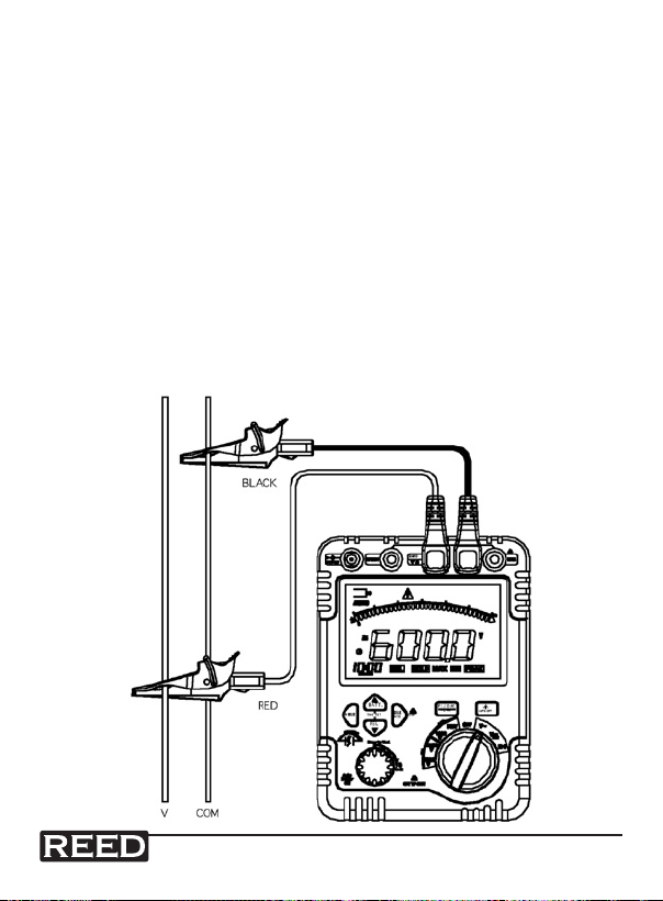
Use of Guard terminal
When measuring a cable, the leakage current owing on the surface of
cable jacket and the current owing inside the insulator combine and may
cause error in value. To prevent this error, wind a conductive wire around
the point where leakage current ows, then connect it to the Guard
terminal as shown in the gure below.
www.GlobalTestSupply.com
continued ...
15

This removes the surface leakage resistance of the cable insulation so you
only measure the volume resistance of the insulator. Make sure to use the
Guard cord supplied with this instrument to connect the instrument to the
Guard terminal.
Data Hold
This function freezes the reading on the display. Press the HOLD key
momentarily to activate or to exit the hold function.
Peak Hold
The Peak Hold function captures the peak AC/DC Voltage from 0.5V to
600V, and can capture peaks from 10 to 100 milliseconds in duration.
1. Press the PEAK button. The symbol “PEAK” will appear on the
LCD.
2. Press the MAX/MIN button to activate the MAX/MIN recording
mode. The symbol “MAX & PEAK” will appear on the LCD. The
screen will display and hold the maximum reading and will update
only when a new “MAX” reading occurs.
3. Press the MAX/MIN button again and “MIN &PEAK” will appear on
the screen. The LCD will display and hold the minimum reading and
update only when a new “MIN” reading occurs.
www.GlobalTestSupply.com
continued ...
16

4. Press the MAX/MIN button again, and a “MAX MIN PEAK” symbol
will appear on the LCD. The meter will display the present reading,
but will continue to update and store the max and min readings.
5. To exit MAX/MIN-PEAK mode press the PEAK button or hold the
MAX/MIN button for 2 seconds.
MAX/MIN Value
Only for AC/DC voltage measurement
1. Press the MAX/MIN button to activate the MAX/MIN recording
mode. The symbol “MAX” will appear on the screen. The LCD will
display and hold the maximum reading and will update only when a
new “MAX” reading occurs.
2. Press the MAX/MIN button again and “MIN” will appear on the
screen. The meter will display and hold the minimum reading and
will update only when a new “MIN” reading occurs .
3. Press the MAX/MIN button and “MAX MIN” will appear on the
screen. The meter will display the present reading, but will continue
to update and store the max and min readings.
4. To exit MAX/MIN mode press and hold the MAX/MIN buttons for 2
seconds.
Relative Value
(Only for AC/DC voltage measurement)
The relative measurement feature allows you to take AC/DC voltage
measurements relative to a stored reference value. The displayed value is
the difference between the reference value and the measured value.
1. Press the REL button to store the reading currently on display. The
“REL” symbol will appear on the display.
2. The display will now show the difference between the stored value
and the measured value.
3. Press the REL to return to normal operation.
www.GlobalTestSupply.com
17

Emergency Stop
If you are taking high-voltage insulation resistance measurement and the
danger of a short-circuit arises, stop testing immediately by pressing the
“TEST” button.
Backlight
Press the Backlight button to select the display backlight levels and to
turn the backlight on and off. The backlight will automatically turn off in 60
seconds.
Auto power off
This meter enters Sleep Mode and blanks the display if left inactive for
20 minutes. To exit Sleep Mode, press any button or turn the meter ON
again.
Battery Replacement
When the Battery symbol appears on the LCD screen, it is time to replace
the batteries.
1. Turn the insulation resistance tester to the OFF position and
remove all connections from the terminals
2. Remove the screw from the battery compartment, and separate the
battery compartment from the case bottom
3. Replace with 8 new 1.5V (LR14) batteries
4. Reattach the case bottom and battery compartment, and reinstall
the screw
www.GlobalTestSupply.com
18
 Loading...