


LCR Meter
R5001
Instruction
Manual
www.GlobalTestSupply.com

Table of Contents
Introduction ................................................................................................ 3
Product Quality ........................................................................................... 3
Safety ......................................................................................................... 4
Features ...................................................................................................... 4
Included ...................................................................................................... 5
Specications ........................................................................................ 5-10
Accuracy ........................................................................................... 6-10
Instrument Description ............................................................................. 11
Operating Instructions ......................................................................... 12-19
Power ON/OFF .................................................................................... 12
Auto Power Off .................................................................................... 12
Beep Function ..................................................................................... 12
Backlight .............................................................................................. 12
Battery Charge .................................................................................... 12
Test Frequency Functions ................................................................... 13
Capacitance .................................................................................... 13
Inductance ...................................................................................... 13
Selecting Test Frequency .................................................................... 13
Primary Impedance with Secondary Parameter Test .......................... 14
Series or Parallel Functions ............................................................ 14-15
Capacitance .................................................................................... 15
Inductance ...................................................................................... 15
Series/Parallel Measurements ............................................................. 15
Data Hold ............................................................................................. 15
continued...
www.GlobalTestSupply.com
2

Relative Mode ...................................................................................... 16
Accuracy Discrepancies ................................................................. 16-17
Capacitance .................................................................................... 16
Inductance ...................................................................................... 16
Resistance ...................................................................................... 17
Guard Terminal .................................................................................... 17
Calibration Mode ............................................................................ 17-18
Sorting Mode .................................................................................. 18-19
Battery Replacement ................................................................................ 19
Accessories and Replacement Parts ....................................................... 20
Product Care ............................................................................................ 20
Product Warranty ..................................................................................... 21
Product Disposal and Recycling .............................................................. 21
Product Support ....................................................................................... 22
Introduction
Thank you for purchasing your REED R5001 LCR Meter. Please read the
following instructions carefully before using your instrument. By following the
steps outlined in this manual your meter will provide years of reliable service.
Product Quality
This product has been manufactured in an ISO 9001 facility and has
been calibrated during the manufacturing process to meet stated product
specications. If a certicate of calibration is required please contact the
nearest authorized REED distributor or authorized Service Center. Please
note an additional fee for this service will apply.
www.GlobalTestSupply.com
3

Safety
This manual should be read and well understood before the instrument is used.
• Never attempt to repair or modify your instrument. Dismantling your
product, other than for the purpose of replacing batteries, may cause
damage that will not be covered under the manufacturer's warranty.
Servicing should only be provided by an authorized service center.
• Do not operate in an explosive atmosphere.
• Do not operate in the presence of ammable gases or fumes.
• Keep away from live circuits.
• Do not remove the instrument cover.
• This meter is for indoor use, altitude up to 2000m.
• When measuring in-circuit components, rst de-energize the circuits
before connecting the test leads.
• Do not measure a capacitor that is not fully discharged.
•
When measuring within a circuit, the circuit must be de-energized before
connecting the test leads.
• Wipe the instrument clean when used in a dusty environment.
•
Do not leave the instrument exposed to direct heat for long periods of time.
• Before removing the battery cover, ensure that the instrument is
disconnected from any circuit and is powered OFF.
Features
• Measures inductance, capacitance and resistance
• Autoranging for AC impedance and DE resistance measurement
• Auto LCR smart check and measurement
• Series/Parallel modes
• Ls/Lp/Cp with D/Q/Ø/ESR parameters
• Support DCR mode 200Ω to 200MΩ
• High accuracy with 4/5 terminal Kelvin measurement
• 10kHz testing frequency and up to 100kHz output frequency
• Large backlit dual LCD display
• Data hold and relative functions
• Low battery indication with auto power off
www.GlobalTestSupply.com
4

Included
• Test Leads and Probes
• Tweezers
• Alligator Clips
• Batteries
Specifications
Test Frequencies: 100/120/1k/10k/100kHz
Test AC Signal Level: 0.6mVRMS typical
Test Range (F=1kHz): L: 200µH to 2000H
C: 2000pF to 2mF
R: 20Ω to 200MΩ
Primary Parameters Display: DCR: DC resistance
Ls: Serial inductance
Lp: Parallel inductance
Cs: Serial capacitance
Cp: Parallel capacitance
Rs: Serial resistance
Rp: Parallel resistance
Second Parameter Display: θ: Phase angle
ESR: Equivalence Serial Resistance
D: Dissipation factor
Q: Quality factor
Power Supply: 6 x 1.5 AA Batteries
Dimensions: 8.6 x 3.7 x 2.4" (220 x 96 x 60mm)
Weight: 0.8lb (360g)
www.GlobalTestSupply.com
continued...
5

Accuracy
Notes:
• Measurement performed at the test socket.
• Measurements performed after correct open and short calibration.
• DUT and test leads must be properly shielded.
• Q value is the reciprocal of DF.
• Accuracies based within 10% to 100% of full scale of range; values
outside of range should be used as reference only.
• "---" means parallel or series measurement mode.
Inductance @ Ta = 18 to 28°C (De)
Frequency = 100 Hz/120 Hz
Range Resolution Lx Accuracy DF Accuracy
20.000mH 1µH 1.5% ±10d 1.5% ±50d Series
200.00mH 0.01mH 1.4% ±15d 1.4% ±50d Series
2000.0mH 0.1mH 1.5% ±15d 1.5% ±50d Series
20.000H 1mH 1.6% ±10d 1.6% ±50d ---
200.00H 0.01H 1.3% ±10d 1.3% ±50d Parallel
2000.0H 0.1H 2.0% ±15d 2.0% ±50d Parallel
20.000kH 0.001kH 2.5% ±15d 2.5% ±50d Parallel
Frequency = 1kHz
Range Resolution Lx Accuracy DF Accuracy Measurement Mode
2000.0µH 0.1µH 1.3% ±10d 1.3% ±50d Series
20.000mH 1µH 1.2% ±10d 1.2% ±50d Series
200.00mH 0.01mH 1.2% ±10d 1.2% ±50d Series
2000.0mH 0.1mH 1.5% ±15d 1.5% ±50d ---
20.000H 1mH 1.5% ±15d 1.5% ±50d Parallel
200.00H 0.01H 2.0% ±10d 2.0% ±50d Parallel
2000.0H 0.1H 2.5% ±15d 2.5% ±50d Parallel
Measurement Mode
www.GlobalTestSupply.com
continued...
6
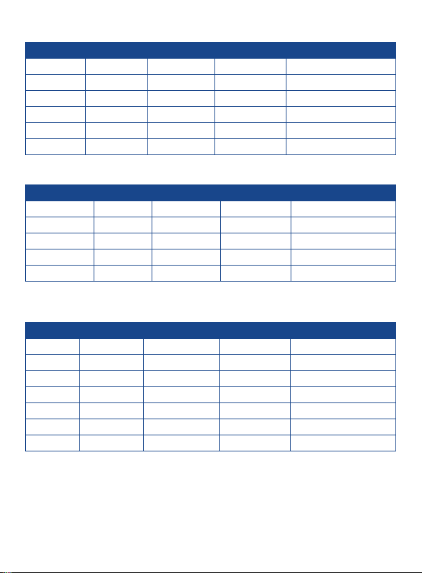
Frequency = 10kHz
Range Resolution Lx Accuracy DF Accuracy Measurement Mode
200.00µH 0.01µH 1.8% ±10d 1.8% ±50d Series
2000.0uH 0.1µH 1.5% ±10d 1.5% ±50d Series
20.000mH 1µH 1.2% ±10d 1.2% ±50d Series
200.00mH 0.01mH 1.5% ±15d 1.5% ±50d ---
2000.0mH 0.1mH 2.0% ±10d 2.0% ±50d Parallel
20.000H 1mH 2.5% ±15d 2.5% ±50d Parallel
Frequency = 100kHz
Range Resolution Lx Accuracy DF Accuracy Measurement Mode
20.000µH 0.001µH 2.5% ±10d 2.5% ±50d Series
200.00µH 0.01µH 1.5% ±10d 1.5% ±50d Series
2000.0µH 0.1µH 1.3% ±15d 1.3% ±50d Series
20.000mH 1µH 2.0% ±15d 2.0% ±50d Parallel
200.00mH 0.01mH 2.5% ±15d 2.5% ±50d Parallel
Capacitance @ Ta = 18 to 28°C (De)
Frequency = 100Hz/120Hz
Range Resolution Cx Accuracy DF Accuracy Measurement Mode
20.000nF 1pF 2.5% ±10d 2.5% ±50d Parallel
200.00nF 0.01nF 1.2% ±10d 1.2% ±50d ---
2000.0nF 0.1nF 0.9% ±10d 0.9% ±50d ---
20.000µF 1nF 1.0% ±15d 1.0% ±50d Series
200.00µF 0.01µF 1.2% ±10d 1.2% ±50d Series
2000.0µF 0.1µF 2.5% ±10d 2.5% ±50d Series
20.00mF 0.01mF 5.0% ±10d 5.0% ±50d Series
www.GlobalTestSupply.com
continued...
7

Frequency = 1kHz
Range Resolution Cx Accuracy DF Accuracy Measurement Mode
2000.0pF 0.1pF 3.5% ±15d 3.5% ±50d Parallel
20.000nF 1pF 1.0% ±10d 1.0% ±50d ---
200.00nF 0.01nF 0.9% ±10d 0.9% ±50d ---
2000.0nF 0.1nF 1.0% ±10d 1.0% ±50d Series
20.000µF 1nF 1.2% ±15d 1.2% ±50d Series
200.00µF 0.01µF 2.5% ±10d 2.5% ±50d Series
2000µF 1µF 4% ±20d 4% ±50d Series
Frequency = 10kHz
Range Resolution Cx Accuracy DF Accuracy
200.00pF 0.01pF 3.0% ±8d 3.0% ±50d Parallel
2000.0pF 0.1pF 1.0% ±10d 1.0% ±50d ---
20.000nF 1pF 0.9% ±10d 0.9% ±50d ---
200.00nF 0.01nF 0.8% ±10d 0.8% ±50d Series
2000.0nF 0.1nF 1.0% ±8d 1.0% ±50d Series
20.000µF 1nF 2.0% ±8d 2.0% ±50d Series
200.0µF 0.1µF 4.5% ±15d 4.5% ±50d Series
Measurement Mode
Frequency = 100kHz
Range Resolution Cx Accuracy DF Accuracy Measurement Mode
200.00pF 0.01pF 2.5% ±15d 2.5% ±50d Parallel
2000.0pF 0.1pF 1.0% ±8d 1.0% ±50d Parallel
20.000nF 1pF 1.8% ±8d 1.8% ±50d Parallel
200.00nF 0.01nF 1.5% ±10d 1.5% ±50d Series
2000.0nF 0.1nF 2.5% ±15d 2.5% ±50d Series
www.GlobalTestSupply.com
continued...
8

Resistance @ Ta = 18 to 28°C (De)
Frequency = 100Hz/120Hz
Range Resolution Rx Accuracy Measurement Mode
200.00Ω 0.01Ω 1.2% ±10d ---
2.0000kΩ 0.1Ω 0.8% ±5d ---
20.000kΩ 1Ω 0.9% ±5d ---
200.00kΩ 0.01kΩ 0.7% ±3d ---
2.0000MΩ 0.1kΩ 1.0% ±5d ---
20.000MΩ 1kΩ 2.2% ±10d ---
200.0MΩ 0.1MΩ 2.5% ±10d ---
Frequency = 1kHz
Range Resolution Rx Accuracy Measurement Mode
20.000Ω 1mΩ 1.2% ±10d ---
200.00Ω 0.01Ω 0.8% ±5d ---
2.0000kΩ 0.1Ω 0.8% ±3d ---
20.000kΩ 1Ω 0.7% ±3d ---
200.00kΩ 0.01kΩ 1.0% ±5d ---
2.0000MΩ 0.1kΩ 1.5% ±10d ---
20.000MΩ 1kΩ 1.8% ±10d ---
200.0MΩ 0.1MΩ 6.0% ±50d ---
Frequency = 10kHz
Range Resolution Rx Accuracy Measurement Mode
20.000Ω 1mΩ 1.5% ±10d ---
200.00Ω 0.01Ω 0.8% ±10d ---
2.0000kΩ 0.1Ω 0.9% ±5d ---
20.000kΩ 1Ω 0.8% ±3d ---
200.00kΩ 0.01kΩ 1.0% ±5d ---
2.0000MΩ 0.1kΩ 2.5% ±10d ---
20.00MΩ 0.01MΩ 2.8% ±10d ---
www.GlobalTestSupply.com
continued...
9

Frequency = 100kHz
Range Resolution Rx Accuracy Measurement Mode
20.000Ω 1mΩ 2.3% ±10d ---
200.00Ω 0.01Ω 1.5% ±5d ---
2.0000kΩ 0.1Ω 0.8% ±20d ---
20.000kΩ 1Ω 0.8% ±20d ---
200.00kΩ 0.01kΩ 1.5% ±10d ---
2.000MΩ 1kΩ 2.5% ±30d ---
DC Resistance @ Ta = 18 to 28°C (De)
Frequency = 100Hz/120Hz/1kHz/10kHz/100KHz
Range Resolution Rx Accuracy Measurement Mode
200.00Ω 0.01Ω 1.8% ±10d ---
2.0000kΩ 0.1Ω 0.6% ±20d ---
20.000kΩ 1Ω 0.6% ±10d ---
200.00kΩ 0.01kΩ 0.5% ±3d ---
2.0000MΩ 0.1kΩ 1.5% ±5d ---
20.000MΩ 1kΩ 2.0% ±5d ---
200.0MΩ 0.1MΩ 2.5% ±5d ---
D Value Accuracy @ Ta =18 to 28°C (De)
Freq./Z 0.1 to 1Ω
100/120Hz ±0.03 ±0.01 0.009 ±0.010 ±0.02 ±0.04
1kHz ±0.03 ±0.01 0.009 ±0.010 ±0.02 ±0.09
10kHz ±0.03 ±0.01 0.009 ±0.009 ±0.01 ±0.04
100kHz ±0.04 ±0.03 0.010 ±0.010 ±0.02 ±0.04
1 to 10Ω
10 to 100kΩ
100k to 1MΩ
1 to 20MΩ
20 to 200MΩ
θ Value Accuracy @ Ta =18 to 28°C
Freq./Z
100/120Hz ±0.65° ±0.36° ±0.23° ±0.45° ±0.65° ±1.35°
1kHz ±0.65° ±0.36° ±0.23° ±0.45° ±0.65° ±3.63°
10kHz ±0.65° ±0.36° ±0.23° ±0.45° ±1.35° N/A
100kHz ±1.27° ±0.65° ±0.49° ±0.65° ±1.35° ±1.35°
0.1 to 1Ω
1 to 10Ω
10 to 100kΩ
100k to 1MΩ
1 to 20MΩ 20 to 200MΩ
www.GlobalTestSupply.com
10

Instrument Description
3
4
5
6
7
8
9
R5001
10
11
12
13
14
15
16
1. LCD Display
2. Function Button
3. Calibration Button
4. Sorting Button
5. Frequency Button
6. Secondary Display/
Left Button
7. Power Button
8. Relative/Down Button
9. Input Sockets
(Banana Jack Inputs) and
Terminals for Positive,
Negative, and Guard
www.GlobalTestSupply.com
10. Setup Button
11. Auto Power Off Button
12. Up Button
13. Enter Button
14. Hold Button
15. Parallel/Series/Right Button
16. Backlight Button
11

Operating Instructions
Power ON/OFF
To turn the meter on or off, press the power button. By default, the meter
is set to Auto LCR Smart mode with a test frequency of 1kHz.
Auto Power Off
To preserve battery life, the meter is programmed to turn off after 5 minutes of
inactivity and 3 warning beeps. If a button is pushed during the three beeps,
the meter will continue measuring. To turn this feature on and off, press the
APO button. When enabled, "APO" will appear on the display.
Beep Function
This meter will beep once if the function selected is available, and beep
twice if the function selected is unavailable.
u = Active Functions
Button FUNC HOLD
AUTOLCR
L
C
ACR
DCR
u u u u
u u u u u u u u
u u u u u u u u
u u u u u u u
u u u u u
Backlight
Press the Backlight Button to turn the backlight on or off. The backlight
will stay on for 60 seconds before turning off automatically.
Battery Charge
The three horizontal bars above the battery symbol on the LCD screen
indicate the charge left in the batteries. When the three bars are no longer
visible the batteries need replacement. See "Battery Replacement" for details.
S/P BKLIT SORT REL% FREQ
DQθ
www.GlobalTestSupply.com
continued...
12

Test Frequency Functions
Test frequency can greatly affect the results of measurement readings,
especially when measuring inductors and capacitors. This section provides
some recommendations and suggestions to consider.
Capacitance
When measuring capacitance, selecting the right frequency is important
in obtaining the most accurate results. Generally a 1kHz test frequency is
used to measure capacitors that are 0.01μF or smaller. For capacitors that
are 10μF or larger, a lower frequency of 120Hz is used. Following this trend,
high-test frequencies are best for testing very low capacitance components.
For large capacitance components, low frequency would be optimal.
For example, if the capacitance of the component is in the mF range, then
selecting 100Hz or 120Hz for the test frequency would give more accurate
results. The results will also be obvious because if the same component
was tested with 1kHz or 10kHz, the measured readings may look erroneous
on the display. In all cases, it is best to check with the manufacturer's data
sheet in order to determine the best test frequency to use for measurement.
Inductance
Typically a 1kHz or 10kHz test frequency is used to measure inductors
that are used in audio and RF circuits because these components operate
at higher frequencies. However, a 120Hz test signal is used to measure
inductors that are used for applications such as lter chokes in power
supplies, which are typically operated at 60Hz AC (in US) with 120Hz
lter frequencies. In general, inductors below 2 mH should be measured
at 1kHz frequency while inductors above 200H should be measured at
120Hz. In all cases, it is best to check with the manufacturer's data sheet
in order to determine the best test frequency to use for measurement.
Selecting Test Frequency
The meter has ve test frequencies: 100Hz/120Hz/1kHz/10kHz/100kHz. Press
the FREQ button to scroll through the ve frequencies sequentially.
Note: The test frequency can affect the accuracy of the results depending
on what frequency is selected as well as what type and value of component
is being measured or tested.
continued...
13
www.GlobalTestSupply.com

Primary Impedance with Secondary Parameter Test
The default test mode for this meter is Auto-LCR Mode, which checks the
type of impedance and automatically enters L/C/R Mode. The secondary
parameter will follow the L/C/R measurement, meaning that (L+Q), (C+D)*,
(R+θ)** are combined in one group respectively.
1. Press the FUNC button to switch from Auto-LCR Mode to Auto-Lp
Mode, Auto-Cp Mode, Auto-Rp Mode, and DCR Mode.
Note: When Auto-Lp or Auto-Cp Mode is selected, the impedance
measurement is auto ranging. The primary LCD display will show the
inductance or capacitance of DUT (device under test); while the secondary
LCD display will show the quality or dissipation factor.
2. Press the button to display the D/Q/θ/ESR value. When Auto-R
(ACR mode) or DCR mode is selected the secondary parameter
is omitted.
* When Auto-LCR mode is active,
Device Under Test Display
the secondary parameter will
show the equivalent resistance in
parallel mode (Rp) to replace the
D factor if the C measured value
of the DUT is less than 5pF.
** Auto-LCR mode only. During
Auto-R Mode or DCR Mode,
the secondary parameter is
not available.
Series or Parallel Functions
Just as test frequency can greatly affect measurement results, selecting
between series or parallel measurement mode can also affect the accuracy
of the meter, especially for capacitive and inductive components. This
section provides some recommendations and suggestions to consider.
www.GlobalTestSupply.com
continued...
14

Capacitance
Most capacitance measurements will obtain best results with parallel mode
selected. The majority of capacitors have a very low dissipation factor
(high internal resistance) compared to the impedance of the capacitance. In
these cases, the paralleled internal resistance has negligible impact on the
measurement. There will be some cases where series mode would be used
for a capacitance measurement, or the readings will appear inaccurate.
Series mode is useful when large capacitors have higher dissipation factor
and lower internal resistance.
Inductance
Most inductance measurements will obtain best results with series mode
selected. In series mode, accurate Q (quality factor) readings can be
obtained from reading low Q inductors and ohmic losses are signicant.
There will be some cases where parallel mode would be used for an
inductance measurement, for example iron core inductors operating at
higher frequencies where hysteresis and eddy currents become signicant.
Series/Parallel Measurements
When any L/C/R function is selected, the default measurement will be
automatically selected. If the impedance is greater than 10kΩ, parallel
mode will be selected, and "Lp/Cp/Rp" will display on the LCD screen. If
the impedance is less than 10kΩ, series mode will be selected, and
"Ls/Cs/Rs" will display on the LCD. When the Parallel/Series/Right Button
is pressed, the impedance measurement will be set in series mode or in
parallel mode sequentially.
Data Hold
1. While taking a measurement, press the HOLD button to freeze the
current readings on the display.
2. While in this mode a "HOLD" symbol will appear.
3. Press the button again to resume normal operation.
Note: When the Data Hold feature is active all buttons except the power &
backlight buttons are disabled.
www.GlobalTestSupply.com
continued...continued...
15

Relative Mode
1. To reserve the current DUT readings (DCUR) on the primary display
as a reference value (DREF), press the button.
2.
The ∆ symbol will then appear on the LCD screen indicating this function
is now active. The secondary display will show the percentage of the
relative value (REL%).
3. Press the button again to show the reference value (DREF) on the
primary display; the ∆ symbol will start to blink.
REL% = (DCUR – DREF) / DREF x 100%
Note: The percentage range is -99.9% to 99.9%. When the relative value
is larger than double the reference value (DREF), the "OL%" symbol will
appear on the secondary display.
4.
Press and hold down the button for approximately 3 seconds to
exit relative mode and resume normal operation.
Accuracy Discrepancies
In some special cases, inaccuracies may occur in the measurement of
capacitive, inductive, and resistive components. This section provides
some recommendations and suggestions to consider.
Capacitance
It is strongly recommended to have the dissipation factor low when measuring
capacitors. Electrolytic capacitors inherently have a higher dissipation factor
due to their normally high internal leakage characteristics. In some cases, if
D (dissipation factor) is excessive, measurement accuracy may degrade and
even read out of specication.
Inductance
Some inductors are intended to operate at a certain DC bias to achieve a
certain inductance value, however this meter cannot produce such a biasing
scheme. External biasing should not be attempted because external power
would be applied to the instrument and cause serious damage to the meter.
Therefore, in some cases, the inductance reading may not agree with
manufacturer's specication. It is important to check if the specication
pertains to DC biasing or not.
www.GlobalTestSupply.com
continued...
16

Resistance
When measuring resistance of devices, it is important to know that there are
two types or ways of measurement. One type is DC resistance measurement.
Another type is AC resistance measurement. The LCR meter provides both
types of measurement.
Before using the meter to measure resistance, please verify whether
the DUT (device under test) requires DC or AC resistance measurement
method. Depending on the method, results will vary greatly.
Guard Terminal
One of the input sockets and terminals is labeled as "GUARD". This
terminal does not have to be used in all instances for the meter to provide
measurements. But in some instances, it is very useful. Guard terminal
generally serves two purposes.
If user is using test leads, the guard terminal can be used to connect to
the shielding of the test leads. Doing so can be useful when making large
resistive component measurements. For example, when measuring a 10
MΩ resistor with test leads, at the high range the reading may seem to be
unstable as a few digits may continuously be changing. Having the shield
of the test leads connected to the guard terminal will help stabilize the
reading in some instances.
Guard terminal is also used to minimize noise and to help minimize parasitic
effects coming from the component being measured, thus allowing high
precision results.
Calibration Mode
It is recommended to regularly calibrate this meter to improve the accuracy
of high/low impedance measurements.
Note: You will need a shorting bar or a short piece of conductive metal
(i.e. paper clip) to complete the calibration procedure.
1. Be sure nothing is connected to the meter, and turn it on.
2. Press and hold down the CAL button for 2 seconds to enter
calibration mode.
3. The screen will display "OPEN", indicating the input terminals have
nothing connected.
continued...
17
www.GlobalTestSupply.com

4. Press the CAL button again and a 30 second countdown will appear
on the screen.
5. After the countdown is complete, a "PASS" or "FAIL" will show on
the display.
6. Press the CAL button a third time, and "SRT" will appear on the LCD
screen, indicating to the user to put the shorting bar across the "+"
and "-" input terminals.
7. Press the CAL button a fourth time, and a 30 second countdown will
appear on the screen.
8.
After the calibration procedure is nished a "PASS" or "FAIL" will appear
on the LCD screen.
9.
Press the CAL button a fth time and the calibration data will be saved
if "PASS" was displayed for both the Open & Short calibrations.
Open Calibration (left) and Short Calibration (right)
Sorting Mode
Sorting mode helps the user quickly sort through multiple components.
Select the primary measurement mode (L/C/R) based on the type of
components to be measured. Insert the component to be used as the
standard or good reference value that will be used for testing against all
other components.
Note: The meter needs a component connected to either the input sockets
or terminals for sorting mode to activate.
1. When ready, turn the meter on and press the SORTING button to
enter sorting mode.
2. The upper display will indicate "PASS" and the lower display will
indicate the value of the component.
Note: The default sorting % is +/- 1%.
continued...
18
www.GlobalTestSupply.com

3. Press the SETUP button and the "Range" symbol will ash on
the display.
4. Adjust the range setting by pressing the or buttons
5. Press the ENTER button save the range setting and proceed to the
value setting.
6. Press the or buttons to select the ashing digit required for
adjustment. Press the or button to adjust the value of the digit.
7. Press the ENTER button to save the value setting and proceed to the
Tolerance setting.
8.
Press the or buttons to scroll through following tolerance % values.
1)
±0.25%
2) ± 0.5%
3) ± 1%
4) ± 2%
9. Press the ENTER button to save the Tolerance setting.
10.
The upper display will now indicate "PASS" or "FAIL", depending on
whether the impedance measured exceeds tolerance range. The current
measurement result will display on the lower display.
11. Press the SORTING Button to exit Sorting Mode.
5) ±5%
6) ±10%
7) ±20%
8) -20% +80%
Battery Replacement
The battery icon indicates the power status of the batteries. As the
batteries weaken, the number of lines will decrease. When the battery icon
appears on the LCD, the batteries must be replaced.
To replace the batteries:
1. Remove the four screws under the ip stand located at the rear of
the meter.
2. Lift up the battery cover and replace the 6 x "AA" batteries
3. Secure the cover back into place with the four screws.
www.GlobalTestSupply.com
19

Accessories and Replacement Parts
• R1210 Alligator Clip Set
• R1020 Fused Test Lead Set
• R8888 Deluxe Hard Carrying Case
• CA-05A Soft Carrying Case
Don't see your part listed here? For a complete list of all accessories and
replacement parts visit your product page on www.reedinstruments.com.
Product Care
To keep your instrument in good working order we recommend the following:
• Store your product in a clean, dry place.
• Change the battery as needed.
• If your instrument isn't being used for a period of one month or longer
please remove the battery.
• Clean your product and accessories with biodegradable cleaner. Do not
spray the cleaner directly on the instrument. Use on external parts only.
www.GlobalTestSupply.com
20

Product Warranty
REED Instruments guarantees this instrument to be free of defects in
material or workmanship for a period of one (1) year from date of shipment.
During the warranty period, REED Instruments will repair or replace, at no
charge, products or parts of a product that proves to be defective because
of improper material or workmanship, under normal use and maintenance.
REED Instruments total liability is limited to repair or replacement of the
product. REED Instruments shall not be liable for damages to goods,
property, or persons due to improper use or through attempts to utilize the
instrument under conditions which exceed the designed capabilities. In
order to begin the warranty service process, please contact us by phone at
1-877-849-2127 or by email at info@reedinstruments.com to discuss the
claim and determine the appropriate steps to process the warranty.
Product Disposal and Recycling
Please follow local laws and regulations when disposing or recycling your
instrument. Your product contains electronic components and must be
disposed of separately from standard waste products.
www.GlobalTestSupply.com
21

Product Support
If you have any questions on your product, please contact your authorized
REED distributor or REED Instruments Customer Service by phone at
1-877-849-2127 or by email at info@reedinstruments.com.
Please visit www.REEDINSTRUMENTS.com for the most
up-to-date manuals, datasheets, product guides and software.
Product specifications subject to change without notice.
All rights reserved. Any unauthorized copying or reproduction of
this manual is strictly prohibited without prior written permission
from REED Instruments.
www.GlobalTestSupply.com
22

TEST & MEASURE
WITH CONFIDENCE
CHECK OUT OUR LATEST PRODUCTS!
www.GlobalTestSupply.com

www.GlobalTestSupply.com
 Loading...