

Page 1
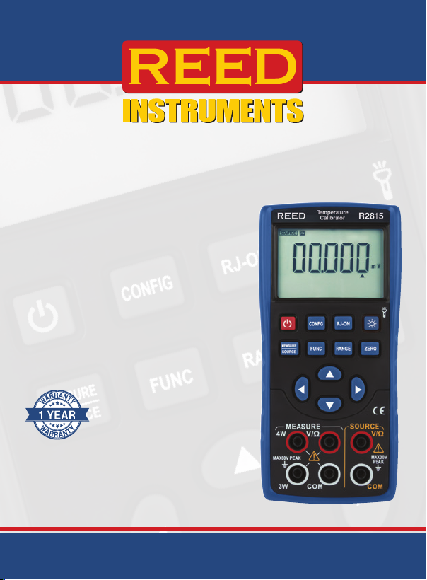
Temperature
Calibrator
Instruction
Manual
R2815
1-877-849-2127 | [email protected] | www.reedinstruments.com
REED Instruments
Page 2

Table of Contents
Introduction ................................................................................................ 4
Product Quality ........................................................................................... 4
Safety ......................................................................................................... 4
Features ...................................................................................................... 5
Included ...................................................................................................... 5
Specications ........................................................................................ 5-11
Measure Functions..............................................................................5-7
Source Functions .............................................................................. 8-10
General Specifications ......................................................................... 11
Instrument Description ........................................................................ 12-13
Input and Output Terminals .................................................................. 13
Display Description .................................................................................. 14
Operating Instructions .............................................................................. 15
Power ON/OFF .................................................................................... 15
Auto Power-Off .................................................................................... 15
Backlight .............................................................................................. 15
Output Function ..................................................................................16-19
Connecting Leads to Output Terminals ............................................... 16
Outputting DC Voltage ....................................................................16-17
Analog Output Resistance ................................................................... 17
Analog Output Thermocouple.........................................................17-18
Analog Output Thermal Resistance ..................................................... 19
Reset Function ......................................................................................... 20
Measurement Mode ............................................................................20-24
Connecting Leads to Input Terminals ............................................. 20-22
Measuring DC Voltage ......................................................................... 22
Measuring Resistance ..................................................................... 22-23
Measuring Thermocouples .............................................................23-24
Measuring Thermal Resistance ............................................................ 24
continued...
1-877-849-2127 | [email protected] | www.reedinstruments.com
REED Instruments
Page 3

Factory Settings Adjustment ............................................................... 25-26
Accessing the Settings ........................................................................ 25
Enabling/Disabling Auto Power OFF .................................................... 25
Setting Backlight Time ......................................................................... 25
Setting Flashlight Time ......................................................................... 26
Enabling/Disabling the Beeper Sound ................................................. 26
Selecting the Temperature Unit of Measure ........................................ 26
Factory Reset ........................................................................................... 27
Battery Replacement ................................................................................ 28
Applications .............................................................................................. 28
Accessories and Replacement Parts ....................................................... 29
Product Care ............................................................................................ 29
Product Warranty ..................................................................................... 30
Product Disposal and Recycling .............................................................. 30
Product Support ....................................................................................... 30
REED Instruments
1-877-849-2127 | [email protected] | www.reedinstruments.com
Page 4

Introduction
Thank you for purchasing your REED R2815 Temperature Calibrator.
Please read the following instructions carefully before using your
instrument. By following the steps outlined in this manual your meter will
provide years of reliable service.
Product Quality
This product has been manufactured to meet the stated product
specications. If a certicate of calibration is required please contact the
nearest authorized REED distributor or authorized Service Center. Please
note an additional fee for this service will apply.
Safety
Never attempt to repair or modify your instrument. Dismantling your
product, other than to replace batteries, may cause damage that will not
be covered under the manufacturer's warranty. Servicing should only
be provided by an authorized service center. To avoid injury to the user
or damage to the instrument, please read the safety information below
before initial use:
• Do not operate the instrument around ammable or explosive gas,
vapor or dust.
• Never apply more than 30V between any two terminals, or between any
terminal and ground terminal.
Note: For optimal accuracy, allow the instrument to warm up 5 minutes
before operating. If the automatic reference-junction temperature
compensation of the instrument deviates from its designed accuracy,
contact an Authorized REED Service Center.
1-877-849-2127 | [email protected] | www.reedinstruments.com
REED Instruments
4
Page 5

Features
• Accurately sources and measures 11 thermocouple types, including A,
B, C, D, E, J, K, N, R, S, T
• Supports 5 RTD (3-wire) types, including Pt100, Pt200, Pt500, Pt1000
and Cu50
• Source and measure Volts and Ohms
• Internal cold junction compensation for improved accuracy
• Easy to read 6-digit LCD display
• Zero adjustment button
• Built-in LED ashlight
• User selectable unit of measure (°F/°C)
• Low battery indicator and auto shut off
Included
• Temperature Calibrator
• Test Leads
• Alligator Clips
• Thermocouple Adapter
• Batteries
Specifications
Measure Function
Measurement Range
DCV
OHM
1-877-849-2127 | [email protected] | www.reedinstruments.com
100mV -110 to 110.00mV 0.01mV 0.05% rdg. +30mV
30V -30 to 30V 0.001V 0.02% rdg. +2mV
500Ω 0 to 500Ω 0.01Ω 0.05% rdg. +0.2Ω
5KΩ 0 to 5KΩ 0.0001KΩ 0.05% rdg. +2Ω
Measurement
Range
1V -1.1 to 1.1V 0.0001V 0.05% rdg. +0.3mV
Resolution Accuracy
continued...
REED Instruments
5
Page 6
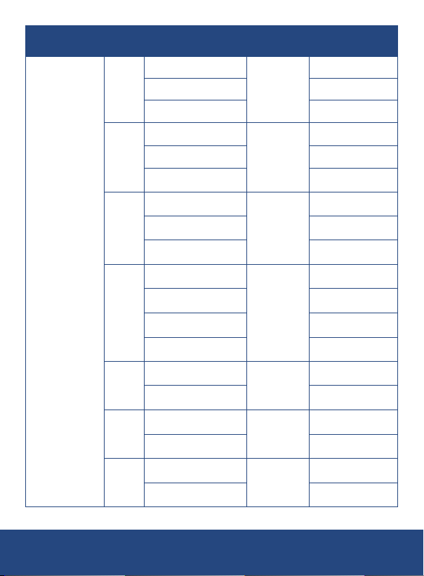
Measurement Range
TC
Measurement
Range
0 to 2912°F
(0 to 1600°C)
2912 to 3632°F
A
(1600 to 2000°C)
3632 to 4532°F
(2000 to 2500°C)
1112 to 1472°F
(600 to 800°C)
1472 to 1832°F
B
(800 to 1000°C)
1832 to 3308°F
(1000 to 1820°C)
0 to 2912°F
0 to 1600°C)
2912 to 3632°F
C
(1600 to 2000°C)
3632 to 4190°F
(2000 to 2310°C)
0 to 212°F
(0 to 100°C)
212 to 518°F
D
E
J
K
(100 to 270°C)
518 to 2192°F
(270 to 1200°C)
2192 to 4190°F
(1200 to 2310°C)
-58 to 32°F
(-50 to 0°C)
32 to 1832°F
(0 to 1000°C)
-76 to 32°F
(-60 to 0°C)
32 to 2192°F
(0 to 1200°C)
-148 to 32°F
(-100 to 0°C)
32 to 2501.6°F
(0 to 1372°C)
REED Instruments
Resolution Accuracy
±3.6°F (2.0°C)
1°F (1°C)
1°F (1°C)
1°F (1°C)
1°F (1°C)
0.1°F (0.1°C)
0.1°F (0.1°C)
0.1°F (0.1°C)
±4.0°F (2.2°C)
±4.3°F (2.4°C)
±4.0°F (2.2°C)
±3.2°F (1.8°C)
±2.5°F (1.4°C)
±3.6°F (2.0°C )
±4.0°F (2.2°C)
±4.3°F (2.4°C)
±4.7°F (2.6°C)
±4.3°F (2.4°C)
±4.0°F (2.2°C)
±4.3°F (2.4°C)
±1.6°F (0.9°C)
±2.7°F (1.5°C)
±1.8°F (1.0°C)
±1.3°F (0.7°C)
±2.1°F (1.2°C)
±1.4°F (0.8°C)
continued...
6
1-877-849-2127 | [email protected] | www.reedinstruments.com
Page 7
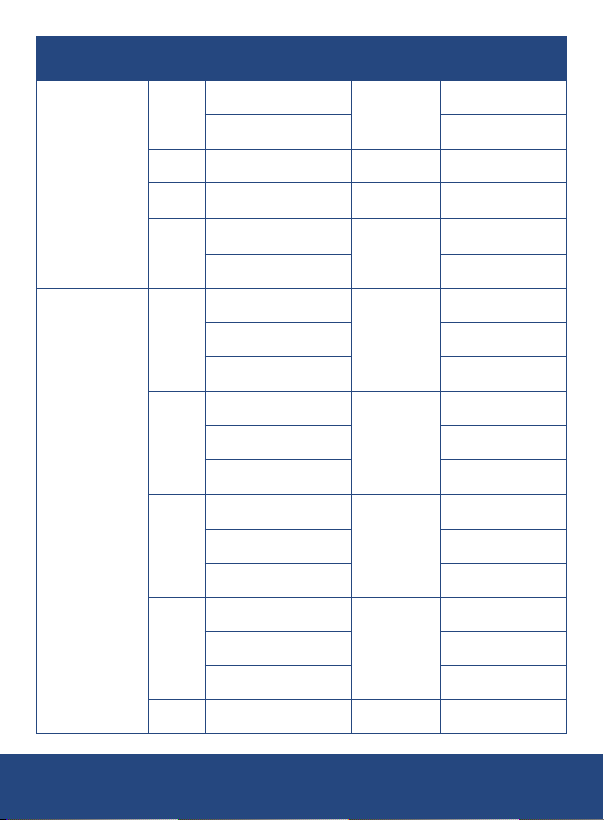
Measurement Range
TC
Pt100
385
Pt200
385
RTD
(3-Wire)
Pt500
385
Pt1000
385
Cu50
Measurement
Range
-328 to 32°F
N
R
S
T
(-200 to 0°C)
32 to 2372°F
(0 to 1300°C)
0 to 3212.6°F
(0 to 1767°C)
0 to 3212.6°F
(0 to 1767°C)
-148 to 32°F
(-100 to 0°C)
32 to 752°F
(0 to 400°C)
-328 to 32°F
(-200 to 0°C)
32 to 752°F
0 to 400°C)
752 to 1472°F
(400 to 800°C)
-328 to 212°F
(-200 to 100°C)
212 to 572°F
(100 to 300°C)
572 to 1166°F
(300 to 630°C)
-328 to 212°F
(-200 to 100°C)
212 to 572°F
(100 to 300°C)
572 to 1166°F
(300 to 630°C)
-328 to 212°F
(-200 to 100°C)
212 to 572°F
(100 to 300°C)
572 to 1166°F
(300 to 630°C)
-58 to 302°F
(-50 to 150°C)
REED Instruments
Resolution Accuracy
0.1°F (0.1°C)
1°F (1°C) ±4.5°F (2.5°C)
1°F (1°C) ±3.6°F (2.0°C )
0.1°F (0.1°C)
0.1°F (0.1°C)
0.1°F (0.1°C)
0.1°F (0.1°C)
0.1°F (0.1°C)
0.1°F (0.1°C) ±1.3°F (0.7°C)
±2.7°F (1.5°C)
±1.6°F (0.9°C)
±1.8°F (1.0°C)
±1.3°F (0.7°C)
±0.9°F (0.5°C)
±1.3°F (0.7°C)
±1.4°F (0.8°C)
±1.4°F (0.8°C)
±1.6°F (0.9°C)
±1.8°F (1.0°C)
±0.7°F (0.4°C)
±0.9°F (0.5°C)
±1.3°F (0.7°C)
±0.5°F (0.3°C)
±0.9°F (0.5°C)
±1.3°F (0.7°C)
continued...
7
1-877-849-2127 | [email protected] | www.reedinstruments.com
Page 8
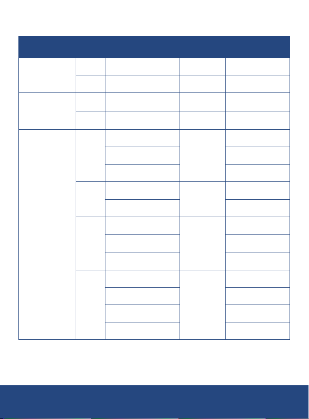
Source Function
Output Range Output Range Resolution Accuracy
100mV -10 to 110mV 0.01mV
DCV
1V -0.1 to 1.1V 0.0001V 0.05% rdg. +0.3mV
0.05% rdg.
+0.03mV
OHM
TC
400Ω 0 to 400Ω 0.1Ω 0.05% rdg. +0.2Ω
4KΩ 0 to 4KΩ 1Ω 0.05% rdg. +2Ω
1°F (1°C)
1°F (1°C)
1°F (1°C)
1°F (1°C)
±3.6°F (2.0°C )
±4.0°F (2.2°C)
±4.3°F (2.4°C)
±2.7°F (1.5°C)
±2.0°F (1.1°C)
±3.6°F (2.0°C )
±4.0°F (2.2°C)
±4.3°F (2.4°C)
±4.7°F (2.6°C)
±4.3°F (2.4°C)
±4.0°F (2.2°C)
±4.3°F (2.4°C)
continued...
A
B
C
D
0 to 2912°F
(0 to 1600°C)
2912 to 3632°F
(1600 to 2000°C)
3632 to 4532°F
(2000 to 2500°C)
1112 to 1472°F
(600 to 800°C)
1472 to 3308°F
(800 to 1820°C)
0 to 2912°F
(0 to 1600°C)
2912 to 3632°F
(1600 to 2000°C)
3632 to 4190°F
(2000 to 2310°C)
0 to 212°F
(0 to 100°C)
212 to 518°F
(100 to 270°C)
518 to 2192°F
(270 to 1200°C)
2192 to 4190°F
(1200 to 2310°C)
REED Instruments
8
1-877-849-2127 | [email protected] | www.reedinstruments.com
Page 9
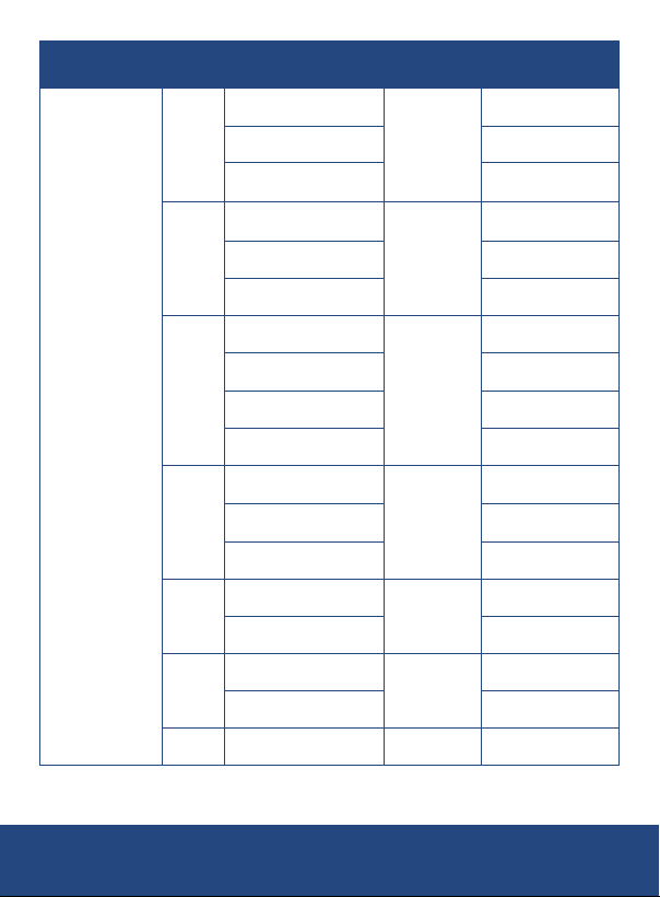
Output Range Output Range Resolution Accuracy
TC
E
J
K
N
R
S
T
-328 to -148°F
(-200 to -100°C)
-148 to 1112°F
(-100 to 600°C)
1112 to 1832°F
(600 to 1000°C)
-328 to -148°F
(-200 to -100°C)
-148 to 1472°F
(-100 to 800°C)
1472 to 2192°F
(800 to 1200°C)
-328 to -148°F
(-200 to -100°C)
-148 to 752°F
(-100 to 400°C)
-752 to 2192°F
(-400 to 1200°C)
-2192 to 2501°F
(-1200 to 1372°C)
-328 to -148°F
(-200 to -100°C)
-148 to 1652°F
(-100 to 900°C)
1652 to 2372°F
(900 to 1300°C)
0 to 212°F
(0 to 100°C)
212 to 3212°F
(100 to 1767°C)
0 to 212°F
(0 to 100°C)
212 to 3212°F
(100 to 1767°C)
-418 to 752°F
(-250 to 400°C)
0.1°F (0.1°C)
0.1°F (0.1°C)
0.1°F (0.1°C)
0.1°F (0.1°C)
1°F (1°C)
1°F (1°C)
0.1°F (0.1°C) ±0.5°F (0.6°C)
±0.5°F (0.6°C)
±0.9°F (0.5°C)
±0.7°F (0.4°C)
±0.5°F (0.6°C)
±0.9°F (0.5°C)
±1.3°F (0.7°C)
±0.5°F (0.6°C)
±0.9°F (0.5°C)
±1.3°F (0.7°C)
±1.6°F (0.9°C)
±1.8°F (1.0°C)
±1.3°F (0.7°C)
±1.4°F (0.8°C)
±2.7°F (1.5°C)
±2.1°F (1.2°C)
±2.7°F (1.5°C)
±2.1°F (1.2°C)
continued...
REED Instruments
9
1-877-849-2127 | [email protected] | www.reedinstruments.com
Page 10
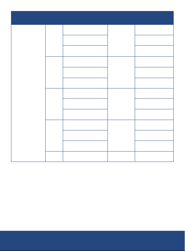
Output Range Output Range Resolution Accuracy
RTD
(3-Wire)
Pt100
385
Pt200
385
Pt500
385
Pt1000
385
Cu50
-328 to 32°F
(-200 to 0°C)
32 to 752°F
(0 to 400°C)
752 to 1472°F
(400 to 800°C)
-328 to 212°F
(-200 to 100°C)
212 to 572°F
(100 to 300°C)
572 to 1166°F
(300 to 630°C)
-328 to 212°F
(-200 to 100°C)
212 to 572°F
(100 to 300°C)
572 to 1166°F
(300 to 630°C)
-328 to 212°F
(-200 to 100°C)
212 to 572°F
(100 to 300°C)
572 to 1166°F
(300 to 630°C)
-58 to 302°F
(-50 to 150°C)
0.1°F (0.1°C)
0.1°F (0.1°C)
0.1°F (0.1°C)
0.1°F (0.1°C)
0.1°F (0.1°C) ±0.5°F (0.6°C)
±0.5°F (0.3°C)
±0.9°F (0.5°C)
±1.4°F (0.8°C)
±1.4°F (0.8°C)
±1.6°F (0.9°C)
±1.8°F (1.0°C)
±0.7°F (0.4°C)
±0.9°F (0.5°C)
±1.3°F (0.7°C)
±0.5°F (0.2°C)
±0.9°F (0.5°C)
±1.3°F (0.7°C)
1-877-849-2127 | [email protected] | www.reedinstruments.com
REED Instruments
10
Page 11

General Specifications
Display: 6-Digit LCD
Backlit Display: Yes
Kick Stand: Yes
Magnetic Hanger Compatible: Yes (R5900 sold separately)
Built-In Flashlight: Yes
Zero Adjustment Button: Yes
Power Supply: 3 AA Batteries
Battery Life: Approx. 20 hours
Cold Junction
Compensation: Yes
Auto shut off: Yes (up to 60 minutes/off)
Low Battery Indicator: Yes
Replaceable Test Leads: Yes
Product Certications: CE
Operating Temperature: 32 to 122°F (0 to 50°C)
Operating Humidity Range: 0 to 85%
Storage Temperature: 14 to 122°F (-10 to 50°C)
Dimensions: 7.5 x 3.5 x 2.1" (191 x 90 x 53mm)
Weight: 17.6oz (500g)
1-877-849-2127 | [email protected] | www.reedinstruments.com
REED Instruments
11
Page 12
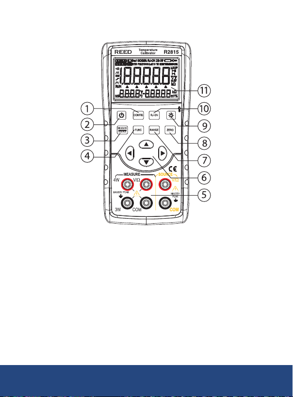
Instrument Description
Red
Red
Black
1. CONFIG button
2. Power Button
3. MEASURE/SOURCE Button
4. Function Button
5. Input/Output Terminals
6. Output Selection/Setting Buttons
7. RANGE Button
8. ZERO Button
9. Backlight/Flashlight Button
10. RJ-ON Button
11. LCD Display
REED Instruments
1-877-849-2127 | [email protected] | www.reedinstruments.com
12
Page 13
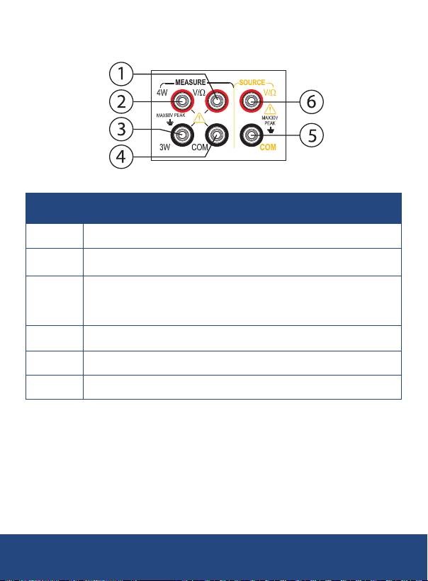
Input and Output Terminals
Terminal Function Description
1 VΩ terminal: Input terminal for all measurement (+)
4W terminal: 4-wire resistance measurement
2
high-end SENSE
3W terminal:
3
4-wire resistance measurement low-end SENSE
3-wire resistance measurement SENSE terminal
4 COM terminal: Common (-) (return) terminal for all inputs
5 COM terminal: Common (-) (return) terminal for all inputs
6 VΩ terminal: Output terminal for all outputs (+)
1-877-849-2127 | [email protected] | www.reedinstruments.com
REED Instruments
13
Page 14
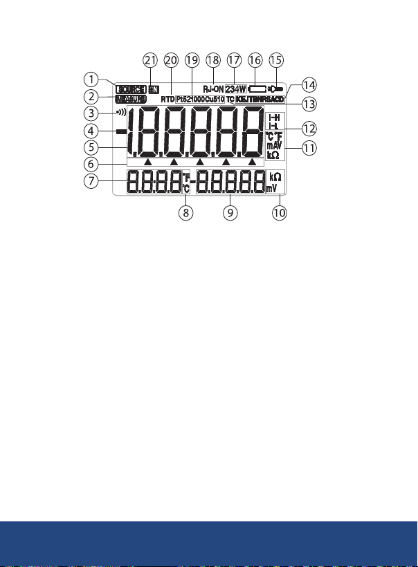
Display Description
1.
Source Mode Indicator
2. Measure Mode Indicator
3. Function Status Indicator
4. Input/Output Value
Polarity Indicator
5. Input/Output Value
6. Selected Digit Indicator
7. Cold-End Compensation
Temperature Value
8. Cold-End Compensation
Temperature Unit of Measure
9. Voltage/Resistance
Measurement Value
10. Voltage/Resistance Unit
of Measure
11. Input/Output Unit of Measure
12. Output Resistance
Excitation Indicator
13. Thermocouple
Function Indicator
14. Thermocouple
Range Indicator
15. Flashlight Indicator
16. Battery Status Indicator
17. Input Resistance/
Thermal Resistance
Wire System Indicator
18. Cold Junctions
Compensation Indicator
19. Thermal Resistance
Range Indicator
20. Thermal Resistance
Function Indicator
21. Signal Connection Indicator
1-877-849-2127 | [email protected] | www.reedinstruments.com
REED Instruments
14
Page 15

Operating Instructions
Power ON/OFF
Press the Power button to turn the instrument on. To turn the instrument
off, press and hold the Power button.
Auto Power-Off
As a default, the instrument will automatically turn off after 5 minutes of
inactivity. To turn off this feature, refer to the "Enabling/Disabling Auto
Power OFF" section of this manual for additional details.
Backlight
Press the Backlight button to turn the LCD Backlight on or off.
Note: The backlight automatically turns off after approximately 60
seconds by default. To turn it back on, press the Backlight button. The
backlight illumination duration can be adjusted in the factory settings.
For more information, refer to the "Setting Backlight Time" section of this
manual for additional details.
1-877-849-2127 | [email protected] | www.reedinstruments.com
REED Instruments
15
Page 16
Output Function
The output terminal of the instrument can produce DC voltages or can
simulate thermocouple temperature set by the user.
To avoid electric shock, ensure that the voltage applied between the
calibrator terminals or between any terminal and ground does not
exceed the rated voltage specied for the calibrator. Do not use the
calibrator in situations where the terminal-to-ground voltage exceeds
30V peak.
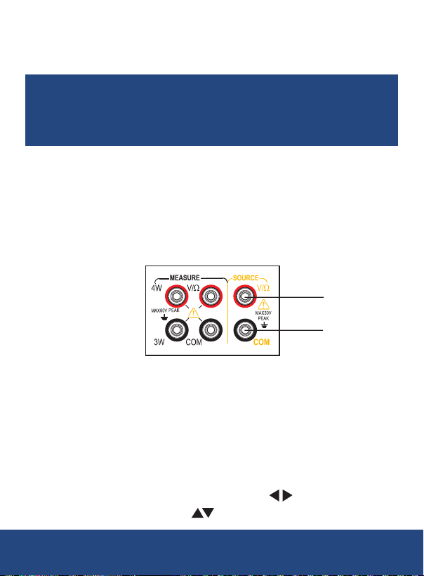
Connecting Leads to Output Terminals
Connection method for all outputs:
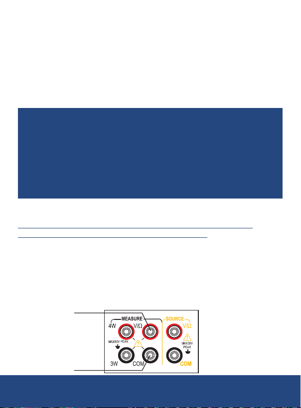
1. Connect the black lead to the COM terminal and the red lead to the
V/Ω terminal of the output.
2. Attach the opposite ends of the leads to the input terminals of the
controlled device, ensuring that the terminal polarities are correct.
Red
Black
Outputting DC Voltage
1. Press the MEASURE/SOURCE button to switch to the output mode.
The SOURCE indicator will illuminate on the display. By default, the
calibrator will be in DC voltage mode with an initial measurement
range of 100mV. The "mV" symbol on the right side of the main
display will light up.
2. Press the RANGE button to select the desired measurement range
(options: 100mV, 1V).
3. Set the output value using the output setting buttons:
• Change the digit to be adjusted using the
• Adjust the value using the buttons.
REED Instruments
1-877-849-2127 | [email protected] | www.reedinstruments.com
buttons.
continued...
16
Page 17

Note: Press the ZERO button to reset the output setting to the default
value (0).
Analog Output Resistance
1. Press the FUNC button to switch to the analog resistance function.
The "Ω" symbol on the right side of the main display will light up,
indicating resistance mode.
2. Press the RANGE button to select the desired measurement range
(400Ω / 4KΩ).
Note: For the 400Ω range, two excitation currents are available: 1mA
and 0.1mA. You can manually switch between them to improve accuracy
based on your needs.
To set the excitation current:
• Press the CONFIG button to enter the excitation current setting
menu. "OHM.IS" will appear in the secondary display area at the
lower right corner.
• The main display area will show "I-H" for 1mA or "I-L" for 0.1mA.
• Use the
• Press the ZERO button to save the setting.
• Press CONFIG button to exit the setting menu.
3. Set the output value using the output setting buttons:
• Change the digit to be adjusted using the
• Adjust the value using the buttons.
Note: If the excitation current does not match the selected range (400Ω), the
excitation current indicator on the right side of the display will flash. In this case,
return to the setting interface to adjust the excitation current appropriately.
buttons to select the excitation current.
buttons.
Analog Output Thermocouple
1.
Press the FUNC button to switch to the thermocouple (TC) function.
The "TC" indicator in the upper right corner of the display will light up.
2. Press the RANGE button to select the desired thermocouple type (R,
S, K, E, J, T, N, B, A, C, D).
3. If cold junction compensation is required, press RJ-ON to activate
the cold junction compensation function. If not, skip this step.
REED Instruments
1-877-849-2127 | [email protected] | www.reedinstruments.com
continued...
17
Page 18
There are two types of cold junction compensation:
Automatic: The instrument uses its internal temperature sensor to detect
the ambient temperature automatically.
Manual: The user sets the cold junction compensation temperature
manually.
To set cold junction compensation:
• Press the CONFIG button to enter the cold junction compensation
settings menu. "RJST" will appear in the secondary display area at
the lower right corner.
• The main display will show "MANU" for manual compensation or
"AUTO" for automatic compensation.
• Use the
automatic compensation.
• Press the ZERO button to save the setting.
• If manual compensation is selected, you will be prompted to set the
manual temperature. The secondary display will show "RJVA," and
the main display will show the temperature to be set. Use the
to 50°C.
• Press the ZERO button to save the setting.
• Press CONFIG button to exit the setting menu.
Note: In automatic cold junction compensation, the current ambient
temperature will be displayed in the lower-left corner of the screen.
In manual cold junction compensation, the user-set compensation
temperature will be displayed, and the "M" symbol will light up.
4. Set the output value using the output setting buttons:
• Change the digit to be adjusted using the
• Adjust the value using the
buttons to switch between manual and
buttons to adjust the temperature within the range of -10°C
buttons.
buttons.
continued...
1-877-849-2127 | [email protected] | www.reedinstruments.com
REED Instruments
18
Page 19
Analog Output Thermal Resistance
1.
Press the FUNC button to switch to the analog thermal resistance
output function. The "RTD" indicator in the upper left corner of the
display will light up.
2. Press the RANGE button to select the desired thermal resistance
type (PT100, PT200, PT500, PT1000, Cu50).
For PT100 and Cu50 divisions, two excitation currents are available (1mA
and 0.1mA). The user can switch between them for more accurate thermal
resistance simulation.
To set the excitation current:
• Press the CONFIG button to enter the excitation current setting
interface. "OHMI.S" will appear in the secondary display area at the
lower right corner.
• The main display will show "I-H" for 1mA or "I-L" for 0.1mA.
• Use the
• Press the ZERO button to save the setting.
• Press CONFIG button to exit the setting menu.
3. Set the output value using the output setting buttons:
• Change the digit to be adjusted using the
• Adjust the value using the
Note: For PT100 and Cu50 divisions, if the selected excitation current
does not match the required value, the excitation current indicator on the
right side of the display will flash. You will need to re-enter the setting
interface to adjust the excitation current accordingly.
buttons to select the desired excitation current.
buttons.
buttons.
1-877-849-2127 | [email protected] | www.reedinstruments.com
REED Instruments
19
Page 20
Reset Function
Red
Red
Black
• Press the ZERO button to perform a reset operation in any
measurement range of the DC voltage, resistance, thermocouple, or
thermal resistance output functions.
•
This action will reset the output setting value to the default initial value,
providing a convenient way for users to quickly return to the starting point.
Measurement Mode
Warning: When using the calibrator in measurement mode, ensure
that all connections are made with the proper leads. The maximum
allowable voltage between any input terminal and ground is 60V peak.
Exceeding this limit may result in electric shock. Never apply a voltage
higher than this maximum to the terminal or ground.
If the measured value exceeds the allowable measurement range, the
"OL" (Overload) symbol will appear in the main display area, indicating
that the input is out of range.
Connecting Leads to Input Terminals
Connection Method for DC Voltage, Thermocouple, Thermal
Resistance, and Resistance (2W) Measurement:
1. Connect the black lead to the COM terminal of the input.
2. Connect the red lead to the VΩ terminal of the input.
3. Attach the other ends of the two leads to the measurement terminals
of the device under test.
4. Ensure that the terminal polarity is correct to ensure
accurate measurements.
Black
REED Instruments
1-877-849-2127 | [email protected] | www.reedinstruments.com
continued...
20
Page 21
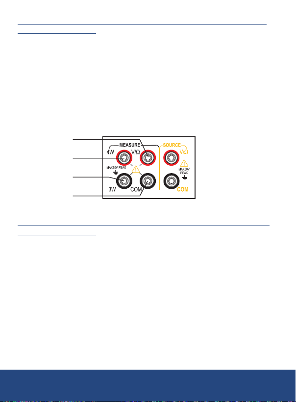
Connection Method for Resistance (3W) and Thermal Resistance
Red
Red
Red
Black
Black
(3W) Measurement:
1. Connect the black lead to the COM terminal of the input.
2. Connect the red lead to the VΩ terminal of the input.
3. Connect the third lead to the 3W terminal.
4. Attach the other ends of the three leads to the measurement
terminals of the device under test, ensuring that each lead is
connected correctly.
5. Verify that the terminal polarity is correct to ensure
accurate measurements.
4W
3W
Black
Connection Method for Resistance (4W) and Thermal Resistance
Measurement (4W):
1. Connect the black lead to the COM terminal of the input.
2. Connect the red lead to the VΩ terminal of the input.
3. Connect the third lead to the 3W terminal.
4. Connect the fourth lead to the 4W terminal.
5. Attach the other ends of the four leads to the measurement terminals
of the device under test.
6. Ensure that each lead is connected to the correct terminal and verify
that the terminal polarity is correct to ensure
accurate measurements.
continued...
1-877-849-2127 | [email protected] | www.reedinstruments.com
REED Instruments
21
Page 22

Warning: Disconnect Power Supply: Before connecting the calibrator
to the device under test, ensure that the device's power supply
is disconnected.
Avoid Damage and Injury: Incorrect operation or measurement can
potentially damage the instrument or cause injury. Exercise extreme
caution and follow proper procedures during all measurement operations
.
Measuring DC Voltage
1. Ensure that the measurement lead is disconnected from the device
under test.
2. Press the MEASURE/SOURCE button to switch to measurement
mode. The MEASURE indicator will light up on the display screen.
By default, the calibrator will be set to DC voltage function with a
measurement range of 100mV. The "mV" symbol will appear on the
right side of the main display area.
3. Press the RANGE button to select the desired measurement range
(100mV, 1V, 30V).
4. Connect the measurement lead to the device under test. The
measured voltage value will be displayed in the main display area.
Measuring Resistance
1. Ensure that the measurement lead is disconnected from the device
under test.
2. Press the FUNC button to switch to the resistance function. The "Ω"
symbol will light up on the display screen.
3. Press the RANGE button to select the desired measurement range
(500Ω or 5KΩ).
4. Set the resistance wire system:
• Press the CONFIG button to enter the wire system setting
interface. The secondary display area at the lower right corner will
show "Wire System"
• The main display area will show the available wire systems
(2W, 3W, 4W).
• Use the
1-877-849-2127 | [email protected] | www.reedinstruments.com
buttons to select the desired excitation current.
continued...
REED Instruments
22
Page 23

• Press the ZERO button to save the setting.
• Press CONFIG button to exit the setting menu.
5. Connect the measurement lead to the measurement terminals of the
device under test. The measured resistance value will be displayed in
the main display area.
Measuring Thermocouples
1. Ensure that the measurement lead is disconnected from the device
under test.
2. Press the FUNC button to switch to the thermocouple function. The
"TC" symbol will light up on the display screen.
3. Press the RANGE button to select the required thermocouple type
(R, S, K, E, J, T, N, B, A, C, D).
4. If cold junction compensation is required, press the RJ-ON button
to enable this function. If cold junction compensation is not required,
skip this step.
Setting Cold Junction Compensation:
• Automatic Temperature Compensation: The instrument uses its
internal temperature sensor to detect the ambient
temperature automatically.
• Manual Temperature Compensation: The user sets the
compensation temperature manually.
To set the excitation current:
•
Press the CONFIG button to enter the cold junction compensation
setting interface. "RJST" will appear in the secondary display area at
the lower right corner, indicating the compensation method settings
• The main display will show "MANU" for manual temperature
compensation or "AUTO" for automatic temperature compensation.
• Use the buttons to select the desired excitation current.
• Press the ZERO button to save the setting.
• Press CONFIG button to exit the setting menu.
.
continued...
1-877-849-2127 | [email protected] | www.reedinstruments.com
REED Instruments
23
Page 24

Note:
• For automatic cold junction compensation, the actual ambient
temperature will be displayed in the lower-left corner of the screen.
• For manual compensation, the user-set compensation temperature
will be displayed with the "M" symbol lit.
5. Connect the measurement lead to the measurement terminals of the
device under test. The measured value will be displayed in the main
display area.
Measuring Thermal Resistance
1. Ensure that the measurement lead is disconnected from the device
under test.
2. Press the FUNC button to switch to the thermal resistance function.
The "RTD" symbol will light up on the display screen.
3. Press the RANGE button to select the desired thermal resistance
type (PT100, PT200, PT500, PT1000, Cu50).
4. Set the thermal resistance wire system:
• Press the CONFIG button to enter the wire system setting
interface. "WRIE" will be displayed in the lower right corner of the
screen.
• The main display will show the available wire systems
(2W, 3W, 4W).
• Use the buttons to select the appropriate wire system.
• Press the ZERO button to save the setting.
• Press CONFIG button to exit the setting menu.
5. Connect the measurement lead to the measurement terminals of the
device under test. The measured value will be displayed in the main
display area.
1-877-849-2127 | [email protected] | www.reedinstruments.com
REED Instruments
24
Page 25
Factory Settings Adjustment
Follow the steps below to access and change the default calibrator settings.
Accessing the Settings
1. Press and hold the Backlight button.
2. While holding the Backlight button, press the Power button to turn
on the instrument.
3. Once the settings interface appears, release the Backlight button.
Enabling/Disabling Auto Power OFF
1. Upon entering the settings interface, "APOF" will appear on the
display, indicating the automatic shutdown setting.
2. Use the buttons to adjust the automatic shutdown time
between 0 and 60 minutes. A setting of 0 disables the automatic
shutdown; other values represent the time in minutes after which the
instrument will shut down.
3. Press the ZERO button to conrm selection. The display will show
"SAVE," conrming that the new setting has been saved.
Note: You can turn the meter OFF and then back ON at any time to
resume normal operation.
Setting Backlight Time
1. Press the CONFIG button until "BLOF" appears on the display,
indicating the backlight time setting.
2. Use the buttons to adjust the backlight time setting
between 0 and 3600 seconds. A setting of 0 disables the automatic
backlight shutdown; other values represent the time in seconds after
which the backlight will turn off.
3. Press the ZERO button to conrm selection. The display will show
"SAVE," conrming that the new setting has been saved.
Note: You can turn the meter OFF and then back ON at any time to
resume normal operation.
1-877-849-2127 | [email protected] | www.reedinstruments.com
REED Instruments
25
Page 26
Setting Flashlight Time
1. Press the CONFIG button until "LTOF" appears on the display,
indicating the ashlight time setting.
2. Use the buttons to set the desired ashlight time settings
between 0-30 minutes. A setting of 0 disables the automatic
ashlight shutdown; other values represent the time in minutes after
which the ashlight will turn off.
3. Press the ZERO button to conrm selection. The display will show
"SAVE," conrming that the new setting has been saved.
Note: You can turn the meter OFF and then back ON at any time to
resume normal operation.
Enabling/Disabling the Beeper Sound
1. Press the CONFIG button until "BEEP" appears on the display,
indicating the buzzer setting.
2. Use the buttons to toggle between ON (Enabled) or
OFF (Disabled).
3. Press the ZERO button to conrm selection. The display will show
"SAVE," conrming that the new setting has been saved.
Note: You can turn the meter OFF and then back ON at any time to
resume normal operation.
Selecting the Temperature Unit of Measure
1. Press the CONFIG button until "TEPU" appears on the display,
indicating the temperature unit setting.
2. Use the buttons to select between °C and °F.
3. Press the ZERO button to conrm selection. The display will show
"SAVE," conrming that the new setting has been saved.
Note: You can turn the meter OFF and then back ON at any time to
resume normal operation.
1-877-849-2127 | [email protected] | www.reedinstruments.com
REED Instruments
26
Page 27

Factory Reset
1. Press the CONFIG button until the display shows "FACT" to enter
the factory default settings.
Factory Default Settings:
APOF(AutoPowerO):5minutes
BLOF(BacklightO):60seconds
LTOF (Light Timeout): 5 minutes
BEEP: ON
TEPU (Temperature Unit): °C
2. Use the
Note:
NO: The settings will remain as they are and will not be restored to
factory defaults.
YES: All settings will be restored to factory default settings.
3. Press the ZERO button to conrm selection.
Note: You can turn the meter OFF and then back ON at any time to
resume normal operation.
buttons to select between YES and NO.
1-877-849-2127 | [email protected] | www.reedinstruments.com
REED Instruments
27
Page 28
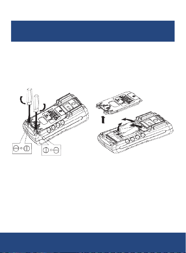
Battery Replacement
Warning: To prevent electric shock, always remove the test leads from
the calibrator before opening the battery compartment. Ensure the
battery door is securely closed before using the calibrator.
1. Turn off the calibrator and remove the test leads.
2. Use a athead screwdriver to turn the battery door screws a quarter
turn counterclockwise and remove the door.
3. Replace the 3 x AA batteries in the battery compartment.
4. Close the battery door and securely tighten the screws.
Applications
• Ideal for calibrating devices that use thermocouples as input signals
(e.g., meters, controllers, transmitters, data loggers,
and recorders)
• Essential for applications requiring precise thermocouple temperature
measurements, including:
- Chemical production
- Petroleumreneries
- Manufacturing
- Power production
- Steel and iron industries
1-877-849-2127 | [email protected] | www.reedinstruments.com
REED Instruments
28
Page 29

Accessories and Replacement Parts
R2920 Surface Thermocouple Probe
R2930 Right Angle Thermocouple Probe
R2940 Air/Gas Thermocouple Probe
R2950 Immersion Thermocouple Probe
R2960 Needle Tip Thermocouple Probe
R2970 Type K Pipe Clamp Thermocouple Probe
R2980 Type K Air Oven/Freezer Thermocouple Probe
TP-01 Type K Beaded Wire Probe
CA-05A Soft Carrying Case
R9940 Hard Shell Carrying Case
R1000 Safety Test Lead SetW
R1020 Fused Test Lead Set
R5900 Magnetic Meter Strap
Don't see your part listed here? For a complete list of all accessories and
replacement parts visit your product page on www.REEDInstruments.com.
Product Care
To keep your instrument in good working order we recommend the following:
• Store your product in a clean, dry place.
• Change the battery as needed.
• If your instrument isn't being used for a period of one month or longer
please remove the battery.
• Clean your product and accessories with biodegradable cleaner. Do not
spray the cleaner directly on the instrument. Use on external parts only.
1-877-849-2127 | [email protected] | www.reedinstruments.com
REED Instruments
29
Page 30
Product Warranty
REED Instruments guarantees this instrument to be free of defects in
material or workmanship for a period of one (1) year from date of shipment.
During the warranty period, REED Instruments will repair or replace, at no
charge, products or parts of a product that proves to be defective because
of improper material or workmanship, under normal use and maintenance.
REED Instruments total liability is limited to repair or replacement of the
product. REED Instruments shall not be liable for damages to goods,
property, or persons due to improper use or through attempts to utilize the
instrument under conditions which exceed the designed capabilities. In
order to begin the warranty service process, please contact us by phone at
1-877-849-2127 or by email at [email protected] to discuss the
claim and determine the appropriate steps to process the warranty.
Product Disposal and Recycling
Please follow local laws and regulations when disposing or recycling your
instrument. Your product contains electronic components and must be
disposed of separately from standard waste products.
Product Support
If you have any questions on your product, please contact your authorized
REED distributor or REED Instruments Customer Service by phone at
1-877-849-2127 or by email at [email protected].
Please visit www.REEDInstruments.com for the most
up-to-date manuals, datasheets, product guides and software.
Product specifications subject to change without notice.
All rights reserved. Any unauthorized copying or reproduction of
this manual is strictly prohibited without prior written permission
from REED Instruments.
1-877-849-2127 | [email protected] | www.reedinstruments.com
REED Instruments
30
Page 31

TEST & MEASURE
WITH CONFIDENCE
CHECK OUT OUR LATEST PRODUCTS!
www.REEDInstruments.com
1-877-849-2127 | [email protected] | www.reedinstruments.com
REED Instruments
Page 32

www.REEDInstruments.com
1-877-849-2127 | [email protected] | www.reedinstruments.com
REED Instruments
 Loading...