


Temperature
Simulator
R2800
Instruction
Manual
www.GlobalTestSupply.com

Table of Contents
Introduction ................................................................................................ 3
Product Quality ........................................................................................... 3
Safety ......................................................................................................... 3
Features ...................................................................................................... 4
Included ...................................................................................................... 4
Specications .......................................................................................... 4-6
Output Functions ................................................................................4-5
General Specifications ........................................................................... 6
Instrument Description ............................................................................... 7
Display Description .................................................................................... 8
Operating Instructions ........................................................................... 8-12
Power ON/OFF ...................................................................................... 8
Auto Power-Off ...................................................................................... 9
Output Function ..................................................................................... 9
Simulating Output from DC Voltage ..................................................9-10
Simulating Output from Thermocouple (TC) ................................... 10-11
Simulating output from thermal resistance or RTD ......................... 11-12
Battery Replacement ................................................................................ 12
Applications .............................................................................................. 13
Accessories and Replacement Parts ....................................................... 13
Product Care ............................................................................................ 13
Product Warranty ..................................................................................... 13
Product Disposal and Recycling .............................................................. 14
Product Support ....................................................................................... 14
www.GlobalTestSupply.com
2

Introduction
Thank you for purchasing your REED R2800 Temperature Simulator. Please
read the following instructions carefully before using your instrument. By
following the steps outlined in this manual your meter will provide years of
reliable service.
Product Quality
This product has been manufactured to meet the stated product specications.
If a certicate of calibration is required please contact the nearest authorized
REED distributor or authorized Service Center. Please note an additional fee for
this service will apply.
Safety
Never attempt to repair or modify your instrument. Dismantling your
product, other than for the purpose of replacing batteries, may cause
damage that will not be covered under the manufacturer's warranty.
Servicing should only be provided by an authorized service center. To
avoid injury to the user or damage to the instrument, please read the
safety information below before initial use:
• Do not operate the instrument around ammable or explosive gas,
vapor or dust.
• Never apply more than 30V between any two terminals, or between any
terminal and ground terminal.
Note: For optimal accuracy, allow the instrument to warm up 5 minutes
before operating. If the automatic reference-junction temperature
compensation of the instrument deviates from its designed accuracy,
contact an Authorized REED Service Center.
www.GlobalTestSupply.com
3

Features
• Source 8 thermocouple types, including R, S, B, E, K, J, T, N; and 7
RTD types, including Pt 10 (385), Pt100 (385), Pt200 (385), Pt500 (385),
Pt1000 (385), Cu10, Cu50; plus volts and ohms
• Basic accuracy of 0.05%
• Internal cold junction compensation
• Easy-to-read 6-digit LCD display
• Zero adjustment button
• User selectable unit of measure (°F/°C)
• Low battery indicator and auto shut off
Included
• Test Leads
• Alligator Clips
• Thermocouple Adapter
• Protective Holster
• Batteries
Specifications
Output Functions
Accuracy specied at 23°C ±5°C & 75% RH for a period of one year
after calibration.
Output Range Output Range Resolution Accuracy
DCV
OHM
100mV -10.00 to 110.00mV 0.01mV 0.05% rdg. + 30mV
1000mV -100.00 to 1100.00mV 0.1mV 0.05% rdg. + 0.3mV
400Ω 0.0 to 400.0Ω 0.1Ω ±0.05% rdg. + 0.2Ω
400Ω 0 to 4000Ω 1Ω ±0.05% rdg. + 2Ω
www.GlobalTestSupply.com
continued...
4

Output Range Output Range Resolution Accuracy
R -40 to 1760°C 1°C
S -20 to 1760°C 1°C
B 400 to 1800°C 1°C
TC
RTD
E -200.0 to 1000.0°C 0.1°C
K -200.0 to 1370.0°C 0.1°C
J -200.0 to 1200.0°C 0.1°C
T -200.0 to 400.0°C 0.1°C
N -200.0 to 1300.0°C 0.1°C
Cu10 -10.0 to 250.0°C 0.1°C
Cu50 -50.0 to 150°C 0.1°C
Pt10 385 -200.0 to 850°C 0.1°C
Pt100 385 -200.0 to 850°C 0.1°C
Pt200 385 -200.0 to 630°C 0.1°C
Pt500 385 -200.0 to 630°C 0.1°C
Pt1000 385
-200.0 to 630°C 0.1°C
±0.05% rdg. +3°C
(≤100°C) ±0.05% rdg.
+2°C (>100°C)
±0.05% rdg. +3°C
(400 to 600°C);
±0.05% rdg. +2°C
(>600°C)
±0.05% rdg. +2°C
(≤-100°C) ±0.05%
rdg. +1°C (>-100°C)
±0.05% rdg. +0.6°C
±0.05% rdg. +0.6°C
±0.05% rdg. +0.6°C
Notes
• Excludes accessory lead resistance
• Range of excitation current: 0.5mA to 3mA; Max. output voltage: ≤2V
•
The accuracies indicated do not include the error of internal temperature
compensation caused by a sensor. The range of the internal temperature
compensation sensor is from -10 to 50°C with its compensating error up
to 0.5°C.
www.GlobalTestSupply.com
continued...
5

General Specifications
Display: 6-Digit LCD
Zero Adjustment Button: Yes
Kick Stand: Yes
Power Supply: 2 x AA Batteries
Cold Junction Compensation: Yes
Auto Shut Off: Yes (after 15 minutes/off)
Low Battery Indicator: Yes
Replaceable Test Leads: Yes
Product Certications: CE
Operating Temperature: 32 to 122°F (0 to 50°C)
Operating Humidity Range: 0 to 85%
Storage Temperature: 14 to 122°F (-10 to 50°C)
Dimensions: 7.1 x 3.5 x 1.9" (180 x 90 x 47mm)
Weight: 8.2oz (500g)
www.GlobalTestSupply.com
6

Instrument Description
R2800
OUTPUT
Pt1000 Pt200 Pt500 Cu50 Cu10
1
2
3
4
SIMULATOR
RJ-ON
Ω°C°F
mV
5
6
7
8
9
10
1. LCD Display
2. ON/OFF Button
3. °C/°F Selection Button
4. RJ-ON Button (T/C Reference Junction Compensation Button)
5. Function Selection Output Button
6. Range Selection Button
7. Zero Reset Button
8. Output Value Setting Button
9.
Output Digit Selection Button
10. Output Terminals
www.GlobalTestSupply.com
7
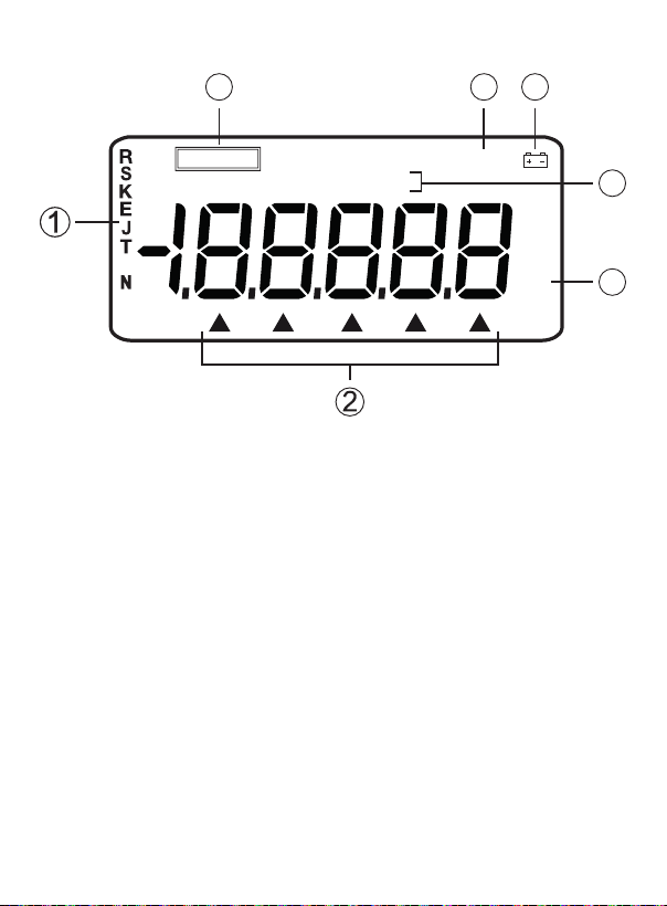
Display Description
567
OUTPUT
Pt1000 Pt200 Pt500 Cu50 Cu10
B
1. Thermocouple Type Indicator
2. Indicates which output value is being set
3. Current output value (unit of measure)
4. RTD Type Indicator
5. Low Battery Indicator
6. Instrument is performing its reference-cold junction compensation
7. Output State Indicator
RJ-ON
Ω°C°F
mV
4
3
Operating Instructions
Power ON/OFF
Press the POWER button to turn the instrument on. Press and hold the
POWER button to turn the instrument off. When the instrument is on, it
will begin an internal self-diagnosis at which time the full screen will be
displayed. When complete, the instrument is ready to take measurements.
www.GlobalTestSupply.com
continued...
8

Auto Power-Off
As a default the instrument will automatically turn off after 15 minutes of
inactivity. To turn off this feature:
1. Turn the meter off.
2. Press the POWER button (to display the full screen).
3. Quickly press the RANG button when the instrument is in the
maintenance state as indicated by "1.8.8.888".
4. "AP-XX" will now appear on the display.
5. Press the button to toggle between "AP-ON" & "AP-OF". "AP-OF"
indicates that the no automatic power-off function is disabled, while
"AP-ON" indicates the automatic power-off function is enabled.
6. Press the ZERO button to save the required setting.
7. Press and hold the POWER button to exit the maintenance state and
turn the instrument off.
Output Function
• The output terminal of the instrument can produce DC voltages set by
the user or can simulate resistance.
Do not apply any voltage to the output terminal during the operation.
If any improper voltage is applied to the output terminal, it will cause
damage to the internal circuit.
Simulating Output from DC Voltage
1. Insert one end of the test lead into
the output (TC/mV) jack of the
meter and connect the other end
to the input of the instrument under
test, as shown in the diagram to
the right.
2. Press the FUNC button to select
"DC Voltage Output". "V" will
appear on the display.
www.GlobalTestSupply.com
continued...
9

3. Press the RANG button to select the range of 1.0000V or 100.00mV.
"V" or "mV" will appear on the display.
4. Press the and buttons to move the on-screen cursor in order to
select the desired digit on the display.
5. Press the and buttons to change the numerical value of each
digit. (Numerical value cannot be changed beyond range maximum.)
6. Press the ZERO button and the output will be set to 00.00mV
or 0.0000V.
Simulating Output from Thermocouple (TC)
1. Insert one end of the test lead into the output (TC/mV) jack of the
meter and connect the other end to the input of the instrument under
test, as shown in the above diagram.
2.
Press the FUNC button to select "Thermocouple Output". "R" and
"°C" will appear on the display.
3. Press the RANG button to select the type of thermocouple.
4. Press the and buttons to move the on-screen cursor in order to
select the desired digit on the display.
5. Press the and buttons to change the numerical value of each
digit. (Numerical value cannot be changed beyond range maximum.)
6. Automatic compensation for reference-junction temperature.
7. Press the ZERO button and the output will be directly set to 0000°C
(R or S type), 400°C (B type) or 0000.0°C (other type).
8. Press the °C/°F button to select the unit °C or °F.
Note: During the direct calibration of an instrument with reference-junction
temperature compensation, it is recommended to press the RJ-ON button
so that the instrument can start the function of automatic referencejunction compensation. Thus providing the required thermo-electromotive
force for output followed by displaying the symbol "RJ-ON" where:
Output thermoelectric force = corresponding emf of set
temperature – emf of room temperature
•
It takes two seconds for the instrument to start its internal referencejunction
temperature. After this, each automatic compensation occurs at
10 second intervals.
continued...
10
www.GlobalTestSupply.com
• If there is a change in the operating ambient temperature, do not start
the operation until the built-in compensating sensor has become stable
(approx. 10 minutes).
• If there is no need for the simulator to perform the function of automatic
reference-junction compensation, press the RJ-ON button and the
symbol "RJ-ON" will no longer appear in the display.
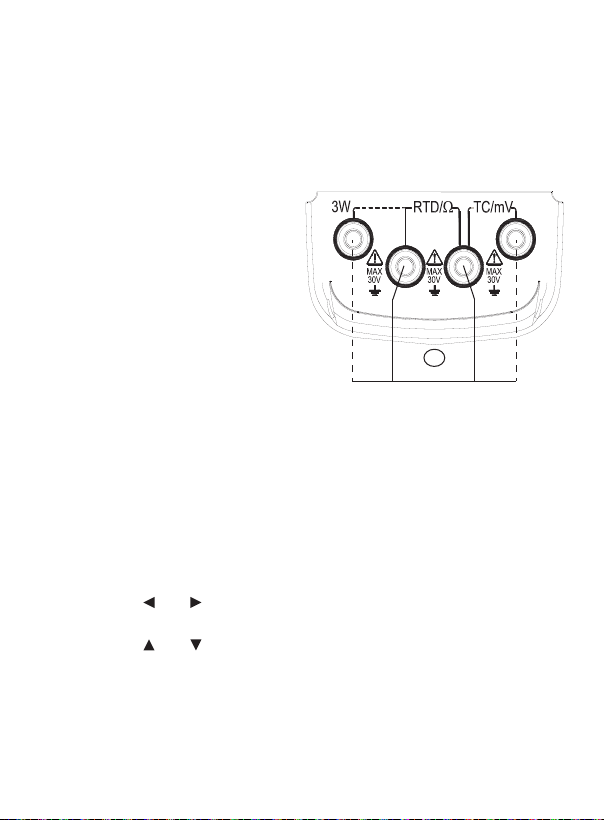
Simulating output from thermal resistance or RTD
1. Insert one end of the test lead
into the output (RTD/Ω) jack
of the meter and connect
the other end to the input of
the instrument under test as
shown in the diagram to the
right. The dedicated test leads
supplied with the simulator are
intended for a 2-wire system
for testing output according to
RTD
2w
user's requirement.
Note: An additional set of test leads are required for 3-wire or
4-wire systems.
2. The display of the symbol "OUTPUT" denotes the instrument is in an
output state.
3. Press the FUNC button to select thermal resistance output or RTD
output as indicated by "Ω" or "°C" and "Cu10" (Copper 10 ohm RTD)
on the LCD display.
4. While RTD function is selected, press the RANG button to select the
type of RTD.
5. Press the
and buttons to move the on-screen cursor in order to
select the desired digit on the display.
6. Press the and buttons to change the numerical value of each
digit. (Numerical value cannot be changed beyond range maximum.)
7. Press the ZERO button and the output will be directly set to 000.0°C.
8. Press the °C/°F button to select the unit °C or °F.
4w3w
www.GlobalTestSupply.com
continued...
11
Note: The instrument produces a simulation resistance up to 400Ω at
its output terminal (RTD /Ω). The method of simulating resistance output
is to send out an appropriate voltage 'Vx' according to the excitation
current 'Ix' produced by the calibrated instrument. Because R (set
resistance) = Vx (output voltage) / Ix (excitation current), the calibrated
device must provide an excitation current tothe simulator. The excitation
current should range from 0.5mA to 2mA.
Note:
When testing the resistance output of a 4-wire system while
employing a 2-wire connection, you should take into consideration the
error (approx. 0.1Ω) arising from the lead resistance of the test leads. If
the capacitance between the resistance output terminal of the simulator
and the tested instrument is more than 0.1μf, the simulator will produce
improper resistance.
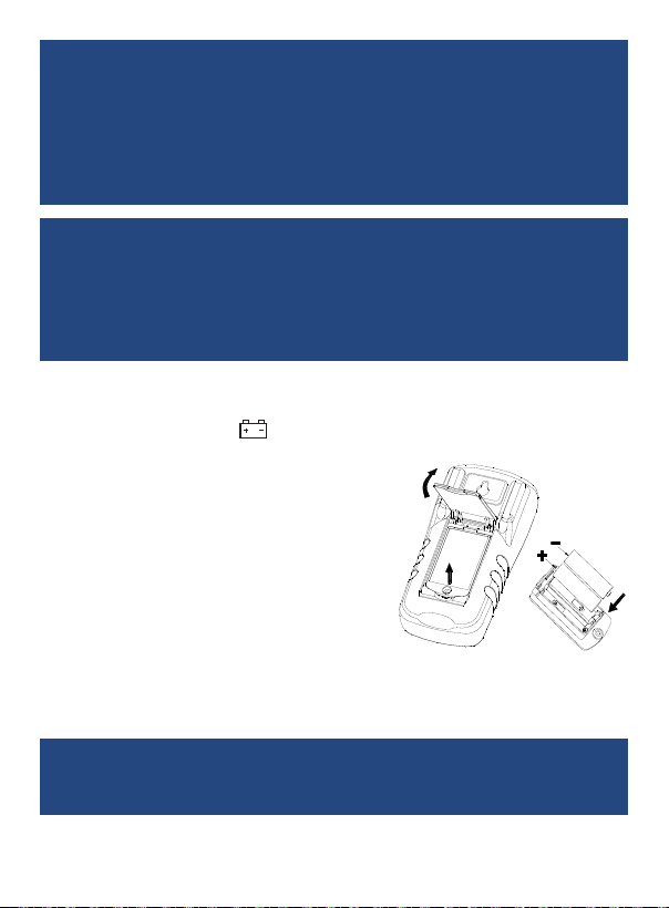
Battery Replacement
When the battery symbol, , appears on the display, the battery needs to
be replaced. In order to replace the battery, proceed with the following steps.
1. Ensure that the meter is turned OFF
and remove any test leads from the
meter's terminals.
2. Lift the tilt stand on the back of the unit
to access the battery compartment
door which can be removed using a
Phillips head screwdriver.
3. Replace the 2 x AA batteries in the lid
of the battery compartment.
4. Reinstall the compartment lid by ensuring that battery terminals
touch the unit's contact points and snap into place.
5. Tighten the screw to secure the battery compartment cover.
Note: Ensure battery door is closed and secured in place before using
the meter. To ensure proper operation, please wait 5 seconds before
turning meter on after changing batteries.
www.GlobalTestSupply.com
12

Applications
• Verication and calibration of temperature instruments including
thermocouple and RTD thermometers.
Accessories and Replacement Parts
R2920 Surface Thermocouple Probe
R2930 Right Angle Thermocouple Probe
R2940 Air/Gas Thermocouple Probe
R2950 Immersion Thermocouple Probe
R2960 Needle Tip Thermocouple Probe
CA-05A Soft Carrying Case
R9940 Hard Shell Carrying Case
AD-1 Thermocouple Adapter
R1000 Safety Test Lead
FC-300 Fused Test Lead Set
Don't see your part listed here? For a complete list of all accessories and
replacement parts visit your product page on www.reedinstruments.com.
Product Care
To keep your instrument in good working order we recommend the following:
• Store your product in a clean, dry place.
• Change the battery as needed.
• If your instrument isn't being used for a period of one month or longer
please remove the battery.
• Clean your product and accessories with biodegradable cleaner. Do not
spray the cleaner directly on the instrument. Use on external parts only.
www.GlobalTestSupply.com
13

Product Warranty
REED Instruments guarantees this instrument to be free of defects in
material or workmanship for a period of one (1) year from date of shipment.
During the warranty period, REED Instruments will repair or replace, at no
charge, products or parts of a product that proves to be defective because
of improper material or workmanship, under normal use and maintenance.
REED Instruments total liability is limited to repair or replacement of the
product. REED Instruments shall not be liable for damages to goods,
property, or persons due to improper use or through attempts to utilize the
instrument under conditions which exceed the designed capabilities. In
order to begin the warranty service process, please contact us by phone at
1-877-849-2127 or by email at info@reedinstruments.com to discuss the
claim and determine the appropriate steps to process the warranty.
Product Disposal and Recycling
Please follow local laws and regulations when disposing or recycling your
instrument. Your product contains electronic components and must be
disposed of separately from standard waste products.
Product Support
If you have any questions on your product, please contact your authorized
REED distributor or REED Instruments Customer Service by phone at
1-877-849-2127 or by email at info@reedinstruments.com.
Please visit www.REEDInstruments.com for the most
up-to-date manuals, datasheets, product guides and software.
Product specifications subject to change without notice.
All rights reserved. Any unauthorized copying or reproduction of
this manual is strictly prohibited without prior written permission
from REED Instruments.
www.GlobalTestSupply.com
14

TEST & MEASURE
WITH CONFIDENCE
CHECK OUT OUR LATEST PRODUCTS!
www.GlobalTestSupply.com

www.GlobalTestSupply.com
 Loading...