


Model
Pantone 534 Blue
Pantone 123 Yellow
Pantone 485 Red
Pantone 123 Yellow
Pantone 534 Blue
Black
MS2301
Ground Resistance
Clamp Meter
Instruction
Manual
www
reedinstruments
www.GlobalTestSupply. com
com

Pantone 534 Blue
Pantone 123 Yellow
Pantone 485 Red
Pantone 123 Yellow
Pantone 534 Blue
Black
Rich Black -
20/20/20/100
Blue - 100/80/30/5
Yellow - 0/27/100/0
Red - 10/100/100/5
Yellow - 0/27/100/0
Blue - 100/80/30/5
Table of Contents
Safety .......................................................................................................3
Maintenance .............................................................................................3
Features ....................................................................................................4
Specications ........................................................................................4-5
Instrument Description/Function ...........................................................6-7
LCD Display ...........................................................................................8-9
Operating Instructions .......................................................................10-14
On/Off ..................................................................................................................10
Ground Resistance Measurement .......................................................................10
Schematics of Measurement ......................................................................... 11-12
Current Measurement .........................................................................................12
Alarm Operation ..................................................................................................13
Memory ......................................................................................................... 13-14
Special Functions ................................................................................................14
Battery Replacement .............................................................................. 15
Field Applications ..............................................................................16-18
For service on this or any other REED product or for information on other
REED products, contact REED Instruments at info@reedinstruments.com
www
www
www.GlobalTestSupply. com
reedinstruments
reedinstruments
com
com
2
2

Pantone 534 Blue
Pantone 123 Yellow
Pantone 485 Red
Pantone 123 Yellow
Pantone 534 Blue
Black
Rich Black -
20/20/20/100
Blue - 100/80/30/5
Yellow - 0/27/100/0
Red - 10/100/100/5
Yellow - 0/27/100/0
Blue - 100/80/30/5
Safety
To ensure safe operation and service of this meter, follow these instructions:
• Before use take note that the metal objects and the conductors of
this meter can be very dangerous
• When testing the meter, pay extra attention to safety to prevent
shock and arc blast injury where hazardous live conductors are
exposed
• Before each use, inspect the meter; look for cracks or missing portions of the housing or output cable insulation as well as loose or
weakened components, pay particular attention to the insulation
surrounding the jaws
• Operating limits of Unit are as indicated on the back of the Meter
(600V in Category III)
• Use extreme caution when working around bare conductors or busbars, contact with the conductor could result in electric shock
• Before turning the instrument on, press the trigger several times to
ensure the jaw is closing correctly
• When the meter is on and auto-calibrating, do not open the jaw or
hook it around any conductor
Maintenance
• Keep the surfaces of the jaw clean, any dirt can cause malfunctions
• Use a soft damp cloth to clean the jaw faces, do not use abrasives,
solvents or alcohol
• Avoid any shocks to the meter, especially to the jaw faces
• After each measurement, press the HOLD button to save battery
power
• Remove the batteries from the meter if not to be used for a prolonged period of time
www
www.GlobalTestSupply. com
reedinstruments
com
3

Pantone 534 Blue
Pantone 123 Yellow
Pantone 485 Red
Pantone 123 Yellow
Pantone 534 Blue
Black
Rich Black -
20/20/20/100
Blue - 100/80/30/5
Yellow - 0/27/100/0
Red - 10/100/100/5
Yellow - 0/27/100/0
Blue - 100/80/30/5
Features
This ground resistance clamp meter is more advanced than
the traditional testers.
• Supplementary leads and other accessories are not required
• Measure ground resistance safely and quickly by simply clamping
the ground line
• Measure current as well as resistance
• Resolution of 0.001Ω
• Accuracy of ± 0.01Ω for low resistance measurements
• Stores up to 99 resistance measurements
• Resistance limit alarm function
• User selectable alarm threshold from 1 to 100Ω
• Measures leakage current to 1mA and neutral current to 20A
• 1secondsamplingtime•Display“Hold”•Auto-ranging
• Doubly insulated conductor clamp
• Large jaws open to 45 x 32mm
Specifications
Range Accuracy Resolution
0.01-0.999Ω ±(1.5% +0.01Ω) 0.001Ω
1-9.99Ω ±(1.5% +0.1Ω) 0.01Ω
10-99.9Ω ±(2.0% +0.3Ω) 0.1Ω
Resistance:
Current:
100-199.9Ω ±(3.0% +1Ω) 1Ω
200-400Ω ±(6.0% +5Ω) 5Ω
400-600Ω ±(10% +10Ω) 10Ω
600-1200Ω approx. 20% 20Ω
100mA ±(2.5% +1mA) 0.1mA
300mA ±(2.5% +2mA) 0.3mA
1A ±(2.5% +0.003A) 0.001A
3A ±(2.5% +0.01A) 0.003A
10A ±(2.5% +0.03A) 0.01A
20A ±(2.5% +0.05A) 0.03A
www
www.GlobalTestSupply. com
reedinstruments
com
4

Pantone 534 Blue
Pantone 123 Yellow
Pantone 485 Red
Pantone 123 Yellow
Pantone 534 Blue
Black
Rich Black -
20/20/20/100
Blue - 100/80/30/5
Yellow - 0/27/100/0
Red - 10/100/100/5
Yellow - 0/27/100/0
Blue - 100/80/30/5
Testing Conditions:
Temperature: 23°C ±3°C
Humidity: 50% RH ±10%
Battery Voltage: >7V
External Magnetic Field: <40A/m
External Electric Field: <1 V/m
Testing Frequency of Current: 45 Hz to 65 Hz
Operating Temperature: -10°C to 50°C (14°F to 122°F)
Storage Temperature: -20°C to 60°C (-4°F to 140°F)
Max. Test Voltage: 3700V
Overload Protection: 20A rms
Electric Clearance: 6.5mm
(IEC1010 double insulation,CAT II 600V)
Electric Shock: IEC1010-1
Display: 4-digit LCD, 9999 counts
Power Supply: 1 x 9V battery
Battery Life: 10 to 12 hours of continuous use
Dimensions: 54 x 104 x 276mm
Weight: 1050g (with battery)
Includes: 3 resistance calibration loops (1Ω, 5Ω,
and 10Ω), hard carrying case,
batteries, and display cleaning wipe
www
www.GlobalTestSupply. com
reedinstruments
com
5

Pantone 534 Blue
Pantone 123 Yellow
Pantone 485 Red
Pantone 123 Yellow
Pantone 534 Blue
Black
Rich Black -
20/20/20/100
Blue - 100/80/30/5
Yellow - 0/27/100/0
Red - 10/100/100/5
Yellow - 0/27/100/0
Blue - 100/80/30/5
Instrument Description/Function
www
www.GlobalTestSupply. com
reedinstruments
com
6

Pantone 534 Blue
Pantone 123 Yellow
Pantone 485 Red
Pantone 123 Yellow
Pantone 534 Blue
Black
Rich Black -
20/20/20/100
Blue - 100/80/30/5
Yellow - 0/27/100/0
Red - 10/100/100/5
Yellow - 0/27/100/0
Blue - 100/80/30/5
Description Button Function
1 Jaws
2 Trigger
3 MEM Button
Select/Set Memory Mode
4 Power Button ON/OFF/EXIT Set Mode
5 LCD Display
6 AL Button Select Alarm Mode
ARROW Ω
7
Button
ARROW A
8
Button
Ω Measurement/Alarm
Value Decrease/Record
Number Select
A Measurement/Alarm Value
Increase/Record Number Select
9 HOLD Button HOLD Display
Additional
Functions
+
+
+
+
+
www
reedinstruments
www.GlobalTestSupply. com
Switch Buzzer ON/OFF
Set Alarm Value
Auto Power Off Function Set
Read Saved Measurement Value
Reset Memory to Zero
com
7
Pantone 534 Blue
Pantone 123 Yellow
Pantone 485 Red
Pantone 123 Yellow
Pantone 534 Blue
Black
Rich Black -
20/20/20/100
Blue - 100/80/30/5
Yellow - 0/27/100/0
Red - 10/100/100/5
Yellow - 0/27/100/0
Blue - 100/80/30/5
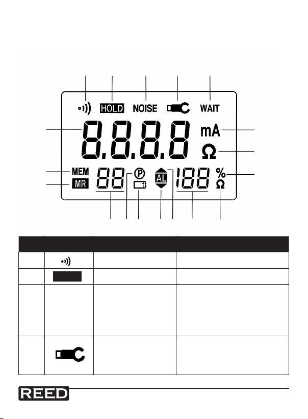
LCD Display
Note: When the meter is turned on, it performs a rapid auto-test of the
entire display. All the symbols will show in the display for a short time.
1 2 3 4 5
18
6
7
17
8
16
11
1415
1213
Symbol Description Function
1 Buzzer The buzzer is ON
2 Hold Holds the last measurement
3 Interference Symbol
4 Clamp
HOLD
NOISE
www
www.GlobalTestSupply. com
reedinstruments
10
9
Indicates that the current
in the grounding loop has
been disturbed. The
resistance measurement
can be affected
Indicates that the jaws
are not closed properly,
the meter will not take
measurements
continued ...
com
8

Pantone 534 Blue
Pantone 123 Yellow
Pantone 485 Red
Pantone 123 Yellow
Pantone 534 Blue
Black
Rich Black -
20/20/20/100
Blue - 100/80/30/5
Yellow - 0/27/100/0
Red - 10/100/100/5
Yellow - 0/27/100/0
Blue - 100/80/30/5
5 Wait
WAIT
Indicates that the meter is
auto-calibrating
6 Current Current unit of measure
7 Resistance Resistance unit of measure
8 Battery Life
%
9 Alarm Threshold
Indicates the percentage of
battery power remaining
Indicates the resistance value
of the unit
Indicates the value of
10 Value
the battery life or alarm
threshold
11 High Alarm
12 Low Alarm
AL
AL
Indicates the battery
13 Low Battery
power is running low
and the batteries need
to be replaced
14 Auto Power Off
15 Records
16 Read Memory Mode
17
MR
MEM
Save in Memory
Mode
18 4 Digit Reading
www
www.GlobalTestSupply. com
reedinstruments
Indicates the number
of records
com
9
Pantone 534 Blue
Pantone 123 Yellow
Pantone 485 Red
Pantone 123 Yellow
Pantone 534 Blue
Black
Rich Black -
20/20/20/100
Blue - 100/80/30/5
Yellow - 0/27/100/0
Red - 10/100/100/5
Yellow - 0/27/100/0
Blue - 100/80/30/5
Operating Instructions
ON/OFF
The button switches the meter on and off. Press the button once
to turn the meter on and then hold the
the meter off. Once the meter is on, it begins to auto-calibrate. While it’s
calibrating, the display will go from CAL 9 to CAL 0. Wait until the meter
has nished before pressing anything or opening the jaws. Once the
calibration is completed, the meter will return to the measurement mode
that was last used. If it was in resistance mode, the LCD will display the
primary resistance measured value.
Ground Resistance Measurement
1. After turning the meter on, you can press the button to
congure for resistance measurement mode.
2. Hook the jaw around the leads or electrodes to be tested.
3. If the and symbols appear on the display, this indicates that
the jaw is not closed properly. Press the trigger several times to close
the jaw properly. Once the symbol disappears, the meter returns
to the usual measurement mode.
4. Read the measurement value on the display.
5. If the
in the grounding loop has been disturbed. The resistance
measurement can be affected.
symbol appears on the display, indicates that the current
NOISE
button for two seconds to turn
www
www.GlobalTestSupply. com
reedinstruments
com
continued ...
10
Pantone 534 Blue
Pantone 123 Yellow
Pantone 485 Red
Pantone 123 Yellow
Pantone 534 Blue
Black
Rich Black -
20/20/20/100
Blue - 100/80/30/5
Yellow - 0/27/100/0
Red - 10/100/100/5
Yellow - 0/27/100/0
Blue - 100/80/30/5
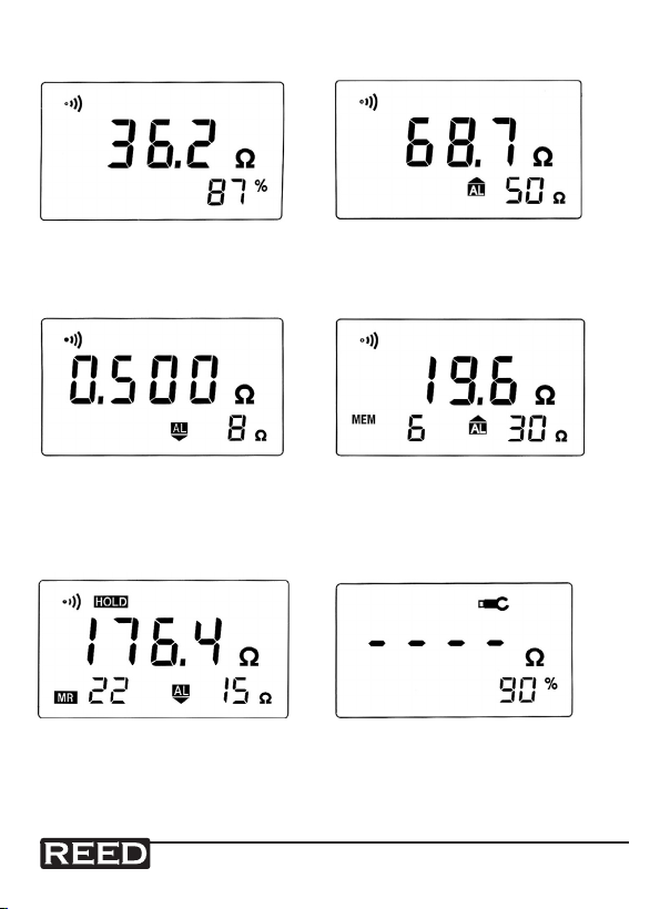
Schematics of Measurement
Buzzer ON.
A loop ground resistance
of 36.2Ω. The battery life
is at 87%.
Buzzer ON.
A loop ground resistance of 0.5Ω.
The ground resistance value is
below the low alarm threshold of 8Ω,
a beep will sound.
Buzzer ON.
Read the 22nd recorded
measurement, the ground resistance
is 176.4Ω. The ground resistance low
alarm threshold is set at 15Ω.
www
reedinstruments
www.GlobalTestSupply. com
Buzzer ON.
A loop ground resistance of 68.7Ω
The ground resistance value is
above the high alarm threshold of 50Ω,
a beep will sound.
Buzzer ON.
A loop ground resistance of 19.6Ω.
The ground resistance value is
below the high alarm threshold of 30Ω,
no beep will sound. There are 6 recorded
values in the memory.
The jaw is not closed properly.
The battery life is at 90%.
continued ...
com
11

Pantone 534 Blue
Pantone 123 Yellow
Pantone 485 Red
Pantone 123 Yellow
Pantone 534 Blue
Black
Rich Black -
20/20/20/100
Blue - 100/80/30/5
Yellow - 0/27/100/0
Red - 10/100/100/5
Yellow - 0/27/100/0
Blue - 100/80/30/5
Buzzer ON.
A loop ground resistance of 93.7Ω.
The battery life is at 18%.
At less than 20% the batteries need
to be replaced. Auto power off has
been enabled. There are 6 recorded
values in the memory.
Buzzer ON.
The current in the grounding loop has
been disturbed, the reading is 55.2Ω,
however the resistance measurement
could have been affected. The battery
life is at 86%.
Current Measurement
1. Press the arrow A button.
2. The display will show the current unit of measure, A or mA. You can
now measure the current of the conductor.
3. Read the measurement value on the display.
4. If the display shows the OL symbol, this indicates the measured
value exceeds the measurement range.
www
www.GlobalTestSupply. com
reedinstruments
com
continued ...
12

Pantone 534 Blue
Pantone 123 Yellow
Pantone 485 Red
Pantone 123 Yellow
Pantone 534 Blue
Black
Rich Black -
20/20/20/100
Blue - 100/80/30/5
Yellow - 0/27/100/0
Red - 10/100/100/5
Yellow - 0/27/100/0
Blue - 100/80/30/5
Alarm Operation
1. When in the resistance measurement mode, press the AL button,
the AL symbol and the value of the alarm threshold will be displayed.
2. You can press the AL button several times to select one of
three alarm modes:
Low Alarm Mode: When the measurement is below the alarm threshold,
a continuous beep will sound at low frequency. The AL symbol will show
on the display.
High Alarm Mode: When the measurement is above the alarm
threshold, a continuous beep will sound at high frequency. The
AL
symbol will show on the display.
No Alarm Mode: No measurement has been set in the alarm threshold.
3. Set the alarm threshold. The default setting is high alarm threshold of
20Ω. In the resistance measurement mode, press the POWER + AL
buttons to set the alarm threshold value. The AL symbol and the value
of the alarm threshold will be displayed. Press the A or Ω buttons
to increase or decrease the alarm threshold value, can range from 1 to
100Ω inclusively. You can now select one of the three alarm modes by
pressing the AL button several times. Once done, press the to exit
the alarm value setting mode. This value will not change when the meter
is turned off.
Memory
Clearing the memory
Press the HOLD + MEM buttons for 3 seconds, the CLR symbol will
then appear on the display. Once the beep sounds, the memory has
been cleared. The meter will return to the measurement
mode automatically.
Saving measured values
Press the MEM button for 2 seconds, the MEM symbol will then appear
on the display. The number of records will automatically increase by
one, which is then indicated on the display. When the record is the 99th
or when the battery life is at less than 20%, a beep will sound when the
MEM button is pressed to indicate that the meter will not record the value.
www
www.GlobalTestSupply. com
reedinstruments
com
continued ...
13

Pantone 534 Blue
Pantone 123 Yellow
Pantone 485 Red
Pantone 123 Yellow
Pantone 534 Blue
Black
Rich Black -
20/20/20/100
Blue - 100/80/30/5
Yellow - 0/27/100/0
Red - 10/100/100/5
Yellow - 0/27/100/0
Blue - 100/80/30/5
Reading the recorded measurements
Press the POWER + MEM buttons for 1 second, the MR and HOLD
symbols will then appear on the display. The number of the reading and
the value will be shown one at a time. To display the previous or following
record simply press the A or Ω buttons. Press the POWER button to
exit the read record mode and return to resistance measurement mode.
Special Functions
Turning the buzzer ON & OFF
Press the POWER + Ω buttons, the
the display and the buzzer is now off. When the buzzer is off, there will
be no beep sound when pressing the buttons and the alarm function is
disabled. Press the POWER + Ω buttons to turn the buzzer back on.
Turning the auto power off ON & OFF
Press the POWER + HOLD buttons, the P symbol will appear on the
display and the auto power off function will be enabled. After 5 minutes of
no operation, the meter will turn itself off automatically. Press the POWER
+ HOLD buttons again and the P symbol will disappear from the display.
The auto power off function is now disabled. Press the POWER button for
2 second to turn the meter off manually.
Overload Function
OL will appear on the screen when the measured value exceeds the
measurement range (1200Ω resistance and 20A current).
Hold
Press the HOLD button to record the current measurement
in measurement mode.
buzzer symbol will disappear from
www
www.GlobalTestSupply. com
reedinstruments
com
14

Pantone 534 Blue
Pantone 123 Yellow
Pantone 485 Red
Pantone 123 Yellow
Pantone 534 Blue
Black
Rich Black -
20/20/20/100
Blue - 100/80/30/5
Yellow - 0/27/100/0
Red - 10/100/100/5
Yellow - 0/27/100/0
Blue - 100/80/30/5
Battery Replacement
The symbol indicates that the batteries are weak
and they need to be replaced.
1. Turn the meter off
2. Remove the screw on the battery cover
3. Remove the cover and the battery box
4. Remove the battery from the battery box
5. Install new battery, respecting the correct polarity
6. Reinstall the battery box and the cover
7. Reinstall the screw on the battery cover
Note: Use of the instrument for the rst time requires
the batteries to be charged for 10 hours.
For service on this or any other REED product or for information on other
REED products, contact REED Instruments at info@reedinstruments.com
www
www.GlobalTestSupply. com
reedinstruments
com
15

Pantone 534 Blue
Pantone 123 Yellow
Pantone 485 Red
Pantone 123 Yellow
Pantone 534 Blue
Black
Rich Black -
20/20/20/100
Blue - 100/80/30/5
Yellow - 0/27/100/0
Red - 10/100/100/5
Yellow - 0/27/100/0
Blue - 100/80/30/5
Field Applications
This ground resistance clamp meter is designed to test the ground
resistance of any loop system. In addition to measuring the ground
resistance of electric power transportation conductors and
communication circuitry, this meter also measures the ground resistance
of electric equipment and lightning arresters. When the current in
the grounding loop has been disturbed, the resistance measurement
can be affected. The interference current can be tested by the ground
resistance clamp.
Principles of Measurement
Rx: Ground resistance value to be tested
R1//R2//…Rn: multiple parallel ground resistance
Rearth: normally 0Ω
Rguard wire: normally 0Ω
Rloop=Rx+Rearth+(R1//R2//…Rn)+Rguard wire
When R1//R2//…Rn<<Rx, then Rloop=Rx
www
www.GlobalTestSupply. com
reedinstruments
com
continued ...
16

Pantone 534 Blue
Pantone 123 Yellow
Pantone 485 Red
Pantone 123 Yellow
Pantone 534 Blue
Black
Rich Black -
20/20/20/100
Blue - 100/80/30/5
Yellow - 0/27/100/0
Red - 10/100/100/5
Yellow - 0/27/100/0
Blue - 100/80/30/5
Distribution of Electric Power
The distribution of electric power on the ground is transmitted by wire
shelf, every wire post has it’s own ground protection. Measurement mode
as follows:
Configuration of Telecommunications System
To protect telephone lines from being interfered, the telecom maintenance
department uses conduction wires to insulate the telephone lines. As the
following drawing indicates, you can use the ground resistance clamp
meter to simply test each ground point.
www
www.GlobalTestSupply. com
reedinstruments
com
continued ...
17

Pantone 534 Blue
Pantone 123 Yellow
Pantone 485 Red
Pantone 123 Yellow
Pantone 534 Blue
Black
Rich Black -
20/20/20/100
Blue - 100/80/30/5
Yellow - 0/27/100/0
Red - 10/100/100/5
Yellow - 0/27/100/0
Blue - 100/80/30/5
Faraday Cage Protection System
The principle of the Faraday Cage is that the conduction wire is
connected with the ambient ground of one instrument, a group of
equipment or one building. It can’t be interfered with externally.
Application of Gas Stations
Testing of ground resistance is necessary for gas stations to prevent
static electricity. Apply ground electrodes of oil trough to supplementary
electrodes to test ground resistance of the gas station. The test result is
the sum for the ground resistance of the gas station and the ground
resistance of the oil trough in series.
As indicated in the above measurement mode, it can be applied to the
measurement of the lightning rod and the oil trough.
www
www.GlobalTestSupply. com
reedinstruments
com
18

Pantone 534 Blue
Pantone 123 Yellow
Pantone 485 Red
Pantone 123 Yellow
Pantone 534 Blue
Black
Rich Black -
20/20/20/100
Blue - 100/80/30/5
Yellow - 0/27/100/0
Red - 10/100/100/5
Yellow - 0/27/100/0
Blue - 100/80/30/5
Notes _________________________________________
________________________________________________
________________________________________________
________________________________________________
________________________________________________
________________________________________________
________________________________________________
________________________________________________
________________________________________________
________________________________________________
________________________________________________
________________________________________________
________________________________________________
________________________________________________
________________________________________________
________________________________________________
________________________________________________
________________________________________________
www
www.GlobalTestSupply. com
reedinstruments
com
19

Pantone 534 Blue
Pantone 123 Yellow
Pantone 485 Red
Pantone 123 Yellow
Pantone 534 Blue
Black
Rich Black -
20/20/20/100
Blue - 100/80/30/5
Yellow - 0/27/100/0
Red - 10/100/100/5
Yellow - 0/27/100/0
Blue - 100/80/30/5
Notes _________________________________________
________________________________________________
________________________________________________
________________________________________________
________________________________________________
________________________________________________
________________________________________________
________________________________________________
________________________________________________
________________________________________________
________________________________________________
________________________________________________
________________________________________________
________________________________________________
________________________________________________
________________________________________________
________________________________________________
________________________________________________
www
www.GlobalTestSupply. com
reedinstruments
com
20
 Loading...