

Page 1
Drilling Machines Operator’s Manual
1110-59300
1
ADVERTENCIA:
Lea y comprenda perfectamente todas las instrucciones antes
de operar cualquier máquina para aterrajar o perforar de Reed.
El incumplimiento de cualquiera de las instrucciones que
aparecen en este documento puede resultar en graves lesiones
personales o daños materiales.
ÍNDICE:
1) Información básica sobre el producto
2) Instrucciones de operación
3) Instrucciones de mantenimiento
4) Ilustraciones de partes, lista de partes y accesorios necesarios
1017-XXXXX
MÁQUINA COMBINADA PARA PERFORAR Y ATERRAJAR - CDTM1100, CDTM2100
WARNING:
Read and fully understand all instructions before operating any
of Reed’s tapping or drilling machines. Failure to follow all in-
structions listed inside, may result in serious personnel injury
and / or property damage.
CONTENTS:
1) Basic Product Information
2) Operating Instructions
3) Maintenance Instructions
4) Parts Illustration, Parts List, and Necessary Accessories
COMBINATION TAPPING & DRILLING MACHINE - CDTM1100, CDTM2100
DRILLING MACHINE - DM1100, DM2100
Drilling Machine Instructions
Instrucciones para Máquinas Perforadoras
DM2100
REED MANUFACTURING COMPANY
1425 West 8th St. P.O. Box 1321, Erie, Pa 16512 USA Phone: 800-666-3691 or 814-452-3691 Fax: 800-456-1697 or 814-455-1697
www.reedmfg
co.com
MÁQUINAS PERFORADORAS - DM1100, DM2100
0119-59305
1
0119-59305
Page 2
Drilling Machines Operator’s Manual
,COMBINATION TAPPING & DRILLING MACHINE - CDTM1100 CDTM2100
DRILLING MACHINE - DM1100, DM2100
Basic Product Information:
The TM1100 tapping machine drills and taps pressurized water mains.
The tool additionally installs a 3/4" or 1" corporation stops. The tool
can drill and tap 4"-48" cast or ductile iron and C-900 PVC. The base
tool requires saddles for specific sizes and chain extensions above
16". The tool uses Reed DT series drill taps.
The DM1100 and DM2100 drilling machines drill through the wall of
pressurized pipe via the corporation stop and saddle. These tools use
Reed D series drills and hole saws. The CDTM1100 and CDTM2100
combination machines use common components to assemble either
the drilling machine or the tapping machine.
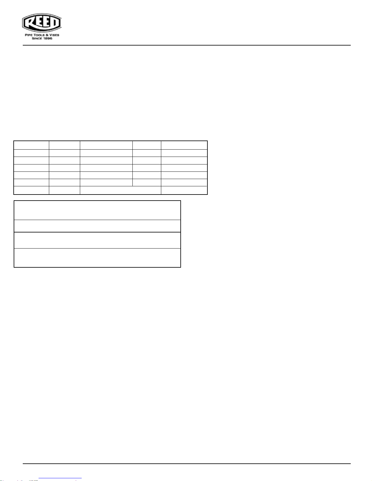
Catalog No. Item Code Size Pipe Dia.
CDTM1100 09304 3/4” - 1” TAP & DRILL 4”-48” TAP 114 lbs/52 kg
CDTM2100 09314 3/4” - 1” TAP/ 2” DRILL 4”-48” TAP 116 lbs/53 kg
DM1100 09302 3/4” - 1” N/A 58.2 lbs/26.5
DM2100 09312 3/4” - 2” N/A 60.9 lbs/27.7
DMBASE 09301 N/A N/A 35 lbs/15.9 kg
DM11BBEXT 99390 2” Iron Body Gate Valves
Additional Specifications
Tool Box overall outside dimensions:
Machine Clearance radius:
Pressure Rating
= 250 psi.
Operating Pressure Rating - 90 psi - ie - Drilling or Tapping into
pressurized mains.
Warning:
Drilling or Tapping into highly pressurized mains is not recommended.
However, it is permissible at pressure up
precautions and incorporating high pressure attachments such as the
Mueller® Power Clevis #H-10800. (See operations and maintenance
manual.) DO NOT USE on natural gas or petroleum piping.
• Flushing/blow by port: 1/2-14 NPT plugged port is provided in
bottom chamber for flushing chips while tapping into pressurized
mains.
• Swing check valve resists clogging and is easy to clean out.
• Manual pressure balancing and top chamber pressure relief valves
are accessible and easy to use.
• Manual or power drive operation through 13/16" square shaft
(Adapter sold separately).
Materials and Finish:
A. Hard anodized and powder epoxy painted aluminum frames.
B. Alloy steel boring bar.
C. Heavy duty steel chain and forged steel chain hooks.
D. Bronze and zinc aluminum parts.
E. EPR rubber gaskets and “O” rings.
F.
DM1100 = 26"
: Design pressure rating for valve and chamber
Plated steel parts.
Net Shipping
DM1100 23” x 10 1/2“ x 11 3/8”
to 250 psi, if utilizing special
8.2 lbs/3.7 kg
DM1100 / DM2100
Operating Instructions:
1. Select proper tools necessary to perform drilling operation.
A. Service saddle
B. Corporation stop
C. Drill size and drill adapter to match corporation stop bore
D. Corp adapter with flush valve
E.
Install sleeve #99301 for 1 ½” and 2” drilling/taps.(Figures 2 & 3).
a. Retract set screw in bearing assembly, slide
3. Insert corporation stop into saddle threads.
4. Screw the proper size black corporation adapter into the
brass threaded body of the machine.
5.
Assemble drill adapter and appropriate drill into boring bar.
adapter and hole saws with pilot drills are needed. Screw the hole saw
onto the arbor body and line up holes after hand tightening. Assemble
the driver into the body and hole saw. Insert the pilot drill into the arbor
body. Allow a maximum of 1/4” of the drill tip to protrude from the hole
saw. Line up the slot in the drill with the set screw and tighten with the
hex key wrench provided. (When using on PVC, a pilot drill is not necessary.) See Figure 1.
6. Screw corp adapter onto corporation stop.
7. Drilling
NOTES: • Always use tapping compound for cutters for ductile iron.
• Use tapping compound on the OD (outside diameter) of shell cutters
for PVC. Keep the ID clean so it can grab the coupon/plug and pull it
out of the pipe.
B.
C. Attach rat
NOTE: Do not overfeed the drills, hole saws or shell cutters, let the bits
do the cutting before feeding. Turn the drill, hole saw or shell cutter
one full revolution by hand before feeding. Do not force the drill.
D. Open the ball valve on the side of the corp adapter to allow the
E. Once the drill is completely through the pipe, release the yoke
off bearing assembly.
b. Slide sleeve in place; hole must line up.
c. Install bearing assembly.
NOTE: Do not use sleeve for ¾” and 1” drilling/ taps.
F. Gather any other necessary accessories to meet
operating requirements.
2. Assemble saddle to the pipe.
A. Clean area of pipe where tap is to be performed. REED DS12
(#08000)
B. Assemble service saddle on the pipe where desired
tighten securely.
A. Thread sealant may be used.
B. Tighten the corporation stops with a smooth jaw wrench;
DO NOT USE A PIPE WRENCH.
Note: Make sure corporation stop valve is open.
A. If you are using the unit for drilling 1 ½” or 2”, the hole saw
A. Run drill bit down until it touches the pipe.
Swing the star feed yoke over the top of the bearing and tighten star feed.
chet wrench on square drive and turn drill clock wise
while turning the feed housing to feed the drill.
flushing of chips.
star feed to allow the boring bar to return to its uppermost position.
or DS36 (#08006) descaler may be used.
and
2
0119-59305
Page 3
Drilling Machines Operator’s Manual
NOTE: Put downward pressure on the boring bar to keep it from traveling too fast upward and potentially damaging the machine.
8. Close off the corporation stop using an adjustable wrench.
9. Disassemble machine from corporation stop.
10. Assemble tubing to corporation stop per tubing and fitting
manufacturer’s specs.
CDTM1100 and CDTM2100
Operating Instructions:
1. Drilling
A. Convert direct tapping set up to drilling set up.
i. Remove 99307 Bearing Assembly by backing out the single
set screw.
ii. Remove the tapping boring bar from the 99300 Threaded Body
iii. Insert the drilling machine boring bar into the threaded body.
1. 3/4" and 1" branch taps - reinstall bearing assembly. Line the
set screw up with the lower hole in the boring bar. Drive the
screw in until recessing the screw slightly. (See figures 2 & 3)
2. 1-1/2" and 2" branch taps -
a. Install 99301 Sleeve.
b. Reinstall bearing assembly. Line the set screw up
with the lower hole in the boring bar. Drive the screw
in until recessing the screw slightly. (See figures 2 & 3)
c. Follow DM1100/DM2100 Operator's Manual #59305 to
drill for service lines.
2. Tapping
A. Convert drilling set up to tapping set up.
i. Remove 99307 Bearing Assembly.
screw out past the sleeve then remove the bearing
assembly and sleeve.
ii. Remove the drilling boring bar from the 99300 Threaded Body
iii.Insert the tapping machine boring bar into the threaded body.
iv. Reinstall the bearing assembly on the taping bar.
v. Line the set screw up with the lower hole in the boring bar.
Drive the screw in until recessing the screw slightly.
B.
Follow TM1100 Operator's Manual #95300 to direct tap service
lines.
Back the single set
Maintenance Instructions:
CDTM1100, CDTM2100, DM1100, DM2100
Before Using
1. Clean and oil all bearing and wear surfaces and threads.
2. Inspect and clean tapping bits, and remove chips and scale.
Chips and scale may prevent proper function of the tool.
3. Inspect and clean the Boring Bar tool end. Chips and scale may
interfere with the insertion of the tapping bit or adapter shank.
After Using
1. Clean the machine and oil the machined surfaces. If necessary,
the top and bottom chambers can be easily disassembled to
clean more thoroughly.
2. Lubricate the tool holding area of the boring bar with REED
#98425 Tapping Compound.
3. If necessary, flush the bottom chamber with a water hose to
remove any chips. DO NOT hammer frames to remove chips or
debris - Handle Carefully!
4. Protect threaded pieces by assembling them with their mating
parts.
5. Periodically, inspect the Boring Bar’s o-ring seals and replace
if worn.
6. Carefully, place the tool back in the toolbox for storage.
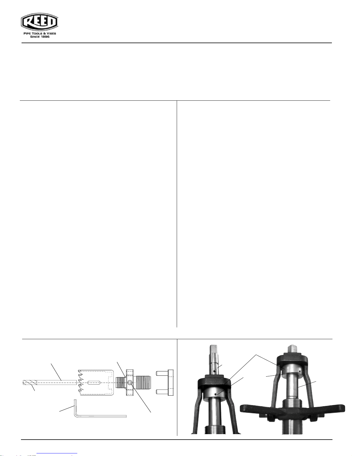
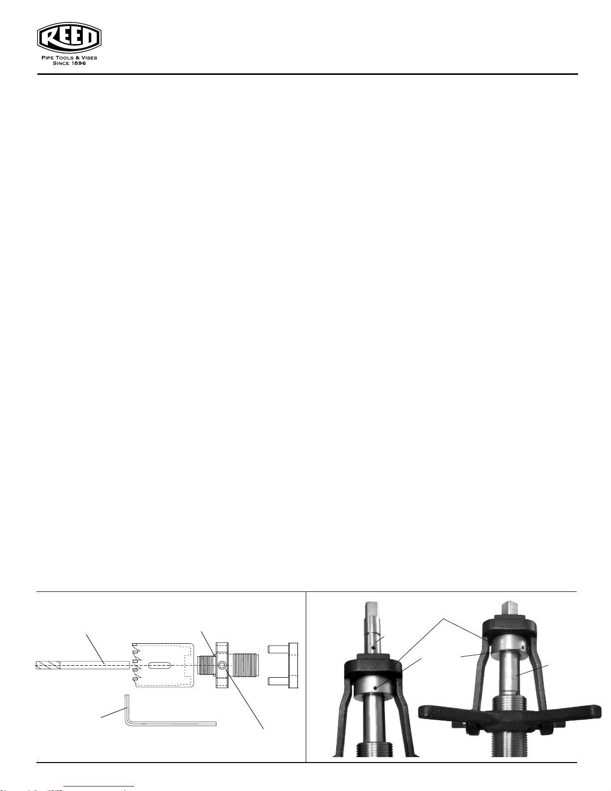
Figure 1
Line up notch with set screw—to
prevent pilot drill from
when drilling.
1/4” Pilot Drill
1/8” Hex wrench for
tighting set screw on
Arbor body
Note: Do not use pilot when drilling PVC pipe.
0119-59305
twisting
Hole Saw spacer 113 “O” ring
.56” ID .75 OD x 3/321 installed
between saw and arbor
Hole Saw
Body
1/4” set screw for
attaching pilot drill
Figure 2
Ready to drill
1” or 3/4”
DriverArbor
Bearing Assembly
Sleeve
Removed
Set Screw
Figure 3
Sleeve
Installed
3
Page 4
Drilling Machines Operator’s Manual
MÁQUINA PARA PERFORAR - DM1100, DM2100
MÁQUINA COMBINADA PARA PERFORAR Y ATERRAJAR - CDTM1100, CDTM2100
rodarepo led launaM rarofrep arap saniuqáM
Información básica sobre el producto:
La máquina para aterrajar TM1100 perfora y aterraja conducciones de
agua a presión. Además, la herramienta instala una pieza de
incorporación de 3/4 ó 1 pulg. La herramienta puede perforar y aterrajar
hierro fundido o dúctil de 4-48 pulg. y C-900 PVC. La herramienta básica
requiere carros portaherramientas para tamaños específicos y
extensiones de cadena para más de 16 pulg. La herramienta usa machos
de terraja de perforación Reed de la serie DT.
Las máquinas de perforación DM1100 y DM2100 perforan la pared de
tuberías a presión mediante la pieza de incorporación y el carro
portaherramientas. Estas herramientas usan brocas y sierras de perforar
Reed de la serie D. Las máquinas combinadas CDTM1100 y CDTM2100
usan componentes comunes para ensamblar la máquina para perforar o
la máquina para aterrajar.
obut ed .máiDoñamaTotnemele ed ogidóCogolátac ed ºN
Peso neto de transp.
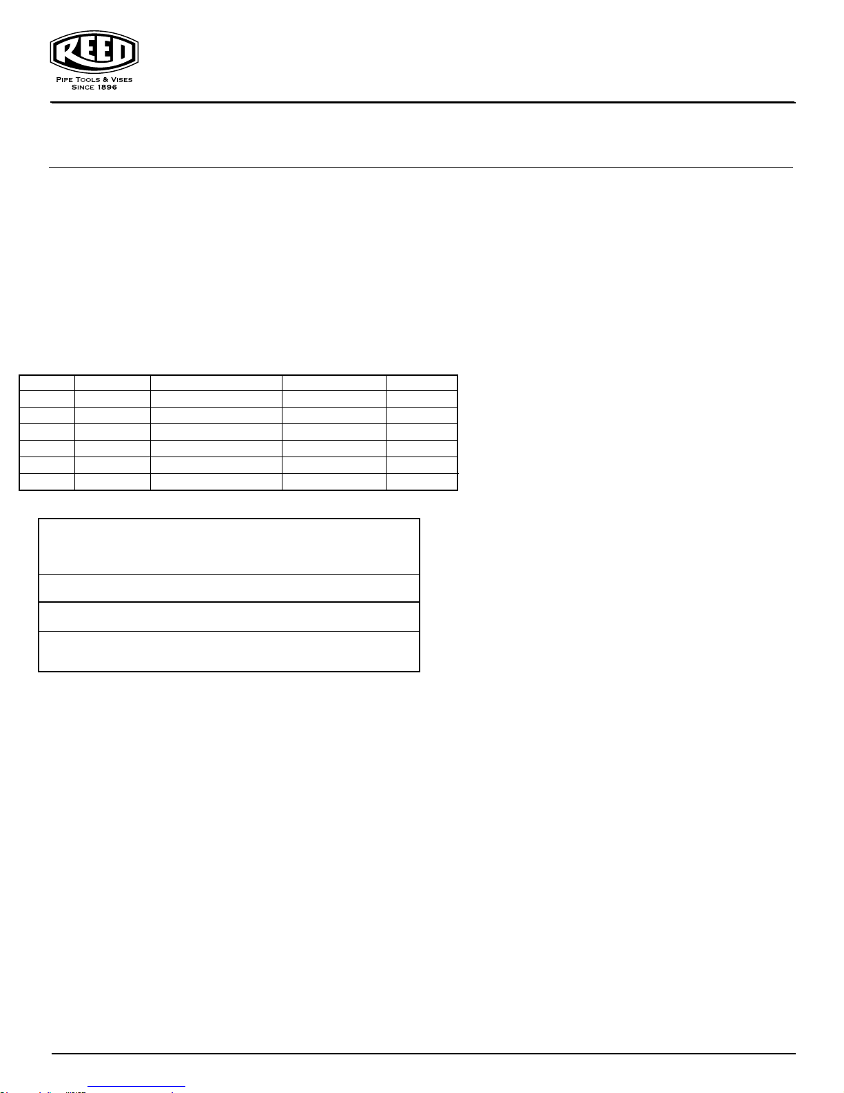
CDTM1100 09304 TERRAJA Y BROCA 3/4 - 1 pulg. MACHO TERRAJA 4-48 pulg. 114 lb./52 kg
CDTM2100 09314 TERRAJA 3/4 - 1 pulg./BROCA 2 pulg. MACHO TERRAJA 4-48 pulg. 116 lb./53 kg
DM11BBEXT 99390 2” Iron Body Gate Valves 8.2 lb/3,7 kg
Especificaciones adicionales
• Dimensiones exteriores generales de la caja de herramient
• Radio de separación de la máquina:
• Presión nominal: Presión nominal de diseño para válvula y cámara = 250 psi.
• Presión nominal operativa: 90 psi; es decir, aterrajar o perforar en conductos a
DM1100 23 x 10 1/2 x 11 3/8 pulg.
presión.
Advertencia:
No se recomienda taladrar ni aterrajar en conducciones con muy alta
presión. Sin embargo, se permiten a presiones de hasta 250 psi si se
utilizan precauciones especiales y se incorporan accesorios para alta
presión, como la horquilla eléctrica Mueller® #H-10800
manual de operación y mantenimiento). NO UTILICE en tuberías de gas
natural o petróleo.
• Limpieza/soplado por orificio: En la cámara inferior se incluye un orificio
con tapón de 1/2-14 NPT para el vaciado de las
en conducciones a presión.
• La válvula de charnela de verificación resiste los atascos y es fácil de
limpiar.
• La válvula de equilibrado de presión manual y la válvula de seguridad de
presión de la cámara superior son accesibles y fáciles de usar.
• Operación manual o eléctrica mediante eje cuadrado de 13/16 pulg. (el
adaptador se vende por separado).
Materiales y acabado:
A. Bastidores de aluminio duro anodizado y pintados con epoxy
pulverizado.
B. Barra taladradora de aleación de acero.
C. Cadena de acero de alta resistencia y ganchos de cadena de acero
forjado.
D. Partes de aluminio
E. Juntas y juntas tóricas de goma EPR.
F. Partes chapadas en acero.
de bronce y zinc.
as:
DM1100 = 26 pulg.
. (Consulte el
virutas mientras se aterraja
DM1100 / DM2100
Instrucciones de operación:
1. Seleccione las herramientas adecuadas necesarias para realizar
la operación de perforación.
A. Carro portaherramientas de servicio
B. Pieza de incorporación
C. El tamaño de la broca y el adaptador de la broca deben
corresponder con el orificio de la pieza de incorporación
D. Adaptador de incorporación con válvula de vaciado
E. Para 1 1/2 y 2 pulg. instale el manguito 99301. (Consulte las figuras
2 y 3).
a. Haga retroceder el tornillo de fijación en el conjunto de
cojinetes, deslice hacia afuera dicho conjunto.
b. Deslice el cojinete en su lugar (el orificio debe estar alineado).
c. Instale el conjunto de cojinetes.
F. Cualquier otro accesorio necesario para satisfacer las
necesidades operativas.
2. Ensamble el carro por
A. Limpie el
gk 5,62/.bl 2,85A/N”1 - ”4/3203900011MD
gk 7,72/.bl 9,06A/N”2 - ”4/3213900012MD
gk 9,51/.bl 53A/NA/N10390ESABMD
7. Perforación
A. Lleve la broca hacia abajo hasta que toque la tubería.
B. Gire la empuñadura de la leva y apriete.
C. Acople la llave de trinquete sobre un accionamiento cuadrado y gire
NOTA: No
D. Abra la válvula esférica en el lado del adaptador de incorporación
E. Cuando la broca haya atravesado completamente la tubería, suelte
NOTA: Ejerza presión hacia abajo en la barra taladradora para evitar que
se desplace demasiado rápido hacia arriba y pueda dañar la máquina.
8. Cierre la pieza de incorporación utilizando una llave ajustable.
9. Desmonte la máquina de la pieza de incorporación.
10. Acople la tubería a la pieza
REED DS12 (#08000) o DS36 (#08006).
B. Monte el carro portaherramientas de servicio en la tubería, donde
lo desee, y apriete con seguridad.
3. Inserte la pieza de incorporación en las roscas del carro
portaherramientas.
A. Puede usarse sellante para roscas.
B. Apriete la pieza de incorporación con una llave ajustable.
Nota: asegúrese de que la válvula de la pieza de incorporación está
abierta.
4. Atornille el cuerpo roscado en el adaptador de incorporación.
5. Monte el adaptador de perforación y la broca apropiada en la
barra taladradora.
A. Si utiliza la unidad para perforar 11/2 ó 2 pulg., se necesitan el
adaptador para sierras de perforar y sierras de perforar con brocas piloto.
Atornille la sierra de perforar en el cuerpo del portabro
tras apretar a mano. Monte el conductor en el cuerpo y la sierra de perforar.
Inserte la broca piloto en el cuerpo del portabrocas. Deje que sobresalga
un máximo de 1/4 pulg. de la punta de la broca desde la sierra de perforar.
Alinee la ranura en la broca con el tornillo de fijación y apriete con la llave
hexagonal provista. (Si usa en PVC no se necesita broca piloto). Consulte
la figura 1 más adelante.
6. Atornille el adaptador de incorporación en la pieza de
incorporación.
la broca en el sentido de las agujas del reloj mientras gira el
alojamiento de avance para hacer avanzar la broca.
para permitir que salgan las virutas.
la empuñadura de la leva para permitir que la barra taladradora
regrese a su posición más alta.
especificaciones del fabricante de las tuberías y los accesorios.
área de la tubería donde va a aterrajar Pueden usarse
intente hacer avanzar demasiado ni forzar la broca.
taherramientas a la tubería.
cas y alinee los orificios
de incorporación según las
4
0119-59305
Page 5
Drilling Machines Operator’s Manual
CDTM1100 y CDTM2100
Instrucciones de operación:
1. Perforación
A. Convierta la configuración directa para aterrajar en configuración para
perforar.
i. Retire el conjunto de cojinetes 99307 extrayendo el único tornillo
de fijación.
ii. Retire la barra taladradora para aterrajar del cuerpo roscado
99300.
iii. Inserte la barra taladradora de la máquina para perforar en el
cuerpo roscado.
1. Machos de
el conjunto de cojinetes. Alinee el tornillo de fijación con el orificio
inferior en la barra taladradora. Introduzca el tornillo hasta que
sobresalga ligeramente.. (Consulte las figuras 2 y 3).
B. Machos de terraja de derivación de 1-1/2 y 2 pulg.:
Instale el manguito 99301.
i.
Vuelva a instalar el conjunto de cojinetes. Alinee el tornillo de
ii.
fijación con el orificio inferior en la barra taladradora. Introduzca el
tornillo hasta que sobresalga ligeramente.(Consulte las figuras 2 y 3).
iii.
Siga el manual del operador DM1100/DM2100 N.º 59305 para perforar
líneas de servicio.
2. Aterrajar
A. Convierta la configuración para perforar en configuración
para aterrajar.
i. Retire el conjunto
fijación que hay más allá
ii. Retire la barra taladradora para perforar del
cuerpo roscado 99300.
Inserte la barra taladradora de la máquina para
iii.
aterrajar en el cuerpo roscado.
iv. Vuelva a instalar el conjunto de cojinetes en la barra para
aterrajar.
v. Alinee el tornillo de fijación con el orificio inferior en la barra
taladradora. Introduzca el tornillo hasta que sobresalga
ligeramente.
B.
Siga el Manual del operador TM1100 N.º 95300 para aterrajar
líneas de servicio.
terraja de derivación de 3/4 y 1 pulg.: vuelva a instalar
de cojinetes 99307. Retire
el único tornillo de
del manguito y luego retire el conjunto
de cojinetes y el manguito.
Instrucciones de mantenimiento:
CDTM1100, CDTM2100DM1100, DM2100,
Antes de usar
1. Limpie y engrase todas las roscas y superficies de cojinetes y de
desgaste.
2. Inspeccione y limpie las brocas de aterrajar y retire las virutas y las
rebabas. Las virutas y las rebabas pueden evitar que la herramienta
funcione adecuadamente.
3. Inspeccione y limpie el extremo de la herramienta de la barra
taladradora. Las virutas y las rebabas pueden interferir con la
inserción de la broca para aterrajar o la espiga del adaptador.
Después de usar
1. Limpie la máquina y engrase las superficies maquinadas. Si es
necesario, resulta muy fácil desmontar las cámaras superior e
inferior para limpiar más a fondo.
2. Lubrique el área de soporte de la barra taladradora con compuesto
para aterrajar REED #98425.
3. Si es necesario, limpie la cámara inferior con una manguera de agua
para eliminar cualquier viruta. NO golpee con un
bastidores para eliminar las virutas
o los residuos: ¡trate con
cuidado!
4. Proteja las piezas roscadas montándolas con sus partes
correspondientes.
5. Periódicamente, inspeccione los sellos de la junta tórica de la barra
taladro y reemplace si están desgastados.
6. Con cuidado, coloque la barra de nuevo en la caja de herramientas
para su almacenamiento.
martillo los
rodarepo led launaM rarofrep arap saniuqáM
Figura 1
Alinee la muesca con el tornillo de
fijación: para evitar que la broca
piloto se retuerza al perforar.
Broca piloto 1/4 pulg.
Llave hexagonal de 1/8
pulg. para apretar el
tornillo de fijación en el
cuerpo del portabrocas.
Separador de sierra de perforar 113 Junta
tórica diámetro int. 0,56 pulg. x diámetro
ext. 0,75 x 3/321 instalada entre sierra y
portabrocas.
Sierra de
perforar
Cuerpo del
portabrocas
Tornillo de fijación de 1/4 pulg.
para acoplar la broca piloto
Nota: no utilice broca piloto al perforar tubos de PVC.
0119-59305
Conductor
de arrastre
Figura 2
Listo para
perforar
1 ó 3/4 pulg.
Conjunto de cojinetes.
Manguito
retirado
Tornillo de
fijación
Figura 3
Listo para
perforar
1
/2 ó 2
1
pulg.
Mangu ito
instalado
5
Page 6
Drilling Machines Operator’s Manual
T launaM s’rotarepO senihcaM gnillirD & gnippa
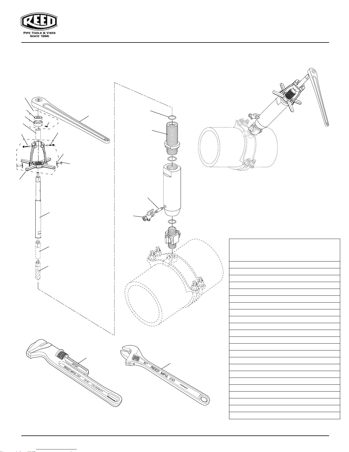
DM1100/DM2100 Replacement Parts
DM1100/DM2100 Partes
7
10
8
4
21
20
11
1
22
23
12
2
9
3
6
5
17
18
Drilling Parts List
Lista de partes para
perforación
Ref. No. Description REED Item Code
Nº de ref. Descripción Código de ítem
REED
1 Boring Bar 99304
2 O-Ring 40377
3 Threaded Body 99300
4 Star Feed & Yoke 99305
5 Hex Head Cap Screw (2) 30118
6 Washer (2) 39305
7 Bearing Assembly 99307
8 Spring (2) 94304
9 Set Screw (2) 38495
10 Sleeve 99301
11 Set Screw 39306
12 Ratchet Handle 40383
13 Carrying Case 40429
16
19
14 Operating Manual 59300
15 Tapping Compound 98425
16 RSPUD Wrench 02112
17 Brass Nipple 97564
18 Ball Valve 40396
19 CW10 Wrench 02205
20 Bearing 40414
21 Bearing Retainer 99306
22 Drill Adapter see next page
23 Drill / Hole Saw see next page
6
0119-59305
Page 7
Options
For #22
Options
For #23
Drilling Machines Operator’s Manual
Choose
the size
that ts
the job!
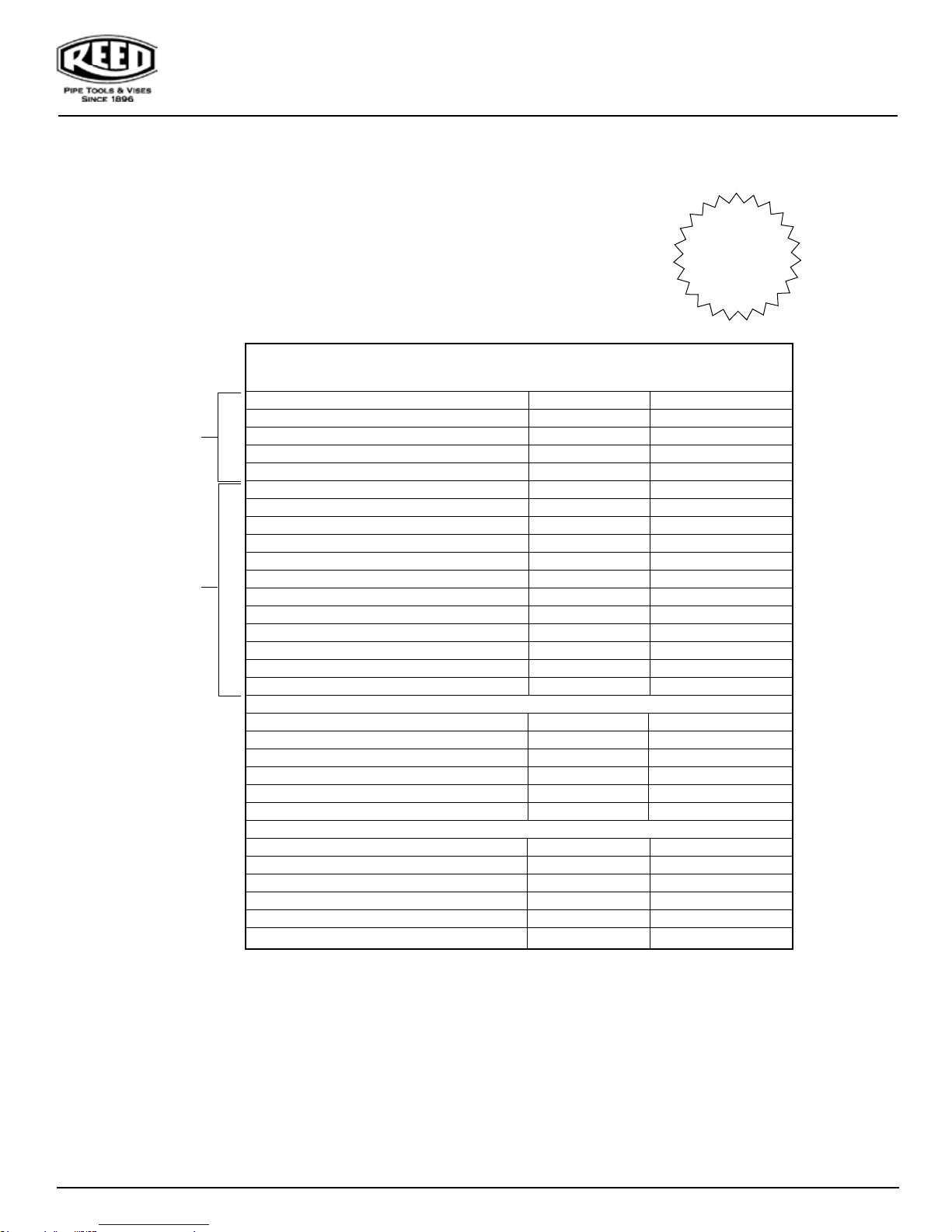
DM1100/DM2100/DMBASE Necessary Accessories
DM1100/DM2100/DMBASE Accesorios necesarios
DESCRIPTION CATALOG NO. ITEM CODE
DESCRIPCIÓN N DE CATÁLOGO CÓDIGO DE ITEM
Drill Adapters
** Drill Adapter 3/4" DMDA75 98461
** Drill Adapter 1" DMDA100 98462
*** Hole Saw Adapter DMHSA 08413
Drill Adapter - PVC DMAPVC 94150
Drills/Hole Saws
11/16" Drill D688 04380
7/8" Drill D875 04381
15/16" Drill D938 04382
1-7/16” Hole Saw HS1438 04370
1-3/4” Hole Saw HS1750 04371
1-7/8” Hole Saw HS1875 04372
1/4” Pilot Drill HSPD 04561
11/16” Shell Cutter PL688 04385
7/8” Shell Cutter PL875 04386
1-7/16” Shell Cutter PL1438 04387
1-3/4” Shell Cutter PL1750 04392
Corp Stop Adapters
** 3/4” AWWA Corp Adapter DMCA75 08423
** 1” AWWA Corp Adapter DMCA100 08424
*** 1-1/2”AWWA Corp Adapter DMCA150 08425
*** 2” AWWA Corp Adapter DMCA200 08426
1-1/2” NPT Corp Adapter DMCA150NPT 08428
2” NPT Corp Adapter DMCA200NPT 08429
Miscellaneous
3/4” NPT to AWWA Converter DM75CONV 98472
1” NPT to AWWA Converter DM100CONV 98473
Power Drive Adapter TMPDA 08430
Magnetic Coupon Retainer Set, 3/8" MCR3/8 08358
Magnetic Coupon Retainer Set, 1/4" MCR1/4 08359
** Coupon Retaining Drill Bit CRPD25 99129
** Standard with DM1100 & DM2100 machines
*** Standard with DM2100 machines
0119-59305
See Also RP-91
7
Page 8
Drilling Machines Operator’s Manual
Reed Lifetime Warranty
Reed Hand Tools are for the professional trade and are warranted against all failure due to defects in workmanship and materi-
als for the normal life of the tool.
FAILURES DUE TO MISUSE, ABUSE, OR NORMAL WEAR AND TEAR ARE NOT COVERED BY THIS WARRANTY.
NO PARTY IS AUTHORIZED TO EXTEND ANY OTHER WARRANTY. NO WARRANTY FOR MERCHANTABILITY OR FIT-
NESS FOR A PARTICULAR PURPOSE SHALL APPLY.
No warranty claims will be allowed unless the product in question is received freight prepaid at the Reed factory. All warranty
claims are limited to repair or replacement, at the option of the company, at no charge to the customer. REED IS NOT LIABLE
FOR ANY DAMAGE OF ANY SORT, INCLUDING INCIDENTAL AND CONSEQUENTIAL DAMAGES. Some states do not allow the
exclusion or limitation of incidental or consequential damages, so the above exclusion may not apply.
This warranty gives you specific legal rights, and you may also have other rights which vary from state to state.
Garantía de por vida de Reed
Las herramientas manuales de Reed son para el negocio profesional y están garantizadas contra cualquiera avería por defectos
en manos de obra y de materiales durante la vida normal de dichas herramientas.
LAS AVERÍAS DEBIDO AL MAL USO Y EL ABUSO, O LA ROTURA Y EL DESGASTE NORMALES, NO ESTÁN CUBIERTAS
POR ESTA GARANTÍA.
NADIE ESTÁ AUTORIZADO PARA OTORGAR NINGUNA OTRA GARANTÍA. NO SE APLICARÁ NINGUNA GARANTÍA DE
COMERCIABILIDAD O IDONEIDAD PARA UN FIN PARTICULAR.
No se permitirá ningún reclamo de garantía excepto que el producto en cuestión se reciba con fletes prepagados en la fábrica
de Reed. Todos los reclamos de garantía están limitados a reparación o sustitución, a elección de la compañía, y sin cargo para el
cliente. REED NO ES RESPONSABLE DE DAÑOS DE NINGÚN TIPO, INCLUIDOS LOS CIRCUNSTANCIALES E INDIRECTOS.
En algunos estados no se permite la exclusión o la limitación de los daños circunstanciales o indirectos, por lo que la exclusión
anterior puede no aplicar.
Esta garantía le otorga derechos legales específicos, y usted puede contar también con otros derechos que varían de
estado a estado.
Power units for Universal Pipe Cutters, Saw It® pneumatic saw, hydrostatic test pumps, cordless power pipe bevelers, and
threading power drives are warranted for a period of one year from date of purchase. Hydraulic pumps for PE Squeeze-Off tools
have a one year warranty from date of purchase.
Las unidades motrices para cortatubos universales UPC, sierra neumática Saw It®, bombas para pruebas hidrostáticas,
biseladoras inalámbricas, motopropulsores para roscadora y las bombas hidráulicas para prensas de flujo PE tienen una garantía
de un año a partir de la fecha de compra.
REED will repair or replace tools with any defects due to faulty materials or workmanship for one (1) year or ve (5) years from the date of purchase, as
applicable. This warranty does not cover part failure due to tool abuse, misuse, or damage caused where repairs or modications have been made or
attempted by non REED authorized repair technicians. This warranty applies only to REED tools and does not apply to accessories. This warranty applies
exclusively to the original purchaser.
One (1) year warranty: Power units for pneumatic, electric, hydraulic and battery-powered tools have a one year warranty. This includes, but is not
limited to REED pumps, universal pipe cutter motors, power drives, power bevel tools, threading machines, cordless batteries and chargers.
Five (5) year warranty: Any REED tool not specied under the one (1) year warranty above is warrantied under the REED ve (5) year warranty.
NO PARTY IS AUTHORIZED TO EXTEND ANY OTHER WARRANTY. NO WARRANTY FOR MERCHANTABILITY OR FITNESS FOR A PARTICULAR PURPOSE SHALL APPLY.
No warranty claims will be allowed unless the product in question is received freight prepaid at the REED factory. All warranty claims are limited to repair
or replacement, at the option of REED, at no charge to the customer. REED is not liable for any damage of any sort, including incidental and consequential
damages. This warranty gives you specic legal rights, and you may also have other rights which vary by state, province or country.
REED Limited Warranty
Warranty Eective December 1, 2018
REED reparará o reemplazará las herramientas con cualquier defecto debido a defecto en materiales o mano de obra durante un (1) año o cinco (5) años
a partir de la fecha de compra, según corresponda. Esta garantía no cubre las fallas de las piezas debido al abuso, mal uso o daños causados por reparaciones o modicaciones realizadas o intentadas por técnicos de reparación no autorizados por REED. Esta garantía se aplica solo a las herramientas
REED y no se aplica a los accesorios. Esta garantía se aplica exclusivamente al comprador original.
Un (1) año de garantía: Las unidades de potencia para herramientas neumáticas, eléctricas, hidráulicas y alimentadas por baterías tienen una garantía
de un año. Incluye, entre otras cosas, bombas REED, motores universales para cortatubos, motopropulsores, herramientas de biselado, máquinas
roscadoras, baterías inalámbricas y cargadores.
Cinco (5) años de garantía: Cualquier herramienta REED que no esté especicada bajo la garantía de un (1) año ya mencionada cuenta con la garantía
de cinco (5) años de REED.
NINGUNA DE LAS PARTES ESTÁ AUTORIZADA A EXTENDER NINGUNA OTRA GARANTÍA. NO SE APLICARÁ NINGUNA GARANTÍA DE COMERCIABILIDAD O IDONEIDAD PARA UN PROPÓSITO PARTICULAR.
No se permitirán reclamos de garantía a menos que el producto en cuestión se reciba en la fábrica de REED con el ete pagado por adelantado. Todos
los reclamos de garantía se limitan a la reparación o reemplazo, a elección de REED, sin costo alguno para el cliente. REED no es responsable de ningún
daño de ningún tipo, incluyendo daños incidentales y emergentes. Esta garantía le otorga derechos legales especícos y también puede tener otros
derechos que varían según el estado, la provincia o el país.
Garantía efectiva a partir del 1 de diciembre de 2018
Garantía Limitada REED
Reed Manufacturing Company
1425 West 8th Street • Erie, PA 16502 • USA
Telephone: 814-452-3691 Fax: 814-455-1697
www.reedmfgco.com
8
http://videos.reedmfgco.com/drillingmachines
0119-59305
 Loading...