

Page 1
Approved to
the latest United
States and CSA
Canadian
standards
launaM s’rotarepO evirD rewoP DP1035
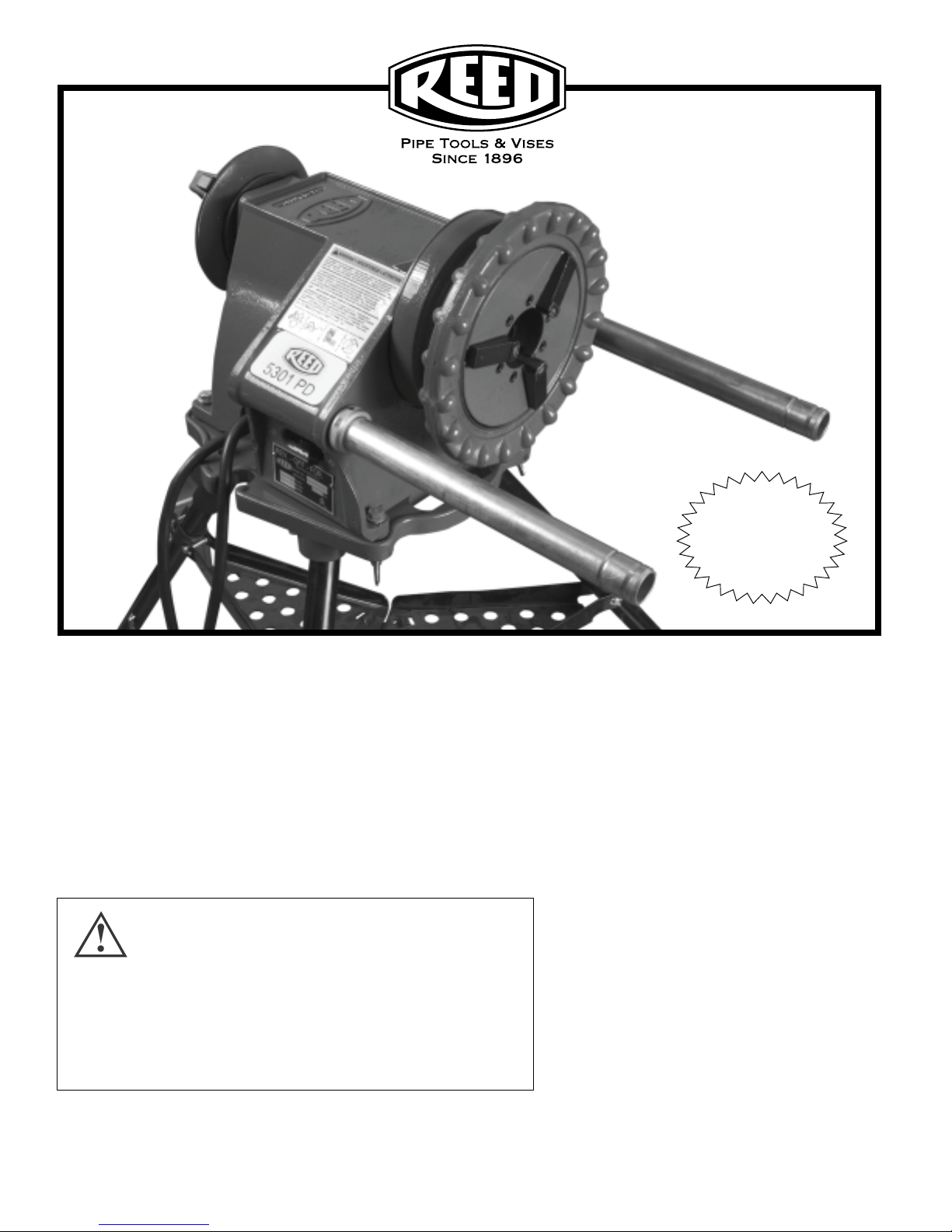
5301PD Power Drive
OPERATOR’S MANUAL
The electric-motor-driven REED 5301PD Power Drive centers and
chucks pipe and conduit and rotates it while cutting, threading, and
reaming operations are performed. FORWARD (clockwise) rotation
can be selected with the REV/OFF/FOR switch.
WARNING!
READ AND UNDERSTAND ALL INSTRUCTIONS.
FAILURE TO FOLLOW ALL INSTRUCTIONS LISTED
INSIDE MAY RESULT IN ELECTRIC SHOCK, FIRE,
AND/OR SERIOUS PERSONAL INJURY.
1425 West 8th St. P.O. Box 1321, Erie, Pa 16512 USA Phone: 800-666-3691 or 814-452-3691 Fax: 800-456-1697 or 814-455-1697
910-55301
• Includes Footswitch.
• Footswitch cord is 5’ 6” (1676 mm) long.
REED MANUFACTURING COMPANY
www.reedmfgco.com
SAVE THESE
INSTRUCTIONS!
1
0416-55301
Page 2

TABLE OF CONTENTS
General Safety Information.......................................................................................3
Work Area Safety .....................................................................................................3
Electrical Safety ......................................................................................................3
Personal Safety .......................................................................................................3
Tool Use and Care ....................................................................................................4
Service ................................................................................................................4
Specific Safety Information ...........................................................................................4
Foot Switch Safety ..................................................................................................4
Threading Machine Safety .......................................................................................5
Machine Maintenance ................................................................................................5
Description, Specifications and Accessories ..............................................................5
Description ....................................................................................................5
Specifications ...................................................................................................5
Accessories ...................................................................................................5
launaM s’rotarepO evirD rewoP DP1035
Operation Using Hand Tools ...........................................................................................6
Installing Pipe in Power Drive ...................................................................................6
Cutting Pipe with Hand Cutter ..................................................................................6
Reaming Pipe with Hand Reamer ............................................................................6
Threading Pipe with Hand Threader ...........................................................................6
Operation Using Power Drive Mounted Tools .............................................................7
Installing 05307 Carriage, Die Head, 05308 Reamer, and 05309 Cutter .....................7
Cutting Pipe with 05309 Cutter ................................................................................7
Reaming Pipe with 05308 Reamer ...........................................................................8
Threading Pipe with R811 Die Head .............................................................8
Installing Dies in R811 Die Head ...........................................................................8
Maintenance Instructions............................................................................................9
Jaw Insert Replacement ...............................................................................................9
Lubrication ..............................................................................................................9
Motor Brush Replacement ...........................................................................................9
Motor Replacement ...................................................................................................9
Parts Diagrams..........................................................................................................10
Wiring Diagram and Wiring Schematics ................................................................16
Lifetime Warranty ..........................................................................................................16
2
0416-55301
Page 3
launaM s’rotarepO evirD rewoP DP1035
GENERAL SAFETY INFORMATION
WARNING: READ AND UNDERSTAND ALL INSTRUCTIONS. FAILURE TO FOLLOW ALL INSTRUCTIONS
LISTED MAY RESULT IN ELECTRIC SHOCK, FIRE, AND/
OR SERIOUS PERSONAL INJURY.
SAVE THESE INSTRUCTIONS!
WORK AREA SAFETY
1. Keep work area clean and well lit. Cluttered benches
and dark areas invite accidents.
2. Do not operate tools in explosive atmospheres, such
as in the presence of flammable liquids, gases, or dust.
Tools create sparks which may ignite the dust or fumes.
3. Keep by-standers, children, and visitors away while
operating a tool. Distractions can cause you to lose
control.
4. Do not let visitors contact the tool or extension cord.
Such preventative measures reduce the risk of injury.
ELECTRICAL SAFETY
1. Grounded tools must be plugged into an outlet, properly installed and grounded in accordance with all
codes and ordinances. Never remove the grounding
plug or modify the plug in any way. Do not use adapter
plugs. Check with a qualified electrician if you are in doubt
as to whether the outlet is properly grounded. If the tool
should electrically malfunction or break down, grounding
provides a low resistance path to carry electricity away
from the user.
2. Avoid bo
pipes, radiators, ranges and refrigerators. There is an
increased risk of electrical shock if your body is grounded.
3. Do not expose electrical parts to rain or wet condi-
tions. Water entering a tool will increase the risk of electrical shock.
4. Do not abuse cord. Never use the cord to carry the
tools or pull the plug from the outlet. Keep cord away
from heat, oil, sharp edges or moving parts. Replace
damaged cords immediately. Damaged cords increase
the risk of electrical shock.
5. When operating a tool outside, use an outdoor extension cord marked “W-A” Or “W”. These cords are rated
for outdoor use and reduce the risk of electrical shock.
6. Connect the tool to an AC power supply that matches
the name plate specification. Incorrect voltage supply
can cause electrical shock or burns.
dy contact with grounded surfaces such as
7. Use only three-wire extension cords which have three-
prong grounding plugs and three-pole receptacles which
accept the tool’s plug. Use of other extension cords will
not ground the tool and increase the risk of electrical
shock.
8. Use proper extension cords (see Chart). Insufficient
conductor size will cause excessive overheating.
9. Keep all extension cord connections dry and off the
ground. Do not touch plugs or tool with wet hands.
Reduces the risk of electrical shock.
Minimum Wire Gauge for Cord Set
Nameplate TOTAL LENGTH (IN FEET)
Amps 0 - 25 26 - 50 51 - 100
0 - 6 18 AWG 16 AWG 16 AWG
6 -10 18 AWG 16 AWG 14 AWG
10 - 12 16 AWG 16 AWG 14 AWG
12 - 16 14 AWG 12 AWG
NOT
RECOMMENDED
PERSONAL SAFETY
1. Stay alert, watch what you are doing and use common sense when operating a tool. Do not use tool
while tired or under the influence of drugs, alcohol, or
medications. A moment of inattention while operating
power tools may result in serious personal injury.
2. Dress properly. Do not wear loose clothing or jew-
elry. Contain long hair. Keep hair, clothing, and
gloves away from moving parts. Loose clothes, jewelry,
or long hair can be caught in moving parts.
3. Avoid accidental starting. Be sure switch is OFF
before plugging in. Carrying tools with your finger on
the switch or plugging in tools that have the switch on
invites accidents.
4. Do not overreach. Keep proper footing and balance at
all times. Proper footing and balance enables better control of the tool in unexpected situations.
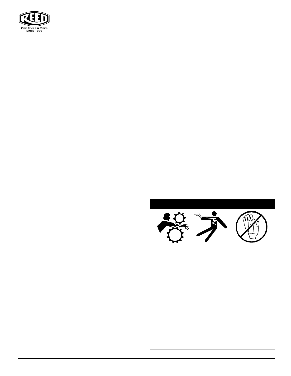
5. Use safety equipment. Always
wear eye protection. Dust mask,
non-skid safety shoes, hard hat, or
hearing protection must be used for
appropriate condition
6. Operate machine from side with REV/OFF/FOR
switch.
s.
0416-55301
3
Page 4
launaM s’rotarepO evirD rewoP DP1035
TOOL USE AND CARE
1. Use clamp or other practical way to secure and support the workpiece to a stable platform. Holding the
work by hand or against your body is unstable and may
lead to loss of control.
2. Do not force tool. Use the correct tool for your applica-
tion. The correct tool will do the job better and safer at
the rate for which it is designed.
3. Do not use tool if switch does not turn it ON or OFF.
Any tool that cannot be controlled with the switch is dangerous and must be repaired.
4. Disconnect the plug from the power source before
making any adjustments, changing accessories, or
storing the tool.
Such preventive safety measures re-
duce the risk of starting the tool accidentally.
Store idle tools out of the reach of children and other
5.
untrained persons. Tools are dangerous in the hands
of untrained users.
6. Maintain tools with care. Keep cutting tools sharp and
clean. Properly maintained tools with sharp cutting edges
are less likely to bind and are easier to control.
7. Check for misalignment or binding of moving parts,
breakage of parts, and any other condition that may affect the tool’s operation. If damaged, have the tool
serviced before using. Many accidents are caused by
poorly maintained tools.
8. Use only accessories that are recommended by the
ma
nufacturer for your model. Accessories that may
be suitable for one tool may become hazardous when
used on another tool.
9. Inspect tool and extension cords periodically and re-
place if damaged. Damaged cords increase the risk of
electrical shock.
10. Keep handles dry and clean; free from oil and grease.
Allows for better control of the tool.
11. Store tools in dry place. Such measures reduce risk of
electrical shock.
SERVICE
1. Tool service must be performed only by qualified repair personnel. Service or maintenance performed by
unqualified repair personnel could result in injury.
2. When servicing a tool, use only identical replacement
parts. Follow instructions in the Maintenance section of
this manual. Use of unauthorized parts or failure to follow maintenance instructions may create a risk of
electrical shock or injury.
3. Follow instructions for lubricating and changing
accessories. Accidents are caused by poorly maintained
tools.
SPECIFIC SAFETY INFORMATION
The Operator’s Manual contains specific safety information
and instructions for your protection against serious injuries
including:
• Loss of fingers, hands, arms or other body parts if clothing or glov
• Electric shock or burns from contact with wires, motor or
other power drive parts:
• Impact injuries, including broken bones if machine tips
over or workpiece falls;
• Eye injuries, including being blinded by the workpiece or
workpiece chips.
• Read and follow safety labels on machine.
• Know the location and functions of all controls before
using.
FOOT SWITCH SAFETY
The foot switch increases safety. The switch shuts off the
motor upon removing your foot. Clothing caught in a rotating
tool can pull the operator into the machine. Additionally, the
machine’s high torque could crush or break bones should
caught or trapped clothing bind around your arm or other body
parts.
CLOTHING/GLOVES CAN BE CAUGHT IN MOVING PARTS.
FINGERS, HANDS, ARMS OR OTHER BODY PARTS CAN
BE CRUSHED OR BROKEN.
• Make sure switch is in the OFF position before plugging in
power cord.
• Use foot switch.
• Do not wear gloves.
• Keep sleeves and jacket buttoned.
• Do not reach across machine. Clothing can be drawn
into moving parts.
• Operate machine from switch side only.
• Do not block or disconnect foot switch.
• Keep foot switch in working order.
• Make sure you can quickly remove your foot from foot switch.
• Keep hands away from rotating pipe and fittings. Stop
machine when screwing fittings on pipe or wiping threads.
es get caught in moving parts;
WARNING
4
0416-55301
Page 5
launaM s’rotarepO evirD rewoP DP1035
THREADING MACHINE SAFETY
1. Machine is made to thread and cut pipe or bolt. Machine also powers roll grooving equipment. Follow in-
structions in Operator’s Manual on machine uses. Do not
use power drives for other jobs including hole drilling, winch
turning, and making/breaking fittings. Other uses may increase the risk of injury.
2. Secure machine to bench or stand. This prevents tipping.
3. Support long heavy pipe with pipe supports. This prevents tipping.
4. Do not wear gloves or loose clothing. Keep sleeves and
jackets buttoned. If clothing should become caught in the
machine, it will continue to wind up, pulling you into the
machine and possibly resulting in serious injury.
5. Do not reach across the machine or pipe. Operating the
machine from the side with
REV/OFF/FOR
switch elimi-
nates reaching across.
6. Do not use machine if foot switch is broken or absent.
The foot switch works as a safety device in preventing
serious injury.
7. Tighten chuck handwheel and engage rear centering de-
vice on the pipe before starting the machine.
8. Keep hands away from rotating pipe and fittings. Let
the machine stop completely before touching the work. Wipe
threads and attach fittings only after the machine stops.
9. Keep covers
in place. Exposed moving parts may offer a
chance for clothing or body parts to become caught in
the machinery.
MACHINE MAINTENANCE
1. Use sharp cutting tools.
2. Grease front and rear bearings every 8 hours of use.
3. Inspect machine cord. Replace damaged, frayed, bro-
ken or worn machine cord.
4. Inspect extension cords. Repair or replace damaged,
frayed, broken or worn cords.
5. Keep handles dry and clean. Keep free from oil and
grease.
6. When not being used, store machine in a secured,
locked area, out of reach of
children and people unfamiliar
with the threading
machine.
7. Keep foot switch in
working order.
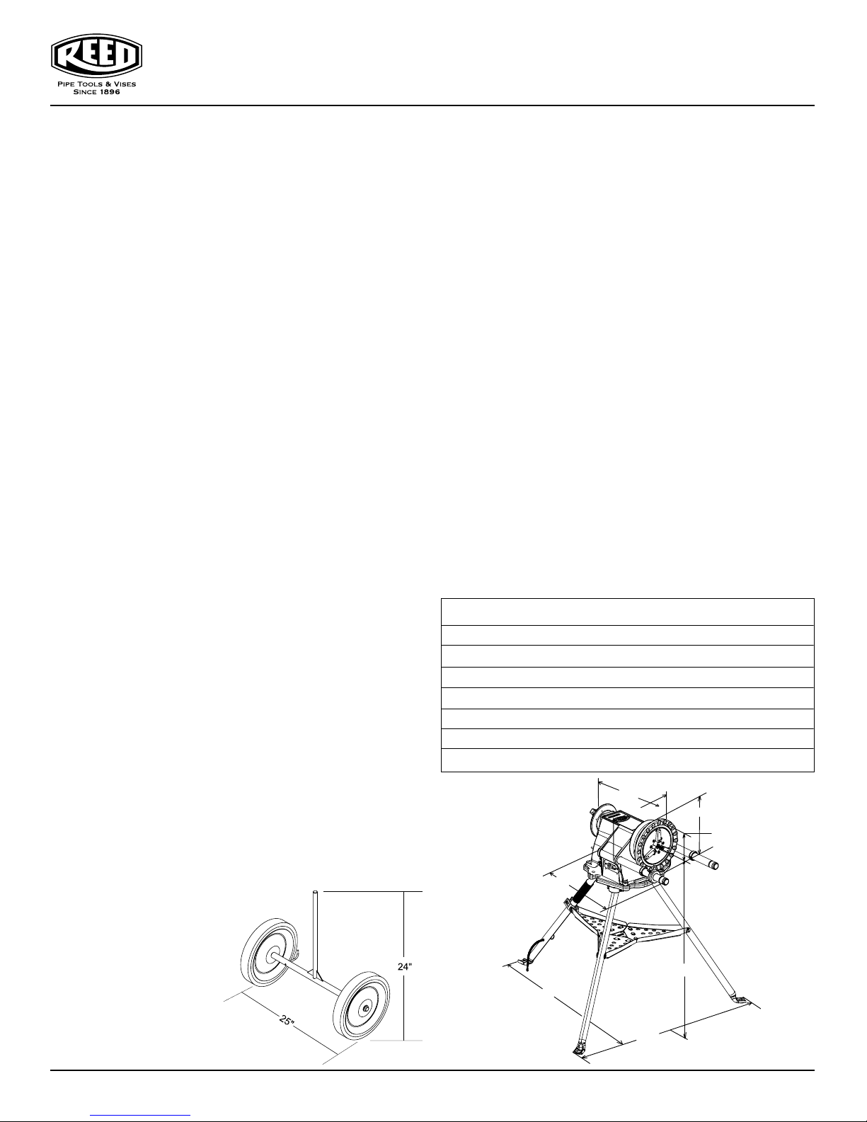
05306
Transporter
DESCRIPTION, SPECIFICATIONS
AND ACCESSORIES
DESCRIPTION
The REED 5301PD Power Drive is an electric-motor-driven
power drive which centers and chucks pipe and conduit and
rotates it while cutting, threading, and reaming operations are
performed. FORWARD (clockwise) rotation can be selected
with the REV/OFF/FOR switch.
SPECIFICATIONS
T
hreading Capacity:
Pipe ...........................1/8” through 2”
Bolt ............................1/4” through 2”
Chuck:............................. Chuck with replaceable jaw inserts.
Rear Centering Device:.. Cam action rotates with chuck
Support Bar (2):.............. Heavy-duty
Swit
ch (REV/OFF/FOR).. Heavy-duty, bump-proof and
reversible
Motor: Universal Type
Horsepower................ 1/2HP
Volts............................120 VAC single phase 60 Hz
Foot Switch (ON/OFF):... Oil and water tight
5301PD Weight: ............... 90 lbs. (40.9 Kg)
ACCESSORIES
05305 Tripod - folding stand with tray (29 lbs.)
05306 Transporter provides effortless power drive portability
05307 Carriage with lever (holds die head, cutter and reamer)
05308 Reamer positive locking, 5 flute cone, right hand
05309 Cutter full-floating, wheel-type wide roll 1/8" through 2"
05380 R811 Universal Die Head (quick-opening die head)
06150 Oiler - stops oil waste, keeps dies flooded
16 3/4"
15 3/4"
19"
39 1/2"
13 1/4"
5 1/2"
36 3/4"
0416-55301
Figure 1
45 3/4"
5
Page 6
launaM s’rotarepO evirD rewoP DP1035
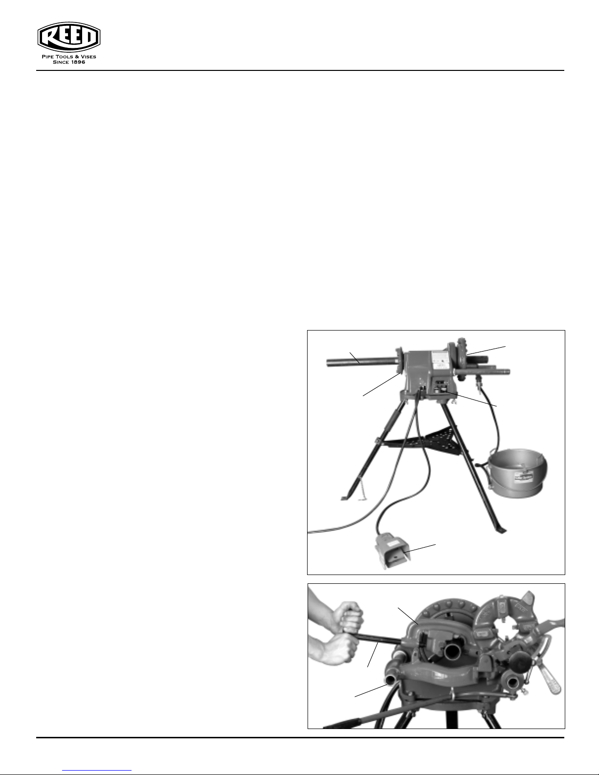
OPERATION USING HAND TOOLS
WARNING: OPERATOR SHOULD BE THOROUGHLY
FAMILIAR WITH PRECEDING SAFETY PRECAUTIONS
BEFORE ATTEMPTING TO OPERATE THIS EQUIPMENT.
INSTALLING PIPE IN POWER DRIVE
1. Measure and mark length of pipe being worked.
2. If pipe is long enough to be retained by centering device,
insert pipe through front or rear of machine. If pipe is
short, insert into front of machine.
3. Make certain that pipe is centered in centering device, if
used, and tighten centering device.
4. Tighten CHUCK JAWS with a repetitive, counter-clock
wise snap spin of HANDWHEEL. This hammering action tightens jaws on pipe. A clockwise rotation snap spin
releases jaws.
CUTTING PIPE WITH HAND CUTTER
1. Install pipe.
2. Engage pipe cutter with pipe and align cutter wheel with
mark on pipe.
3. Rest PIPE CUTTER frame on SUPPORT BAR
(Figure 4) located on switch side of machine. Tighten
FEED SCREW HANDLE.
4. With power cord plugged in, turn
FOR (forward) position.
5. Place foot on FOOT SWITCH (Figure 2) to operate
machine.
6. Continuously tighten feed screw handle (Figure 3) with
both hands until pipe cutoff is completed.
7. Release foot switch and turn
OFF position.
REAMING PIPE WITH HAND REAMER
NOTE: SPIRAL SELF FEEDING REAMERS ARE NOT SUITABLE FOR POWER DRIVE USE.
1. Turn
2. Insert reamer into end of pipe and hold firmly onto
3. Step on foot switch and push on reamer handgrip
4. Release foot switch, remove reamer and turn
REV/OFF/FOR switch to FOR (forward position).
and handgrip (Figure 5).
(Figure 5) with right hand to ream pipe.
switch to OFF position.
REV/OFF/FOR switch to
REV/OFF/FOR switch to
handle
REV/OFF/FOR
port bar (Figure 4) located on switch side.
2. Place 06150 Oiler (Figure 6) under threader and apply
REED Thread Cutting Oil on pipe end.
3. Turn REV/OFF/FOR switch to FOR (forward) position.
4. Step on foot switch and push threader (Figure 4) with
right hand to engage dies.
NOTE: THREADER IS AUTOMATIC ONCE DIES ARE
ENGAGED. APPLY PLENTY OF OIL (FIGURE 6) UNTIL
THREADS ARE COMPLETED.
5. Release foot switch once threads are completed.
6. Push back support bar (Figure 4) on switch side.
7. Reverse THREADER RATCHET KNOB.
8. Lower threader handle and pull support bar out. Threader
handle is now against lower side of support bar.
9. Turn
REV/OFF/FOR switch to REV (reverse) position
and back off threader by stepping on foot switch.
10. Release foot switch and turn
REV/OFF/FOR switch to
OFF position.
Pipe
Centering
Head
Foot
Switch
Chuck Jaw
Handwheel
REV/OFF/FOR
Switch
Figure 2
Pipe
Cutter
Feed Screw
Handle
THREADING PIPE WITH HAND THREADER
1. Place threader on end of pipe with handle resting on sup-
6
Support
Bar
Figure 3
9416-55301
Page 7
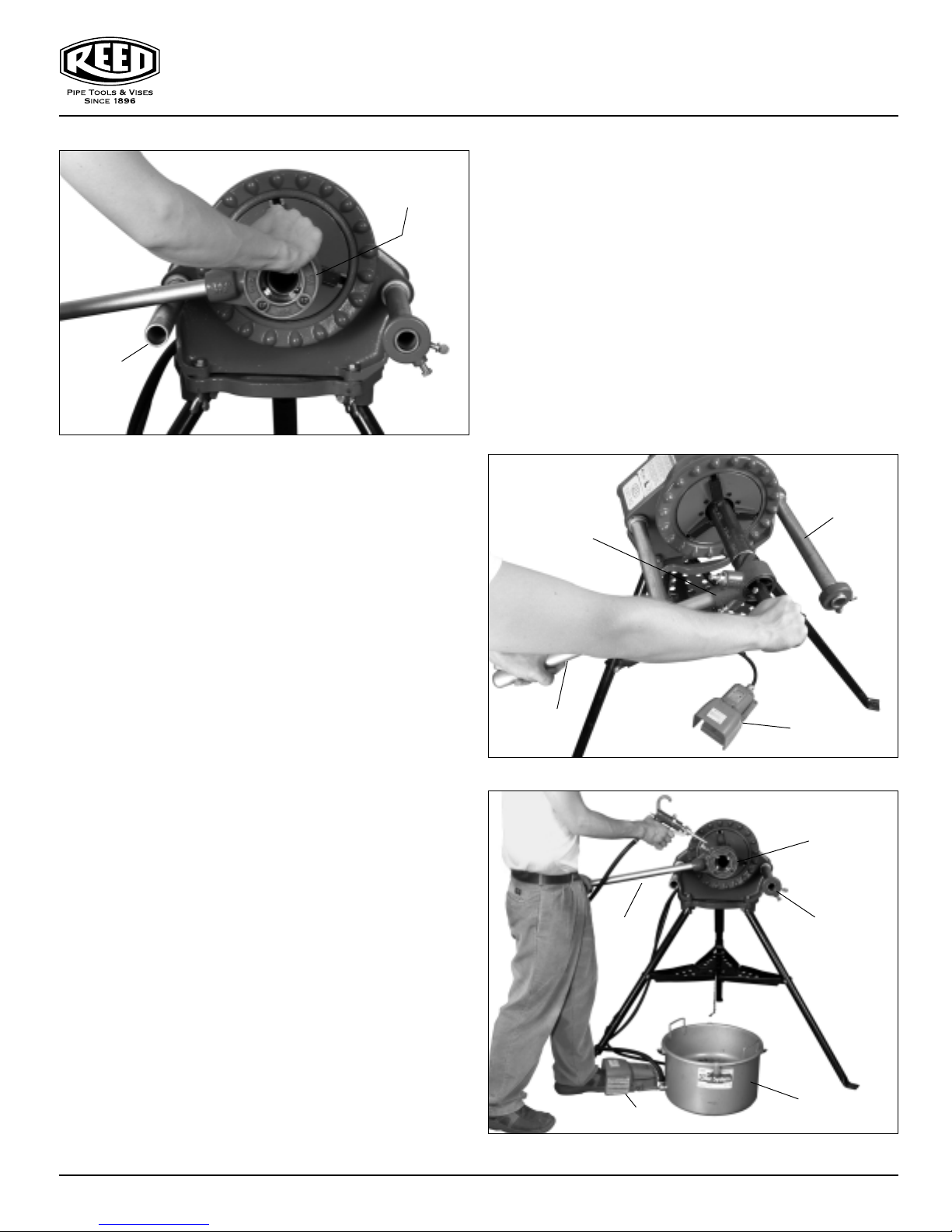
Support
Bar
Figure 4
Hand
Threader
Cutting Pipe with 05309 Cutter
1. Swing reamer and threader back to out-of-way position.
2. Move pipe cutter down onto pipe and move carriage with
carriage lever to line up cutter wheel with mark on pipe
(Figure 8).
3. Tighten cutter feed screw handle on pipe.
4. Turn
5. Continuously turn cutter feed screw handle with both
6. Release foot switch and turn
7. Return pipe cutter to out-of-way position.
REV/OFF/FOR switch to FOR (forward) position and step
on foot switch.
hands until pipe is cut off.
REV/OFF/FOR switch to OFF
position.
launaM s’rotarepO evirD rewoP DP1035
OPERATION USING
POWER DRIVE MOUNTED TOOLS
WARNING:
OPERATOR SHOULD BE THOROUGHLY FAMILIAR WITH
SAFETY PRECAUTIONS BEFORE ATTEMPTING TO OPERATE THIS EQUIPMENT.
CORRECT OPERATING POSITION FOR CUTTING,
THREADING AND REAMING IS TO STAND ON THE
SWITCH SIDE OF THE POWER DRIVE, WITH LEFT FOOT
OPERATING FOOT SWITCH. (FIGURE 6)
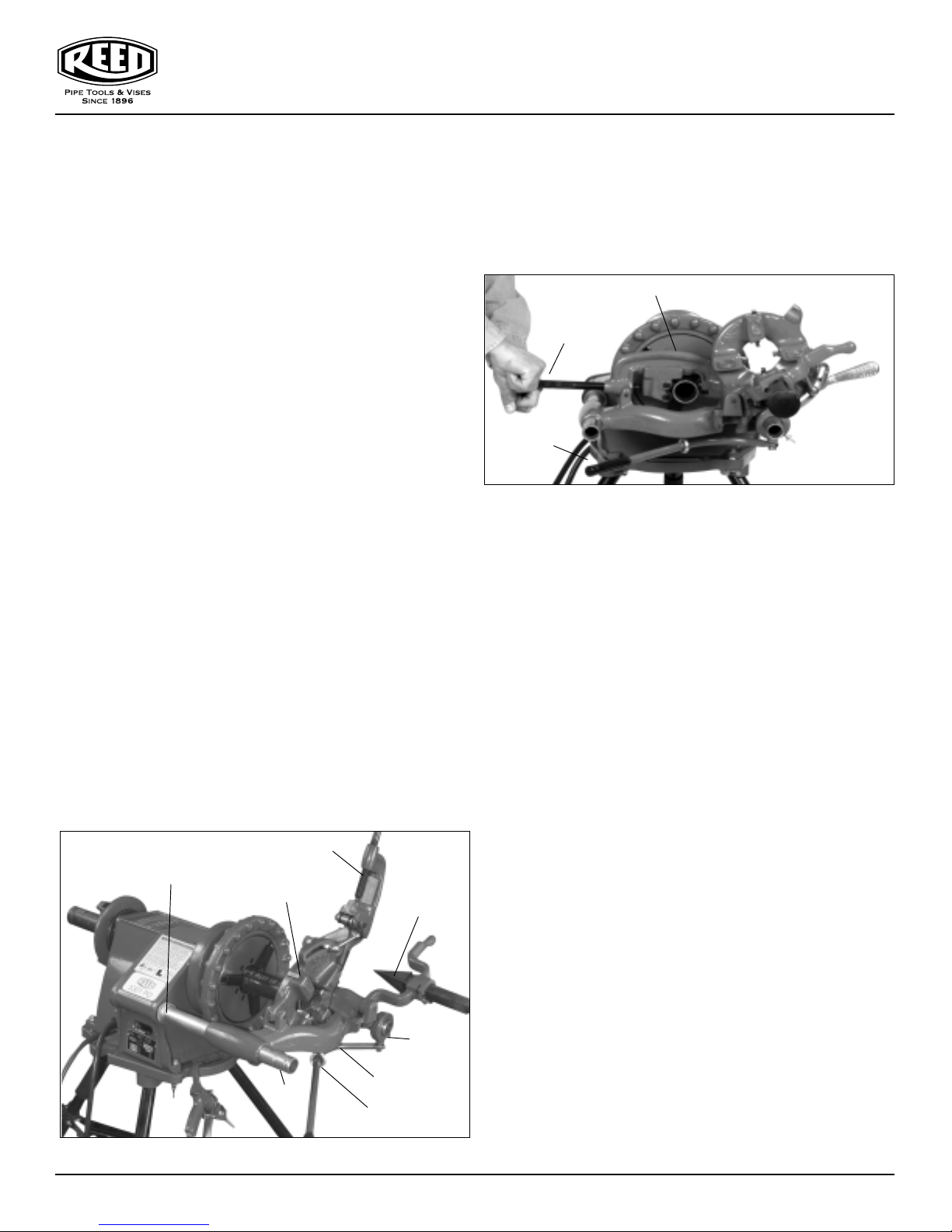
Installing 05307 Carriage, Die Head, 05308
Reamer and 05309 Cutter
1. Pull two support bars on power drive forward (Figure 7).
2. Slide two retaining ring assemblies against power drive
body and secure with two set screws.
3. Secure eyebolt assembly to 05307 Carriage.
4. Slide lever arm through eyebolt assembly and secure to
collar assembly with shoulder bolt.
5. Slide 05307 Carriage and collar assembly onto support
bars.
6. Tighten collar assembly thumb screw into groove on
support bar.
7. Insert die head post into mating hole in carriage.
NOTE: WHEN FULLY INSERTED, SPRING LOADED BALL
WILL HOLD DIE HEAD IN PLACE.
8. Install cutter and reamer and secure with pins.
9. Install pipe.
10. Position oiler under pipe.
Handle
Figure 5
Figure 6
Hand
Reamer
Handle
Foot Switch
Support
Bar
Foot
Switch
Hand
Threader
Support
Bar
Oiler
0416-55301
7
Page 8
launaM s’rotarepO evirD rewoP DP1035
Reaming Pipe with 05308 Reamer
1. Swing die head and cutter back to out-of-the-way
position (Figure 10).
2. Move reamer arm down into reaming position.
3. Extend reamer by pressing latch and sliding knob
toward pipe until latch engages bar.
4. Turn
REV/OFF/FOR switch to FOR and complete reaming
by pushing carriage lever with right hand.
5. Position reamer into pipe and complete reaming by pushing carriage lever with right hand.
6. Retract reamer bar and return reamer to out-of-way
position.
7. Release foot switch and turn
REV/OFF/FOR switch
to OFF position.
8. Release speed chuck handwheel and centering head
from pipe.
9. Remove pipe.
Threading Pipe with the R811 Die Head
1. Install die set. Refer to “Installing Dies” (page 8)
procedure.
2. Swing cutter and reamer to out-of-way position
3. Lower die head into threading position.
4. Apply Reed Threadguard Cutting Oil to pipe end.
5. Turn
REV/OFF/FOR switch to FOR position and step
on foot switch.
6. Engage dies with pipe using carriage lever and oil dies
with plenty of Reed Threadguard Cutting Oil until
thread is completed.
7. When thread is complete, raise throwout lever to the
Die Head
Support
Bar
Cutter
Retaining
Ring
Figure 7 - 5301PD Power Drive with accessories.
(Figure 9).
Reamer
Collar
Assembly
Carriage
Eye Bolt
open position, retracting the dies on the R811
Universal Die head.
8. Release foot switch and turn
REV/OFF/FOR switch to
OFF position.
9. Move carriage lever away from pipe end and return die
head to up and out-of-way position.
Cutter
Feed Screw
Handle
Carriage
Lever
Figure 8 - Cutting pipe with cutter
Installing Dies in the R811 Universal Die Head
The R811 Universal Die Head requires one set of 4 Universal
Dies to thread pipe ranging from 1/8" to 2". One set of dies is
required for each of the following pipe size ranges:
1/8"
1/4" and 3/8"
1/2" and 3/4"
1" through 2"
NOTE: BOLT THREADING REQUIRES A SEPARATE SET
OF DIES FOR EACH BOLT SIZE.
1. Lay die head on bench with numbers face up.
2. Flip throwout lever to OPEN position.
3. Loosen clamp lever approximately three turns.
4. Lift tongue of clamp lever washer up out of slot under
size bar. Slide throwout lever all the way to end of slot
in the OVER direction indicated on size bar.
5. Remove dies from die head.
6. Die numbers 1 through 4 must agree with those on die
head.
7. Insert dies to mark on side of die head.
8. Slide throwout lever back so that tongue of clamp lever
washer will drop in slot under size bar.
9. Adjust die head size bar until index line on lock screw
or link is aligned with proper size mark on size bar.
10. Tighten clamp lever. For bolt threads, align index line
with bolt line on size bar.
11. If oversize or undersize threads are required, set the
index line in direction of OVER or UNDER size mark on
size bar.
8
0416-55301
Page 9
MAINTENANCE INSTRUCTIONS
WARNING: ALWAYS UNPLUG POWER CORD BEFORE
SERVICING POWER DRIVE.
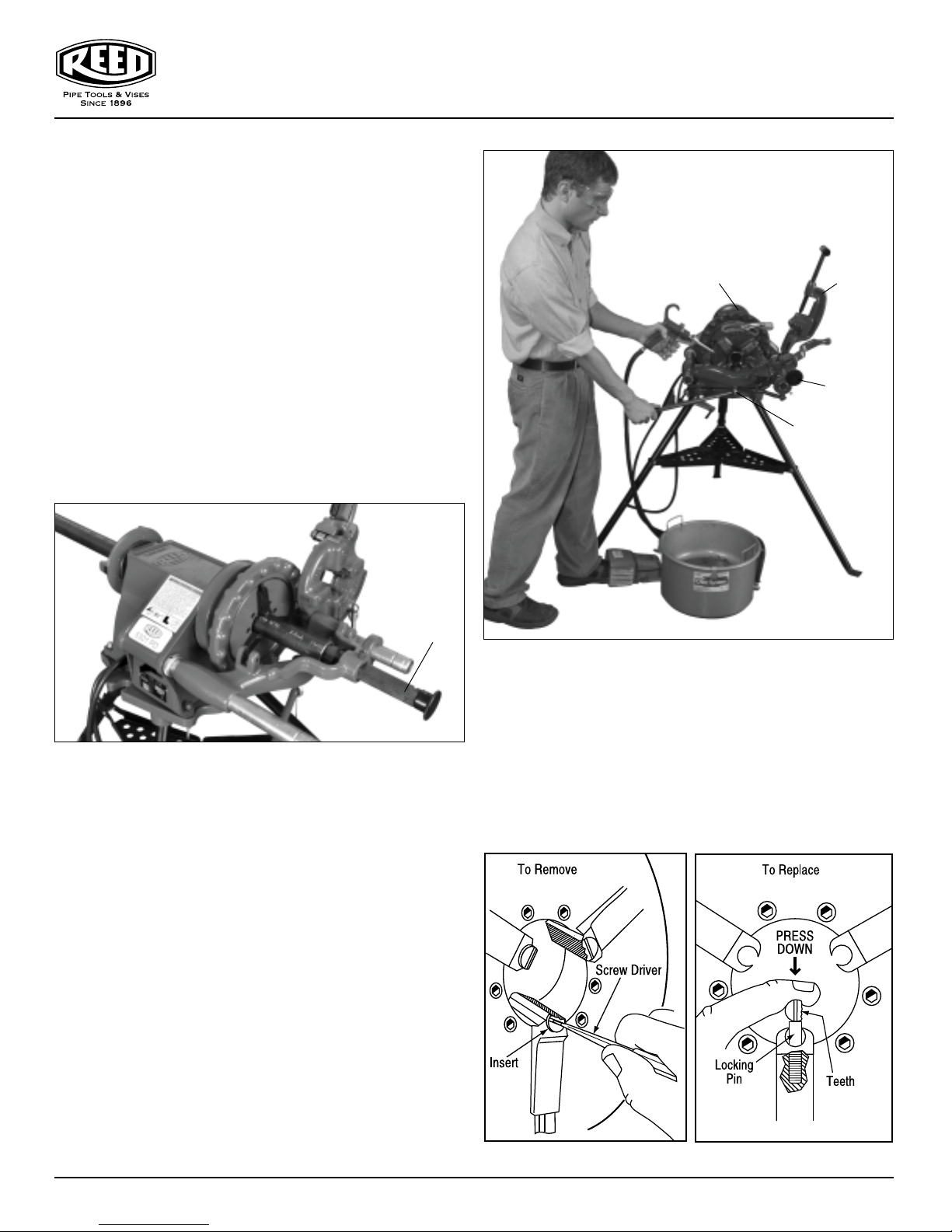
JAW INSERT REPLACEMENT
IMPORTANT: WHEN TEETH ON JAW INSERTS BECOME
WORN AND FAIL TO HOLD PIPE OR ROD DURING OPERATION, REPLACE ENTIRE SET OF JAW INSERTS.
CLEAN TEETH OF JAW INSERTS DAILY WITH WIRE
BRUSH.
1. Place screw driver in insert slot and turn 90 degrees in
either direction (Figure 11).
2. Place insert sideways on locking pin and press down as
far as possible.
3. Hold insert down firmly with screwdriver, turn teeth
face up.
Die
Head
launaM s’rotarepO evirD rewoP DP1035
Cutter
Reamer
Carriage
Lever
Reamer
in position
Figure 10
LUBRICATION
Proper lubrication is essential to trouble-free operation and
long life of power drive.
Grease main shaft bearing (#95414, #95415) every 2 to 6
months depending on amount of power drive use. Grease
fittings are provided on side base, one at each end of shaft.
Use a good grade of cup grease.
MOTOR BRUSH REPLACEMENT
Check motor brushes (#95458) every 6 months and replace
when worn to less than 1/2 inch. If commutator (#95420) is
worn, turn outer dimension of commutator and undercut mica
before replacing brushes.
Figure 9 - Threading Pipe with R811 Die Head
MOTOR REPLACEMENT
WARNING: ALWAYS UNPLUG POWER CORD BEFORE
SERVICING POWER DRIVE.
1. Unplug motor receptacle from switch box.
2. Remove 2 screws (#35411) holding motor.
3. Loosen lock screw (#35403) in body at neck of motor
and lift motor out.
0416-55301
Figure 11
9
Page 10
.
D
n
I
Qty.
Ref
.
n
Q
.
D
iption
Qty
S
D
3
0
6
2
R
35401
6
3
D
9
0
T
95882
5
B
G
35406
3
6
S
N
95411
3
7
SCRO
R
95412
1
8BAC
E
95401
9
G
95414
1
0
BODY95571
11
G
0338
1
T
G
9
3
S
W
35404
G
9
5
5
G
95427
1
16
S
W
35412
3
S
W
35413
3
18
N
35415
3
9
D
T
95413
1
20
RING GEAR
95409
1
9
3
2
SCRO
T
95404
1
23
CAP95405
1
BOLT,
S
3
25
95552
1
26
T
95421
3
95422
3
8
CO
G
95451
3
9
S
R
9
3
30
S
G
95424
31
R
Y
9
0
32
R
35429
1
33
BO
S
3
3
3
S
E
95423
1
3
SCREW
35407
2
36S
3
3
X
35416
3
F
R
3
1
39LOC
R
30033
0
UT
338
BO
CS
35
5
G
G
35450
2
D
W
37710
3
95418
R
95578
1
:
9
,
95569
3
5
6
7
8
9
1
3
2
3
31
36
32
33
4
15
9
2
1
2
23
2
8
26
16
18
M
46
3
3
0
44
4
4
Y
CO
T
9
4
R
9
6
#
43540
43525
k
4
5
4
5
5
25
5
k
k
k
k
5
k
k
k
6500
k
095
0
6860
5
33785 5/Pk
30027
k
5300 5/
300
k
0
3
7
89150
Ridg
#
Ridg
#
8
0
35
8
OLL
/
JAW
A
.
9548
48
MOUNTING
NOT SHOWN
7, 38, 39, 4
4
35
launaM s’rotarepO evirD rewoP DP1035
7
5301PD
Power Drive
1
0
0
5
2, 43
9
1
1
0
2
2
Ref. No
1
1
1
1
1
OTOR ASSEMBLY
Parts List
escriptio
CREW, SLOTTE
LOCK WASHE
CENTERING HEA
REAR JAW SE
ALL BEARIN
TEP PI
LL, REA
K PLAT
REAR BEARIN
REASE FITTING4
HRUST RIN
ET SCRE
FRONT BEARIN
DRIVE RIN
ET SCRE
ET SCRE
DRIVE DOWEL PI
RIVE SHAF
tem Code
540
540
5419
541
540
ELECTRICAL ASSEMBL
id
46790 6/P
40270 6/P
43735
4
45260 5/P
44
4374
4
4534
45265 3/P
4
22 3/P
4410
001
Pk
. No
2
2
2
4
5
7 BOLT, HE
8
4
4
Descriptio
LL, FRON
SHC
JAW SET, FRONT
JAW INSER
MPRESSION SPRIN
UPPORT BA
PRING RIN
ETAINING RING ASSEMBL
LOCK WASHE
LT, SHC
TRAIN RELIEF PLAT
CREW
LAT WASHE
K WASHE
WING N
LT, SH
Item Code
54056
548
588
540
5408
001
2
2 4
411
ty.
2
4
4
Ridgid
45295 6/P
44090
471
442
4452
447
4582
44735 5/P
45280
46670 5/P
44230 5/P
40930 5/P
4538
46745 5/P
2
Ref. No
4
4
44 WARNING STICKE
4
46
4
BODY BEARINGS AND HARDWARE INCLUDES
, 10, 11, 14, 39, 40, 41, 45, 46
escr
RIVE SCRE
REASE FITTIN
RD GROMME
EAR JAW ASSEMBLY
FRONT HANDWHEEL SCR
Item Code
5429
547
SSEM
.
4
4
5
id
869
467
RIDGID® is a registered trademark of RIDGID, Inc. and is not associated with Reed Manufacturing Company
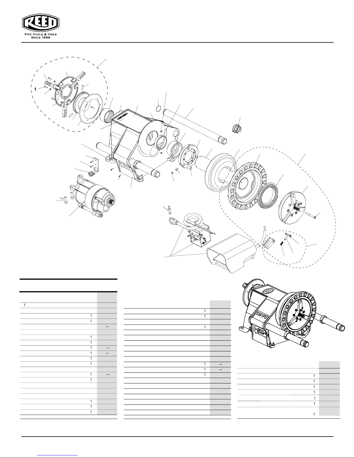
10
See also RP #86
0416-55301
Page 11
35
25, 26
30
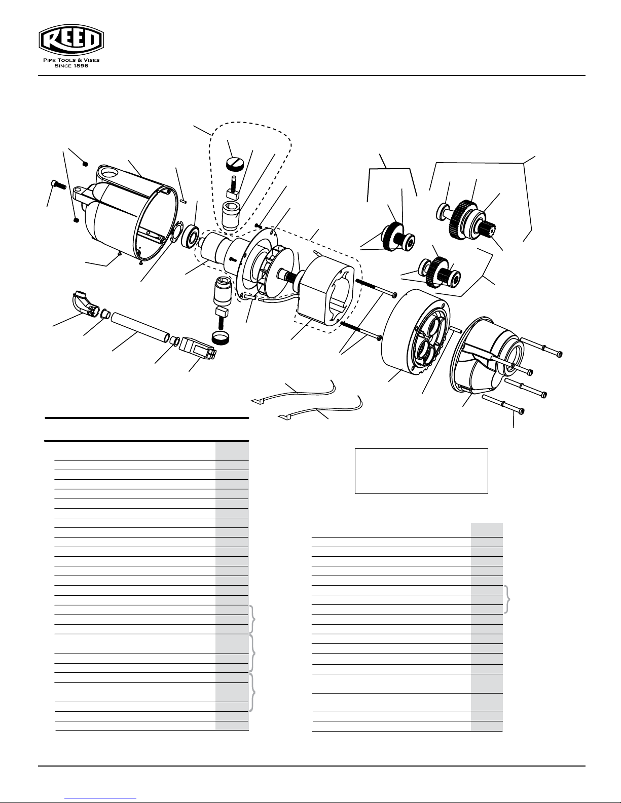
launaM s’rotarepO evirD rewoP DP1035
5301PD
Motor Assembly
43
34
33
4
10
32
37
12
31
44
12
11
13
15
40
18
17
15
16
20
15
19, 21
42
23
14
22, 24
41
1
36
2
36
Parts List
Ref. No.
1
2
3
4
5 FAN HOUSING 95407 1
6 GEAR COVER 95408 1
7 LOCK WASHER 35428 4
8 SCREW 35427 4
9
10
11
12 BEARING 98855 2
13 FINGER DISK SPRING 95445 1
14
15 BEARING 98846 5
16 GEAR SHAFT - 1ST 95446 1
17 SPUR GEAR 98809 1
18 KEY 48807 1
19
20 SPUR GEAR 95447 1
21 KEY 48810 1
22 GEAR SHAFT - 3RD 95450 1
23 SPUR GEAR - 38 RPM 95449 1
24 KEY 48816 1
25 NAME PLATE 95456 1
26
Description
90° CONNECTOR
CONDUIT
PLUG
MOTOR HOUSING
DOWEL PIN
DOWEL PIN
ARAMATURE W/FAN
BEARING
GEAR SHAFT - 2ND- 38 RPM
DRIVE SCREW
- 57 RPM
- 57 RPM 95563
Item Code
95452 1
95453 1
95454 1
95406 1
95417 1
35430 1
95572 1
98845 1
95448 1
95564
30133 2
29
27
28
3
38
5
9
6
39
7, 8
Qty.
1
1
Ridgid #
46900
—
46830
—
43165
42875
45150 5/Pk
45075 5/Pk
—
—
44010
44565
44580
45315
45060
44985
44985
44985
45005
45005
45005
45005
45370
45370
45370
45370
—
85920 5/Pk
See
Ref. No. 40
See
Ref. No. 41
See
Ref. No. 42
Ref. No.
27 FIELD 95573 1
28 FIELD SCREW 98848 2
29 INSULATOR TUBE 98885 2
30 SET SCREW 30018 2
31 FAN PLATE 95474 1
32 BRUSH HOLDER 95455 2
33 BRUSH ASSEMBLY, PAIR 95570 1
34 BRUSH CAP 95459 2
35 LOCK SCREW 35435 1
36 BUSHING PLASTIC 35434 2
37 SCREW 35449 3
38
BRUSH LEAD, RED w/TERMINAL 95580 1
39
BRUSH LEAD, WHITE w/TERMINAL 95579 1
40
41
42
43
BRUSH/HOLDER/CAP ASSEMBLY 95585 2
44
Complete Motor Assembly
38 RPM 95481
57 RPM 95499
57 - RPM
57 RPM
Item Code
95478 1
95479 1
95549 1
95480 1
95550
Description
SHAFT ASSEMBLY 1
SHAFT ASSEMBLY 2 - 38 RPM
SHAFT ASSEMBLY 3 - 38 RPM
FIELD & ARMATURE 95587 1
Qty.
1
Ridgid #
86690 2/Pk
44555 2/Pk
—
39770 5/Pk
—
—
44540
—
—
—
—
—
—
44985
45005
45370
See
Ref. No. 43
RIDGID® is a registered trademark of RIDGID, Inc. and is not associated with Reed Manufacturing Company
0416-55301
11
Page 12
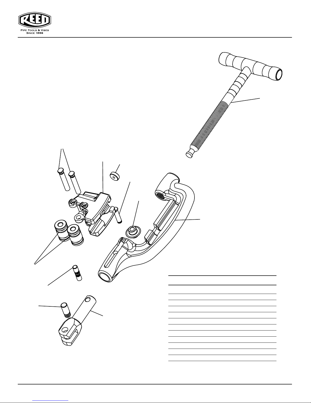
5301PDPC #05309
5301PD Cutter Adapter
6
launaM s’rotarepO evirD rewoP DP1035
2
4
11
10
3
9
7
5
1
Parts List
Ref. No. Description Item Code Qty. Used
1 Body 95488 1
2 Screw Assembly 93681 1
3 Slide 95489 1
8
4 Roller 95490 2
5 Cutter Wheel 03612 1
6 Pin 95491 2
7 Cutter Wheel Pin 93310 1
8 Yoke 95468 1
9 Trust Washer 93679 1
10 Knurled Pin 95560 1
11 1/ 2 x 1-1/4 Pin 95561 1
12
0416-55301
Page 13
launaM s’rotarepO evirD rewoP DP1035
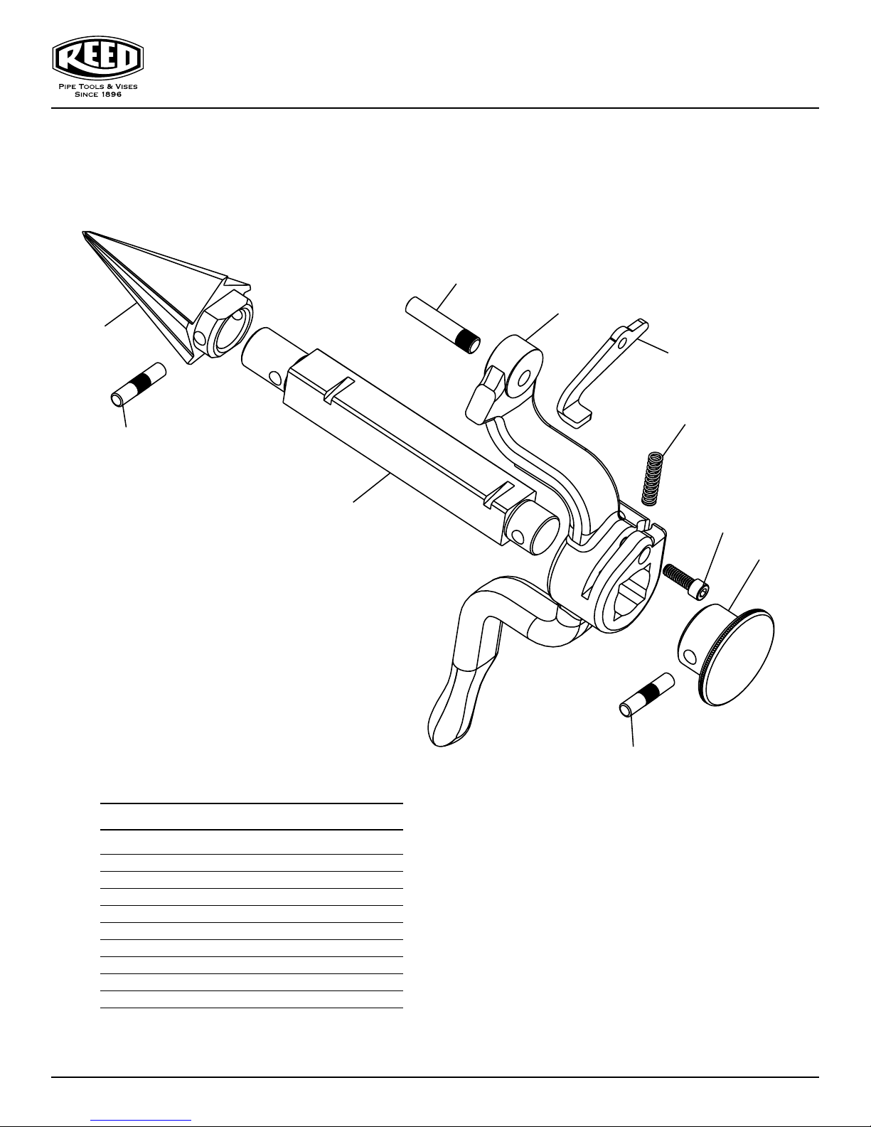
5301PDR #05308
5301PD Reamer Adapter
6
1
2
7
9
5
3
Parts List
Ref. No. Description Item Code Qty. Used
1 Arm 95487 1
2 Reamer 95492 1
3 Bar 95493 1
4 Knob 95494 1
5 Pin 95495 2
6 Hinge Pin 95496 1
7 Latch 95497 1
8 1/4 x 3/4” Pin 30004 1
9 Spring 95451 1
8
4
5
0416-55301
13
Page 14
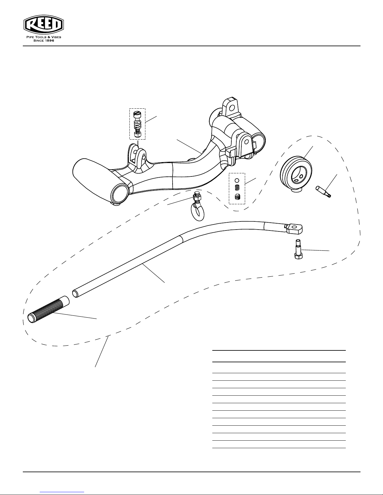
CARRIAGE #05307
5301PD Carriage Adapter
launaM s’rotarepO evirD rewoP DP1035
8
1
2
4
9
5
3
6
7
10
14
Parts List
Ref. No. Description Item Code Qty. Used
1 Carriage 95465 1
2 Collar 95410 1
3 Shoulder Bolt 35424 1
4 Thumb Screw 35425 1
5 Eye Bolt 45550 1
6 Lever Arm 95551 1
7 Grip 92754 1
8 Stop Bolt Assembly 95881 1
9 Ball Retainer Kit 95883 1
10 Leverarm Kit 95885 1
0416-55301
Page 15
launaM s’rotarepO evirD rewoP DP1035
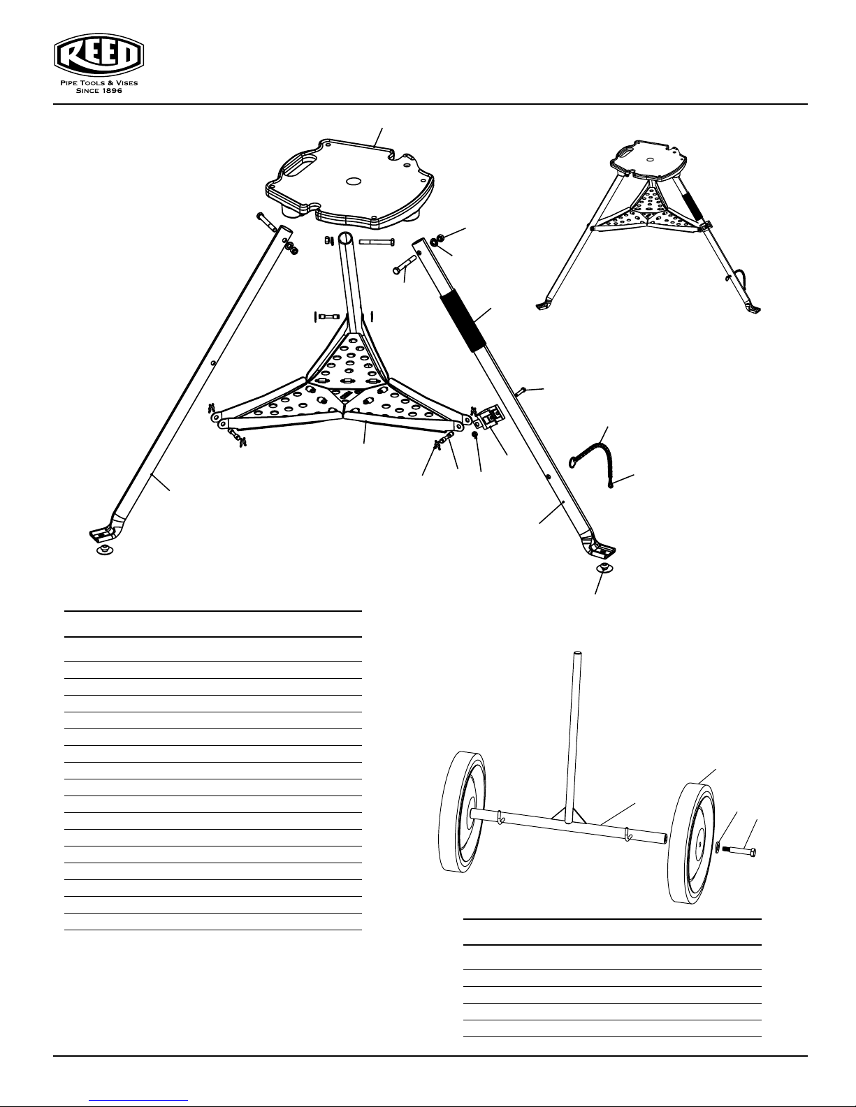
1
5301PDTP #05305
5301PD Tripod
9
Parts List
6
5
4
11
15
12
2
7
8
16
3
14
10
13
Ref. No. Description Item Code Qty. Used
1 5301PD Base 95398 1
2 Tray Assembly 99004 1
3 Tray Support Clamp 40194 1
4 Leg Bolt 30244 3
5 Nut 30032 3
6 Lock Washer 30033 3
7 Tray Pin 99008 6
8 X Washer 99010 2
9 Front Leg 45465 2
10 Rear Leg 45466 1
11 Handle Grip 40183 1
12 Leg Chain Assembly 99055 1
13 Grommet 40171 3
14 Clip 40205 1
15 Screw 39005 1
16 Nut 30123 1
#05306
5301PD Transporter
2
1
4
Parts List
Ref. No. Description Item Code Qty. Used
1 Axle 95559 1
2 Semi-Pneumatic Wheel 95473 2
3 Hex Head Shoulder Screw 35448 2
4 1/2 x 1/8 Flat Washer 38845 2
3
0416-55301
15
Page 16
launaM s’rotarepO evirD rewoP DP1035
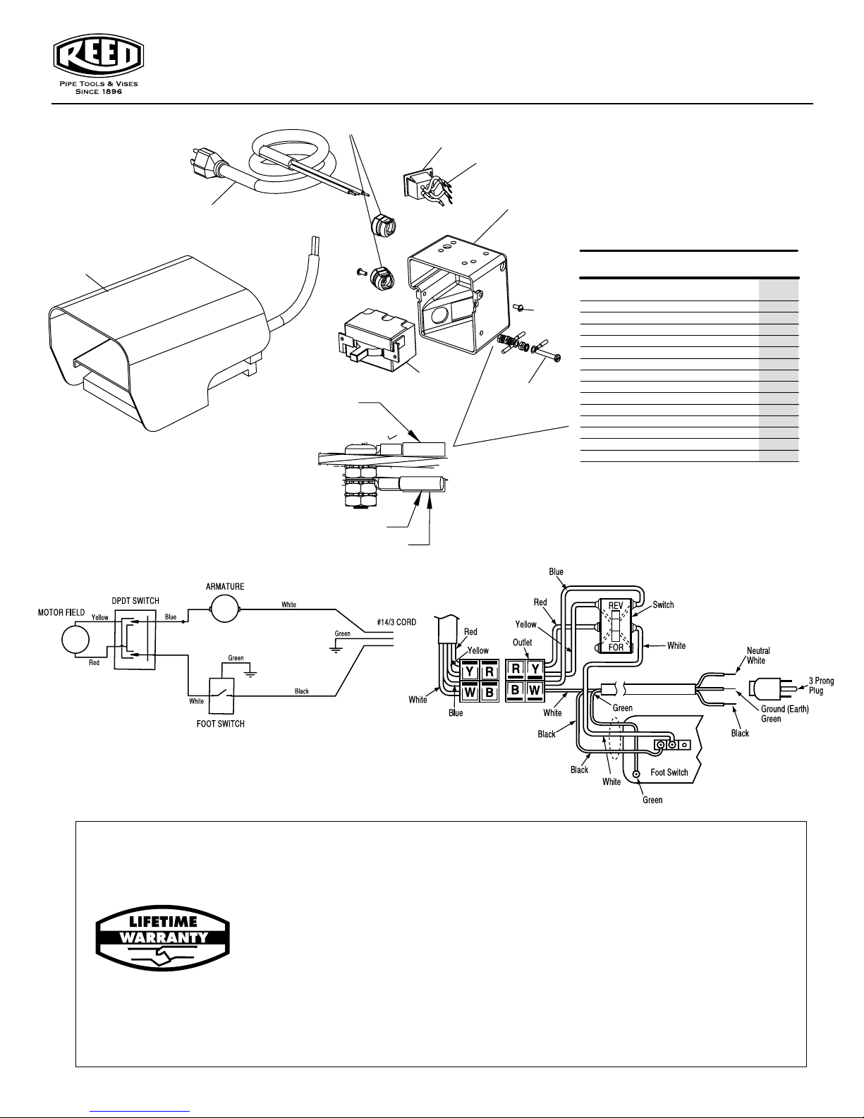
12
5301PD
Wiring Schematic
11
Jumper Wire on Base
Ground Screw Detail
13
Service Cord Ground
Foot Switch Ground
4
14
1
3
2
6, 7, 8
Ground Screw
5301PD
Electrical Assembly
Parts List
Ref. No.
1 SWITCH BOX 95430 1
2 SWITCH 95557 1
3 SCREW 30106 2
4
5 RING TONGUE TERMINAL 98859 3
6 SCREW (GROUND) 30159 1
7 LOCK WASHER 35423 3
8
9 GROUND WIRE 95438 1
10
11 LINE CORD W/PLUG 95432 1
12 FOOT SWITCH W/CORD 95574 1
13 CORD GROMMET 95429 3
14 SPADE TERMINAL 35436 4
RIDGID® is a registered trademark of RIDGID, Inc. and is not
associated with Reed Manufacturing Company
Description
OUTLET JUMPER ASSY.
HEX NUT
SCREW
Item Code
95556 1
30117 3
35431 1
Qty.
Ridgid #
44505
46985 5/Pk
46740
36642
46735
—
—
—
—
—
—
—
—
—
5301PD
Wiring Diagram
Reed Hand Tools are for the professional trade and are warranted against all failure due to defects in workmanship and materials
for the normal life of the tool.
FAILURES DUE TO MISUSE, ABUSE, OR NORMAL WEAR AND TEAR ARE NOT COVERED BY THIS WARRANTY.
Power units for Universal Pipe Cutters, Saw It®, electric test pumps, and threading power drives are warranted for
a period of one year from date of purchase.
NO PARTY IS AUTHORIZED TO EXTEND ANY OTHER WARRANTY. NO WARRANTY FOR MERCHANTABILITY OR FITNESS
FOR A PARTICULAR PURPOSE SHALL APPLY.
No warranty claims will be allowed unless the product in question is received freight prepaid at the Reed factory. All warranty claims
are limited to repair or replacement, at the option of the company, at no charge to the customer. REED IS NOT LIABLE FOR ANY
DAMAGE OF ANY SORT, INCLUDING INCIDENTAL AND CONSEQUENTIAL DAMAGES. Some states do not allow the exclusion or
limitation of incidental or consequential damages, so the above exclusion may not apply.
This warranty gives you specific legal rights, and you may also have other rights which vary from state to state.
16
Reed Lifetime Warranty
0416-55301
 Loading...