

Page 1
®
Visit our website at
www.reebokhomefitness.com
new products, prizes,
fitness tips, and much more!
atent Pending
®
®
P
odel No. RBTL69921
M
Serial No.
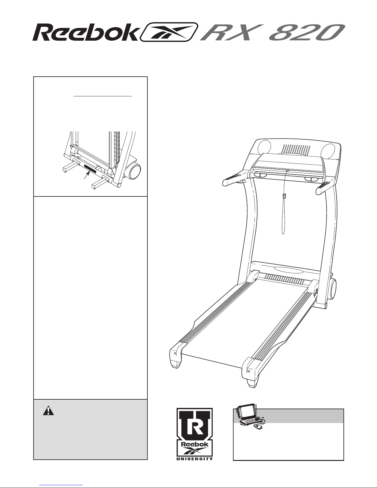
Find the serial number in the location
shown below. Write the serial number
in the space above for reference.
Serial Number
Decal
QUESTIONS?
If you have questions, or if there
are missing or damaged parts,
we will guarantee complete satisfaction through direct assistance from our factory.
USER'S MANUAL
TO AVOID DELAYS, PLEASE
CALL DIRECT TO OUR TOLLFREE CUSTOMER HOT LINE.
The trained technicians on our
Customer Hot Line will provide
immediate assistance, free of
charge to you.
CUSTOMER HOT LINE:
1-800-999-3756
Mon.–Fri., 6 a.m.–6 p.m. MST
CAUTION
Read all precautions and instructions in this manual before
using this equipment. Save this
manual for future reference.
Page 2

TABLE OF CONTENTS
®
IMPORTANT PRECAUTIONS . . . . . . . . . . . . . . . . . . . . . . . . . . . . . . . . . . . . . . . . . . . . . . . . . . . . . . . . . . . . . . . . .3
BEFORE YOU BEGIN . . . . . . . . . . . . . . . . . . . . . . . . . . . . . . . . . . . . . . . . . . . . . . . . . . . . . . . . . . . . . . . . . . . . . . .5
ASSEMBLY . . . . . . . . . . . . . . . . . . . . . . . . . . . . . . . . . . . . . . . . . . . . . . . . . . . . . . . . . . . . . . . . . . . . . . . . . . . . . . .6
HOW TO USE THE CHEST PULSE SENSOR . . . . . . . . . . . . . . . . . . . . . . . . . . . . . . . . . . . . . . . . . . . . . . . . . . .10
OPERATION AND ADJUSTMENT . . . . . . . . . . . . . . . . . . . . . . . . . . . . . . . . . . . . . . . . . . . . . . . . . . . . . . . . . . . .11
HOW TO FOLD AND MOVE THE TREADMILL . . . . . . . . . . . . . . . . . . . . . . . . . . . . . . . . . . . . . . . . . . . . . . . . . .23
TROUBLESHOOTING . . . . . . . . . . . . . . . . . . . . . . . . . . . . . . . . . . . . . . . . . . . . . . . . . . . . . . . . . . . . . . . . . . . . . .24
CONDITIONING GUIDELINES . . . . . . . . . . . . . . . . . . . . . . . . . . . . . . . . . . . . . . . . . . . . . . . . . . . . . . . . . . . . . . .27
ORDERING REPLACEMENT PARTS . . . . . . . . . . . . . . . . . . . . . . . . . . . . . . . . . . . . . . . . . . . . . . . . . .Back Cover
LIMITED WARRANTY . . . . . . . . . . . . . . . . . . . . . . . . . . . . . . . . . . . . . . . . . . . . . . . . . . . . . . . . . . . . . . .Back Cover
Note: A PART LIST/EXPLODED DRAWING is attached in the center of this manual.
REEBOK and the Vector Logo are registered trademarks and service marks of Reebok. This product is
manufactured and distributed under license from Reebok International.
2
Page 3

IMPORTANT PRECAUTIONS
WARNING: To reduce the risk of burns, fire, electric shock, or injury to persons, read the
following important precautions and information before operating the treadmill.
1. It is the responsibility of the owner to ensure
that all users of this treadmill are adequately
informed of all warnings and precautions.
2. Use the treadmill only as described.
3. Place the treadmill on a level surface, with at
least eight feet of clearance behind it and two
feet on each side. Do not place the treadmill
on any surface that blocks air openings. To
protect the floor or carpet from damage, place
a mat under the treadmill.
4. Keep the treadmill indoors, away from moisture and dust. Do not put the treadmill in a
garage or covered patio, or near water.
5. Do not operate the treadmill where aerosol
products are used or where oxygen is being
administered.
6. Keep children under the age of 12 and pets
away from the treadmill at all times.
7. The treadmill should not be used by persons
weighing more than 250 pounds.
8. Never allow more than one person on the
treadmill at a time.
9. Wear appropriate exercise clothes when
using the treadmill. Do not wear loose clothes
that could become caught in the treadmill.
Athletic support clothes are recommended for
both men and women. Always wear athletic
shoes. Never use the treadmill with bare feet,
wearing only stockings, or in sandals.
10. When connecting the power cord (see page 11),
plug the power cord into a surge suppressor
(not included) and plug the surge suppressor
into a grounded circuit capable of carrying 15
or more amps. No other appliance should be on
the same circuit. Do not use an extension cord.
11. Use only a single-outlet surge suppressor that
meets all of the specifications described on
page 10. To purchase a surge suppressor, see
your local REEBOK dealer or call 1-800-8063651 and order part number 146148.
12. Failure to use a properly functioning surge
suppressor could result in damage to the control system of the treadmill. If the control system is damaged, the walking belt may change
speed or stop unexpectedly, which may result
in a fall and serious injury.
13. Keep the power cord and the surge suppressor away from heated surfaces.
14. Never move the walking belt while the power
is turned off. Do not operate the treadmill if
the power cord or plug is damaged, or if the
treadmill is not working properly. (See
BEFORE YOU BEGIN on page 5 if the treadmill is not working properly.)
15. Never start the treadmill while you are standing on the walking belt. Always hold the
handrails while using the treadmill.
16. The treadmill is capable of high speeds.
Adjust the speed in small increments to avoid
sudden jumps in speed.
17. The pulse sensors are not medical devices.
Various factors, including the user's movement, may affect the accuracy of heart rate
readings. The pulse sensors are intended
only as exercise aids in determining heart
rate trends in general.
18. Never leave the treadmill unattended while it
is running. Always remove the key, unplug
the power cord and move the on/off switch to
the off position when the treadmill is not in
use. (See the drawing on page 5 for the location of the on/off switch.)
19. Do not attempt to raise, lower, or move the
treadmill until it is properly assembled. (See
ASSEMBLY on page 6, and HOW TO FOLD
AND MOVE THE TREADMILL on page 23.) You
must be able to safely lift 45 pounds (20 kg) in
order to raise, lower, or move the treadmill.
20. Do not change the incline of the treadmill by
placing objects under the treadmill.
21. When folding or moving the treadmill, make
sure that the storage latch is fully closed.
3
Page 4
22. When using iFIT.com CDʼs and videos, an
•Fully engage
storage latch
before treadmill
is moved or
stored
•Reduce incline
to its lowest
level before
folding treadmill into storage
position
electronic “chirping” sound will alert you
when the speed and/or incline of the treadmill
is about to change. Always listen for the
chirp” and be prepared for speed and/or in-
“
cline changes. In some instances, the speed
and/or incline may change before the personal trainer describes the change.
23. When using iFIT.com CDʼs and videos, you
can manually override the speed and incline
settings at any time by pressing the speed
and incline buttons. However, when the next
“chirp” is heard, the speed and/or incline will
change to the next settings of the CD or video
program.
25. Inspect and properly tighten all parts of the
treadmill regularly.
26. Never insert or drop any object into any
pening.
o
DANGER: Always unplug the power
27.
cord immediately after use, before cleaning
the treadmill, and before performing the maintenance and adjustment procedures described in this manual. Never remove the
motor hood unless instructed to do so by an
authorized service representative. Servicing
other than the procedures in this manual
should be performed by an authorized service
representative only.
24. Always remove iFIT.com CDʼs and videos
from your CD player or VCR when you are not
using them.
28. This treadmill is intended for in-home use
only. Do not use this treadmill in any commercial, rental, or institutional setting.
WARNING: Before beginning this or any exercise program, consult your physician. This
is especially important for persons over the age of 35 or persons with pre-existing health problems.
Read all instructions before using. ICON assumes no responsibility for personal injury or property
damage sustained by or through the use of this product.
SAVE THESE INSTRUCTIONS
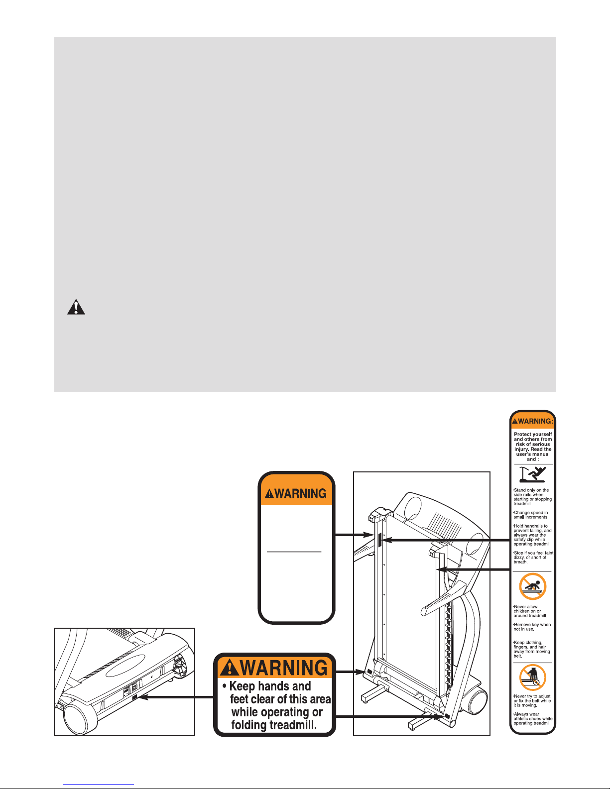
The decals shown below have been placed on your treadmill. If the decal is missing, or if it
is not legible, please call our Customer Service Department, toll-free, to order a free replacement decal (see ORDERING REPLACEMENT PARTS on the back cover of this manual). Apply the decal in the location shown. Note: The decal at the far right is shown at 50%
of actual size. The decal at the right is
shown at 80% of actual size.
4
Page 5
BEFORE YOU BEGIN
Thank you for selecting the new REEBOK®RX 820
treadmill. The RX 820 treadmill combines advanced
echnology with innovative design to help you get the
t
most from your exercise program in the convenience of
your home. And when youʼre not exercising, the unique
RX 820 can be folded up, requiring less than half the
floor space of other treadmills.
For your benefit, read this manual carefully before
using the treadmill. If you have questions after read-
ing this manual, please call our Customer Service
Water Bottle
Holder (Bottle
is not included)
Handrail
Lock Knob
Department toll-free at 1-800-999-3756, Monday
through Friday, 6 a.m. until 6 p.m. Mountain Time (ex-
luding holidays). To help us assist you, please note
c
the product model number and serial number before
calling. The model number of the treadmill is
RBTL69921. The serial number can be found on a
decal attached to the treadmill (see the front cover of
this manual for the location).
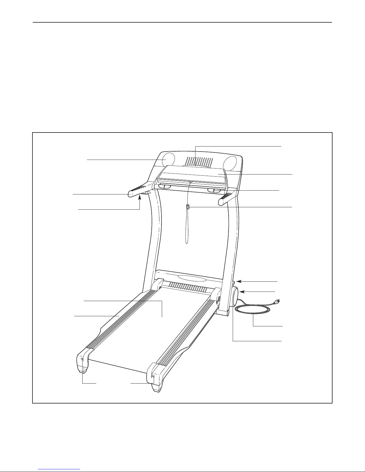
Before reading further, please review the drawing
below and familiarize yourself with the labeled parts.
Book Holder
Console
Pulse Sensor
Key/Clip
LEFT SIDE
Walking Belt
Foot Rail
RIGHT SIDE
On/Off Switch
Circuit Breaker
Power Cord
Front Wheel
Rear Roller
Adjustment Bolts
5
Page 6
ASSEMBLY
Assembly requires two people. Set the treadmill in a cleared area and remove the packing materials. Do not
ispose of the packing materials until assembly is completed. Assembly requires the included allen wrench
d
and your own 7/16” and 9/16” wrenches , rubber mallet , wire cutters ,
and Phillips screwdriver.
se the part chart attached in the center of this manual to identify small parts used in assembly. Each
U
bag of hardware is labeled with the corresponding assembly step.
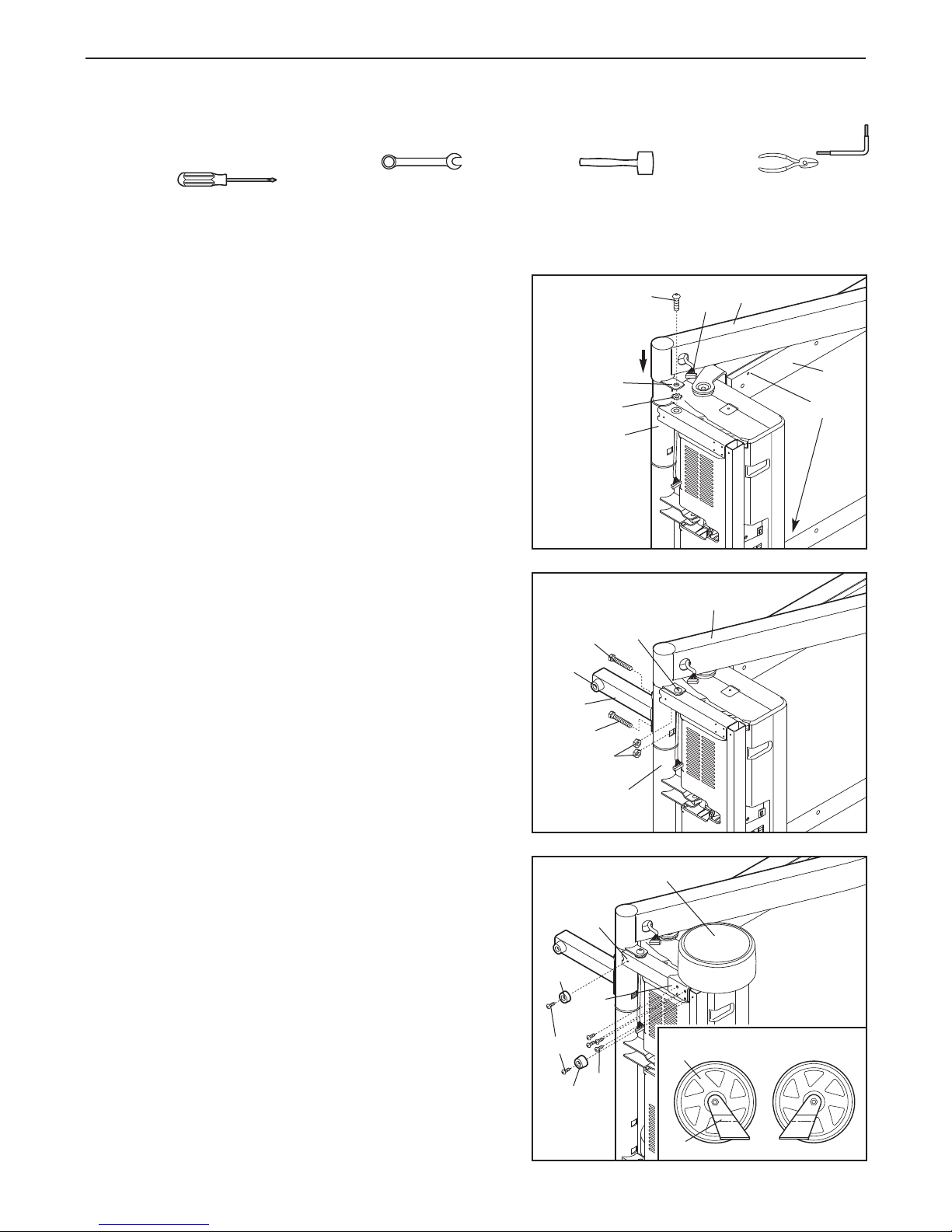
1. With the help of another person, carefully tip the treadmill
onto its left side. Have the other person continue to hold
the treadmill during steps 1 through 4. Note: Only half of
the hardware in the bags for steps 1 to 3 will be used. The
remaining hardware will be used at the end of step 4.
Identify the Right Upright (58), which contains the Wire
Harness (55). Insert the round tube on the Right Upright into
the Base (117) as shown. If necessary, apply grease to
the round tube and use a rubber mallet. Hold a Star Washer
(113) between the indicated tab and the Base, and Finger
tighten an Upright Bolt (66) through the tab into the Base.
Make sure that the two indicated Walking Platform
Screws (114) in the Walking Platform (100) are tight.
2. Attach a Base Leg (78) to the Base (117) with two Base
Leg Bolts (77) and two Base Leg Nuts (70). Make sure
that the Base Pad (75) is in the position shown. (Note:
The Base Leg Nuts fit into square holes in the Base. If
necessary, push or pull on the Right Upright [58] to align
the holes.) Do not fully tighten the Base Leg Bolts yet.
1
2
77
75
78
66
Tab
113
117
66
55
58
100
114
58
3. See the inset drawing. Identify the right Front Wheel (62)
by observing the direction that the Wheel Bracket (64)
slants.
Attach the Wheel Bracket (64) and the right Front Wheel
(62) to the Base (117) with four 3/4” Screws (12) as
shown.
Attach a Thin Base Pad (103) and a Thick Base Pad (75)
to the Base (117) with two 3/4” Screws (12) as shown.
6
3
103
12
75
77
117
64
12
70
117
62
62
64
Right
Left
Page 7
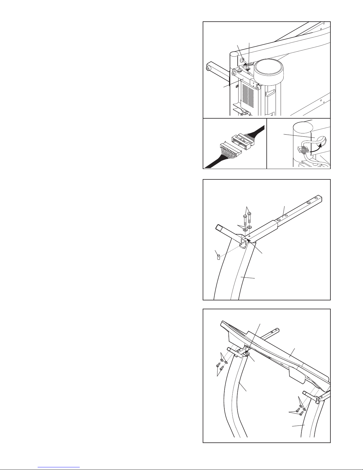
4. Locate the Belly Pan Wire Harness (124). Route the Belly
Pan Wire Harness over the Base (117) as shown.
Connect the Belly Pan Wire Harness to the Wire Harness
55). Be sure to insert the connectors properly (see
(
drawing 4a). IF THE CONNECTORS ARE NOT IN-
ERTED PROPERLY, THE CONSOLE MAY BE DAM-
S
AGED WHEN THE POWER IS TURNED ON. The connectors should slide together easily and snap into
place. If the connectors do not slide easily and snap into
place, turn a connector and try again.
See drawing 4b. Carefully wrap the wires around the connectors as shown. Insert the connectors and the excess
Wire Harness into the Right Upright (58).
With the help of another person, carefully tip the treadmill
onto its other side. Attach the Left Upright, the other Base
Leg, the left Front Wheel, and the other Base Pads (not
shown) as described in steps 1 through 3. (Note: There is
not a wire harness in the Left Upright.) Do not fully
tighten the bolts yet.
4
4a
117
55
124
4b
58
5. With the help of another person, carefully raise the
Uprights (35, 58) to the vertical position, with the wheels
and the walking platform on the floor as shown on page 5.
Have the other person hold a Handgrip Post (41) on the
Left Upright (35) as shown. Hold a Post Spacer (43) in-
side of the Handgrip Post. Insert a Post Bolt (44) with a
1/4” Washer (125) through the end hole in the Handgrip
Post and through the Post Spacer. Finger tighten the
Post Bolt. Finger tighten another Post Bolt (44) with a 1/4”
Washer (125) into the other hole. If necessary, tap the
Handgrip Post with a rubber mallet to make sure that it is
fully seated. Tighten the Post Bolt in the end hole.
Then, tighten the other Post Bolt.
Attach the other Handgrip Post (41) to the right Upright
(not shown) as described above.
6. Have another person hold the Console Base (52) near
the Uprights (35, 58). Locate the wire harness extending
from the Console Base. Connect the wire harness to the
Wire Harness (55) in the Right Upright. If the connectors
do not fit together easily, rotate them and then connect them. Carefully feed the connectors and the excess
wire harness into the Right Upright. Carefully set the
Console Base on the posts on the Uprights.
5
44
41
125
43
End
Hole
35
6
Wire Harness
113
52
55
Finger tighten four Console Bolts (42) with four Star
Washers (113) into the Uprights (35, 58) and the Console
Base (52). After all four Console Bolts have been started,
tighten them.
See step 1. Tighten the two Upright Bolts (66). See
step 2. Tighten the four Base Leg Bolts (77). Make
sure that the Base Leg Nuts (70) are fully seated in
the square holes. Note: It may be helpful to tip the
treadmill onto its side to tighten the Base Leg Bolts.
42
58
113
42
35
7
Page 8
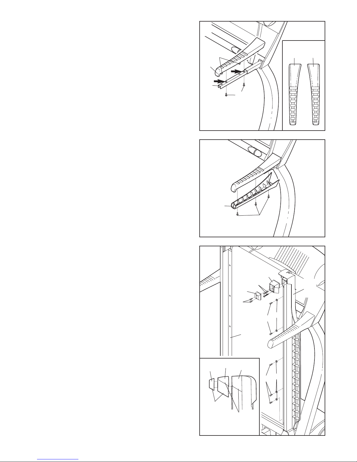
7. See the inset drawing. Identify the Right Top Handgrip
53); there are identifying marks inside the Handgrips.
(
Set the Right Top Handgrip on the right Handgrip Post
(41). Insert two 1/2” Screws (51) into the two holes in
the Handgrip Post indicated by the arrows. Tighten
the Screws into the Right Top Handgrip.
mportant: Be careful not to insert the two 1/2”
I
Screws (51) into the wrong holes in the Handgrip
Post (41), or tighten the Screws into the plastic
bosses on the bottom of the Right Top Handgrip (53).
7
B
53
41
osses
51
Left
21
Right
53
8. Attach the matching Right Bottom Handgrip (54) with
three 1/2” Screws (51).
Attach the Left Top Handgrip (21) and the Left Bottom
Handgrip (not shown) as described above.
9. Set the Right Foot Rail (98) and the Left Foot Rail (not
shown) on the sides of the Walking Platform (100). While
a second person holds the Foot Rails, raise the Walking
Platform to the position shown. Attach the Right Foot Rail
with five Foot Rail Screws (97) and five Foot Rail
Washers (96).
Attach the Left Foot Rail (not shown) in the same way.
Identify the Right Foot Housing (106) and one of the
Rubber Feet (104). See the inset drawing. Hold the Right
Foot Housing and the Rubber Foot near the upper end of
the Right Foot Rail (98) as shown. The ridge on the Right
Foot Housing should match the ridge on the Right Foot
Rail. In addition, the angle of the Rubber Foot should
match the angle of the Right Foot Housing. Make sure
that the parts are oriented exactly as shown. Attach the
Right Foot Housing with two Foot Housing Screws (105).
Attach the Rubber Foot with two Foot Screws (65).
Attach the Left Foot Housing (not shown) and the other
Rubber Foot (not shown) as described above.
Lower the Walking Platform (100) to the floor.
8
54
9
106
104
Matching
Angles
104
65
100
98
Ridges
105
51
106
97
97
98
96
96
Side View
8
Page 9
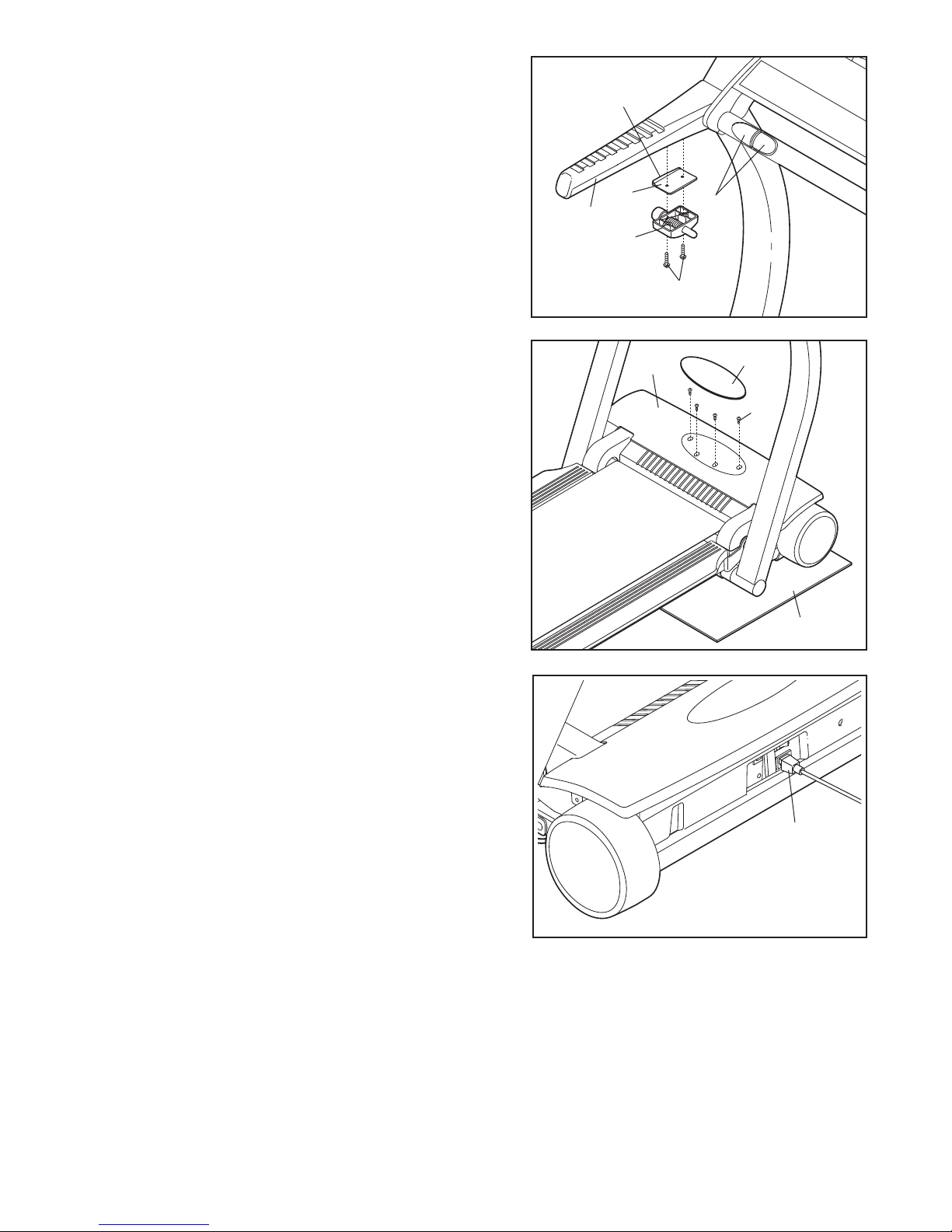
10.Attach the Latch Assembly (37) and the Latch Spacer
(39) to the Left Bottom Handgrip (40) with two Latch
Screws (36). Firmly tighten the Latch Screws. Note: The
idge on the Latch Spacer must be on the side shown.
r
f there are plastic ties around the left and right Pulse
I
Sensor Plates (2), cut off the plastic ties.
10
40
R
idge
9
3
37
2
36
11. Attach the Hood Cover (3) to the treadmill with four 1/2”
Screws (51). Firmly tighten the Screws.
Peel the backing off the Hood Decal (1). Position the
Hood Decal over the recess in the Hood Cover (3).
Press the Hood Decal into place.
Note: If the treadmill rocks slightly, tip the treadmill back
onto its side. See step 2. Loosen the four Base Leg Bolts
(77), adjust the positions of the Base Legs (78), and then
retighten the Base Leg Bolts. Raise the treadmill back to
the vertical position. Repeat until the rocking motion is
eliminated.
To protect the floor or carpet from damage, place the included Mat (129) under the front of the treadmill.
12. Plug the Power Cord (93) into the front of the treadmill as
shown.
Note: Extra parts may be included.
11
12
3
1
51
129
13. Make sure that all parts are properly tightened before you use the treadmill. Keep the included allen
wrench in a secure place. The allen wrench is used to adjust the walking belt (see pages 25 and 26). To protect the floor or carpet from damage, place a mat under the treadmill.
Note: The underside of the treadmill walking belt is coated with high-performance lubricant. During shipping,
a small amount of lubricant may be transferred to the top of the walking belt or the shipping carton. This is a
normal condition and does not affect treadmill performance. If there is lubricant on top of the walking belt,
simply wipe off the lubricant with a soft cloth and a mild, non-abrasive cleaner.
93
9
Page 10
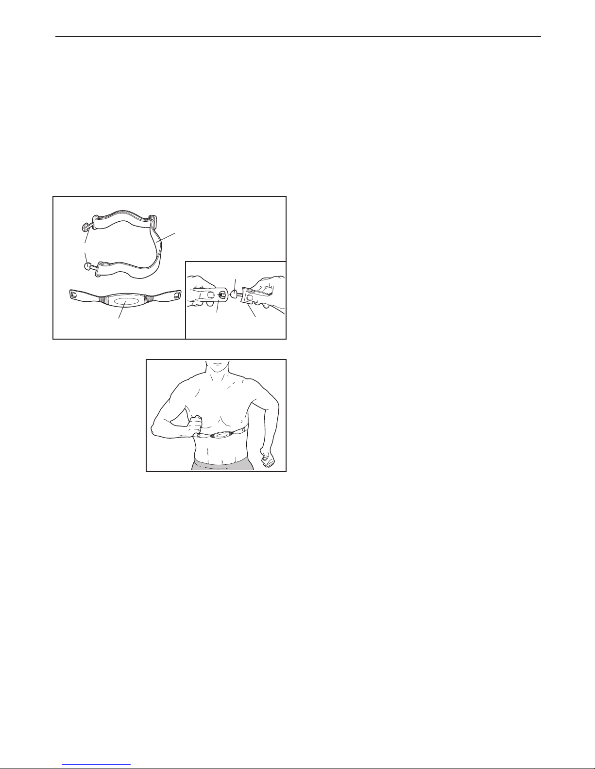
HOW TO USE THE CHEST PULSE SENSOR
OW TO PUT ON THE CHEST PULSE SENSOR
H
The chest pulse sensor consists of two components:
the chest strap and the sensor unit (see the drawing
elow). Insert the tab on one end of the chest strap into
b
one end of the sensor unit, as shown in the inset drawing. Press the end of the sensor unit under the buckle
on the chest strap. The tab should be flush with the
front of the sensor unit.
ried. If the chest pulse sensor is not dried after
d
each use, it may remain activated longer than necessary, draining the battery prematurely.
Store the chest pulse sensor in a warm, dry place.
•
Do not store the chest pulse sensor in a plastic bag
or other container that may trap moisture.
• Do not expose the chest pulse sensor to direct
sunlight for extended periods of time; do not expose
it to temperatures above 122° Fahrenheit (50°
Celsius) or below 14° Fahrenheit (-10° Celsius).
Chest Strap
Tabs
Tab
Sensor Unit
Next, wrap the
chest pulse sensor around your
chest and attach
the other end of
the chest strap to
the sensor unit.
Adjust the length
of the chest strap,
if necessary. The
chest pulse sensor should be under your clothes, tight against your
skin, and as high under the pectoral muscles or
breasts as is comfortable. Make sure that the logo on
the sensor unit is facing forward and is right-side-up.
Pull the sensor unit away from your body a few inches
and locate the two electrode areas on the inner side
(the electrode areas are covered by shallow ridges).
Using saline solution such as saliva or contact lens solution, wet both electrode areas. Return the sensor unit
to a position against your chest.
Sensor
Unit
Buckle
• Do not excessively bend or stretch the sensor unit
when using or storing the chest pulse sensor.
• Clean the sensor unit using a damp cloth—never
use alcohol, abrasives, or chemicals. The chest
strap may be hand washed and air dried.
CHEST PULSE SENSOR TROUBLESHOOTING
The instructions on the following pages explain
how the chest pulse sensor is used with the console. If the chest pulse sensor does not function
properly, try the steps below.
• Make sure that you are wearing the chest pulse sensor as described at the left. Note: If the chest pulse
sensor does not function when positioned as described, move it slightly lower or higher.
• Use saline solution such as saliva or contact lens
solution to wet the two electrode areas on the
sensor unit. If heart rate readings do not appear until
you begin perspiring, re-wet the electrode areas.
• As you walk or run on the treadmill, position yourself near the center of the walking belt. For the
console to display heart rate readings, the user
must be within armʼs length of the console.
• The chest pulse sensor is designed to work with
people who have normal heart rhythms. Heart rate
reading problems may be caused by medical
conditions such as premature ventricular contractions (pvcs), tachycardia bursts, and arrhythmia.
CHEST PULSE SENSOR CARE AND MAINTENANCE
• Thoroughly dry the chest pulse sensor after each
use. The chest pulse sensor is activated when the
electrode areas are wetted and the heart rate
monitor is put on; the chest pulse sensor shuts off
when it is removed and the electrode areas are
• The operation of the chest pulse sensor can be
affected by magnetic interference caused by high
power lines or other sources. If it is suspected that
this is a problem, try relocating the treadmill.
• The CR2032 battery may need to be replaced (see
page 26).
10
Page 11
OPERATION AND ADJUSTMENT
THE PERFORMANT LUBETMWALKING BELT
our treadmill features a walking belt coated with
Y
PERFORMANT LUBE
IMPORTANT: Never apply silicone spray or other
substances to the walking belt or the walking platform. Such substances will deteriorate the walking
belt and cause excessive wear.
HOW TO PLUG IN THE POWER CORD
TM
, a high-performance lubricant.
DANGER: Improper connection
of the equipment-grounding conductor can
result in an increased risk of electric shock.
Check with a qualified electrician or serviceman if you are in doubt as to whether the
product is properly grounded. Do not modify
the plug provided with the product—if it will
not fit the outlet, have a proper outlet
installed by a qualified electrician.
Your treadmill, like any other type of sophisticated
electronic equipment, can be seriously damaged by
sudden voltage changes in your homeʼs power.
Voltage surges, spikes, and noise interference can
result from weather conditions or from other appliances being turned on or off. To decrease the possi-
bility of your treadmill being damaged, always use
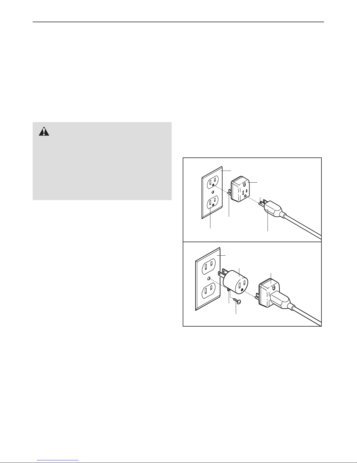
a surge suppressor with your treadmill (see drawing 1 at the right). To purchase a surge suppressor, see your local REEBOK dealer or call 1-800806-3651 and order part number 146148.
an equipment-grounding conductor and a grounding
plug. Plug the power cord into a surge suppressor,
nd plug the surge suppressor into an appropriate
a
outlet that is properly installed and grounded in
accordance with all local codes and ordinances.
Important: The treadmill is not compatible with
GFCI-equipped outlets.
This product is for use on a nominal 120-volt circuit,
and has a grounding plug that looks like the plug illustrated in drawing 1 below. A temporary adapter that
looks like the adapter illustrated in drawing 2 may be
used to connect the surge suppressor to a 2-pole
receptacle as shown in drawing 2 if a properly
grounded outlet is not available.
1
Grounded Outlet Box
Surge Suppressor
Grounding Pin
Grounding Pin
Grounded Outlet
2
Grounded Outlet Box
Adapter
Grounding Plug
Surge Suppressor
Use only a single-outlet surge suppressor that is
UL 1449 listed as a transient voltage surge suppressor (TVSS). The surge suppressor must have a
UL suppressed voltage rating of 400 volts or less
and a minimum surge dissipation of 450 joules.
The surge suppressor must be electrically rated
for 120 volts AC and 15 amps. There must be a
monitoring light on the surge suppressor to indicate whether it is functioning properly. Failure to
use a properly functioning surge suppressor could
result in damage to the control system of the
treadmill. If the control system is damaged, the
walking belt may change speed or stop unexpectedly, which may result in a fall and serious injury.
This product must be grounded. If it should malfunc-
tion or break down, grounding provides a path of least
resistance for electric current to reduce the risk of electric shock. This product is equipped with a cord having
Lug
Metal Screw
The temporary adapter should be used only until a
properly grounded outlet (drawing 1) can be installed
by a qualified electrician.
The green-colored rigid ear, lug, or the like extending
from the adapter must be connected to a permanent
ground such as a properly grounded outlet box cover.
Whenever the adapter is used it must be held in place
by a metal screw. Some 2-pole receptacle outlet box
covers are not grounded. Contact a qualified electrician to determine if the outlet box cover is
grounded before using an adapter.
11
Page 12
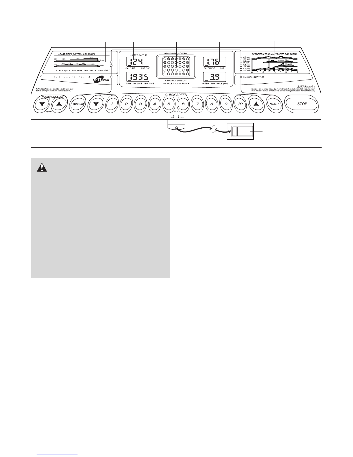
CONSOLE DIAGRAM
Manual/Program Indicators
Note: If there is a thin sheet of plastic
on the face of the console, remove it.
Display
CAUTION: Before operating the
console, read the following precautions.
• Do not stand on the walking belt when turning on the power.
• Always wear the clip (see the drawing
above) while operating the treadmill.
•Adjust the speed in small increments to
avoid sudden jumps in speed.
Program Display
Key
Display
The console also features new iFIT.com interactive
technology. IFIT.com technology is like having a personal trainer right in your home. Using the included
audio cable, you can connect the treadmill to your
home stereo, portable stereo, or computer and play
special iFIT.com CD programs (one free iFIT.com CD is
included; others are available separately). IFIT.com CD
programs automatically control the speed and incline of
the treadmill as a personal trainer guides you through
every step of your workout. High-energy music provides
added motivation. Each CD features two programs designed by certified personal trainers.
Program Profiles
Clip
•To reduce the possibility of electric shock,
keep the console dry. Avoid spilling liquids
on the console and place only a sealed water
bottle in the water bottle holder.
FEATURES OF THE CONSOLE
The advanced console offers an impressive array of
features to help you get the most from your exercise.
When the manual mode of the console is selected, the
speed and incline of the treadmill can be changed with
a touch of a button. As you exercise, the console will
display continuous exercise feedback. You can even
measure your heart rate using the built-in handgrip
pulse sensor or the chest pulse sensor.
Four certified personal trainer programs are also
offered. Each program automatically controls the
speed and incline of the treadmill to give you an effective workout. Two heart rate programs are also featured. Each program controls the speed and incline of
the treadmill to keep your heart rate near a target level
during your workouts.
In addition, you can connect the treadmill to your VCR
and TV and play iFIT.com video programs (one free
iFIT.com videocassette is included; others videocassettes are available separately). Video programs offer
the same benefits as iFIT.com CD programs, but add
the excitement of working out with a class and an
instructor—the hottest new trend at health clubs.
With the treadmill connected to your computer, you
can also go to our Web site at www.iFIT.com and access basic programs, audio programs, and video programs directly from the internet. Additional options are
soon to be available. See www.iFIT.com for details.
To purchase iFIT.com CDʼs or videocassettes, call
toll-free 1-800-735-0768.
To use the manual mode of the console, follow the
steps beginning on page 13. To use a personal trainer
program, see page 15. To use a heart rate program,
see page 16. To use an iFIT.com CD or video program, see page 20. To use an iFIT.com program di-
rectly from our Web site, see page 22.
12
Page 13
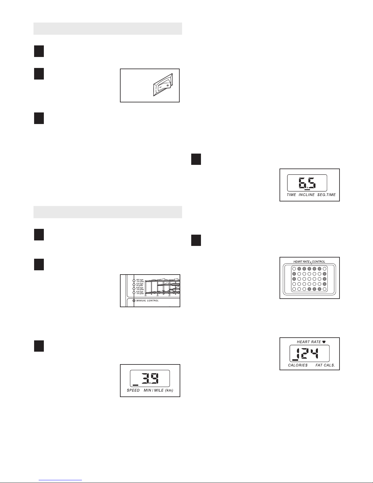
OW TO TURN ON THE POWER
H
Plug in the power cord (see page 11).
1
Locate the on/off
2
witch near the power
s
cord. Move the on/off
switch to the on position.
Stand on the foot rails of the treadmill. Find the clip
3
attached to the key (see the drawing on page 12)
and slide the clip onto the waistband of your
clothes. Next, insert the key into the console. After
a moment, the displays and various indicators will
light. Test the clip by carefully taking a few
steps backward until the key is pulled from the
console. If the key is not pulled from the console, adjust the position of the clip.
HOW TO USE THE MANUAL MODE
Insert the key fully into the console.
On
osition
P
1
See HOW TO TURN ON THE POWER above.
Each time a button is pressed, the speed setting
will change by 0.1 mph; if a button is held down,
the speed setting will change in increments of 0.5
ph. To change the speed setting quickly, press
m
the Quick Speed buttons. Note: The console can
isplay speed and distance in either miles or
d
kilometers. For simplicity, all instructions in
this section refer to miles.
To stop the walking belt, press the Stop button.
The Time/Incline/Segment Time display will begin
to flash. To restart the walking belt, press the Start
s
s
button or the Speed
Note: During the first few minutes that the treadmill
is used, inspect the alignment of the walking belt
and align it if necessary (see page 26).
Change the incline of the treadmill as desired.
button.
4
To change the incline of
the treadmill, press the
Incline buttons. Each time
a button is pressed, the
incline will change by
0.5%. Note: After the buttons are pressed, it may take a moment for the
treadmill to reach the selected incline setting.
Follow your progress with the LED track and
5
the displays.
Select the manual mode.
2
When the key is inserted, the manual
mode will be selected
and the Manual Control
indicator will light. If a
program has been
selected, press the Program button repeatedly to
reselect the manual mode.
Press the Start button or the Speed
3
start the walking belt.
A moment after the button is pressed, the
walking belt will begin to
move at 1 mph. Hold
the handrails and begin
walking. As you exercise, change the speed of the walking belt as de-
sired by pressing the Speed
t
t
and
ss
buttons.
s
s
button to
The LED Track—When
the manual mode or the
iFIT.com mode is selected, the program display will show an LED
track representing 1/4
mile. As you exercise,
the indicators around the track will light in sequence
until you have completed 1/4 mile. A new lap will
then begin.
Calories/Fat Calories/
Heart Rate display—
This display shows the
approximate numbers of
calories and fat calories
you have burned (see
FAT BURNING on page 27). The display will
change from one number to the other every few
seconds, as shown by the indicators in the display. The display will also show your heart rate
when you use the handgrip pulse sensor (see
step 6 on page 14) or the chest pulse sensor (see
page 10).
13
Page 14
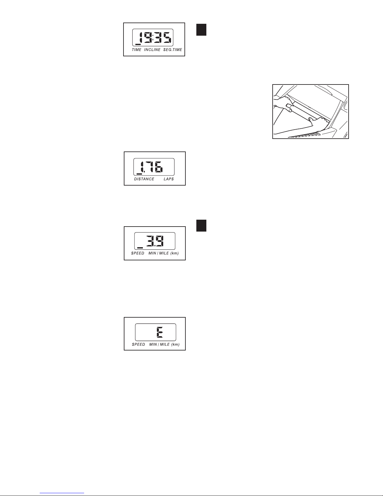
Time/Incline/Segment
Time display—When
the manual mode or the
FIT.com mode is se-
i
lected, this display will
how the elapsed time
s
and the incline level of the treadmill. The display
will change from one number to the other every
few seconds, as shown by the indicators in the
display. When a personal trainer program or a
heart rate program is selected, the display will
show the time remaining in the program, the time
remaining in the current segment of the program,
and the incline level. Note: Each time the incline
changes, the display will show the current incline
setting for several seconds.
Distance/Laps
display—This display
shows the distance that
you have walked and the
number of 1/4-mile laps
you have completed.
The display will change from one number to the
other every few seconds, as shown by the indicators in the display.
Speed/Min-Mile
display—This display
shows the speed of the
walking belt and your
current pace (pace is
measured in minutes per
mile). The display will change from one number to
the other every few seconds, as shown by the indicators in the display. Note: Each time the speed
changes, the display will show the current speed
setting for several seconds.
Note: The console can
display speed and distance in either miles or
kilometers. To find which
unit of measurement is
selected, hold down the
Stop button while inserting the key into the console. An “E” for English miles or an “M” for metric
kilometers will appear in the display. Press the
ss
Speed
ment. When the desired unit of measurement is
selected, remove the key and then reinsert it.
button to change the unit of measure-
easure your heart rate, if desired.
M
6
To measure your heart rate, use the chest pulse
sensor (see page 10) or the handgrip pulse sen-
or (follow the instructions below). Note: Before
s
using the handgrip pulse sensor, make sure that
your hands are clean.
To measure your
heart rate, stand
on the foot rails
and place your
hands on the
metal contacts on
the handrail. Your
palms must be
resting on the contacts—avoid moving your hands. When your
pulse is detected, the heart-shaped indicator in the
Calories/Fat Calories/Heart Rate display will flash,
and then your heart rate will be shown. For the
most accurate heart rate reading, continue to
hold the contacts for about 15 seconds. The
chest pulse sensor (see page 10) can also be
used.
When you are finished exercising, remove the
7
key.
Step onto the foot rails, press the Stop button, and
adjust the incline of the treadmill to the lowest
setting. The incline must be at the lowest setting
when the treadmill is folded to the storage position or the treadmill will be damaged. Next, re-
move the key from the console and put it in a secure place. Note: If the displays and various indi-
cators on the console remain lit after the key is
removed, the console is in the “demo” mode.
See page 23 and turn off the demo mode.
When you are finished using the treadmill, move
the on/off switch near the power cord to the off
position and unplug the power cord.
To reset the displays, press the Stop button, remove the key, and then reinsert the key.
14
Page 15
OW TO USE PERSONAL TRAINER PROGRAMS
H
Insert the key fully into the console.
1
See HOW TO TURN ON THE POWER on page
3.
1
Select one of the personal trainer programs.
2
When the key
is inserted, the
manual mode
will be selected. To select one of the
personal
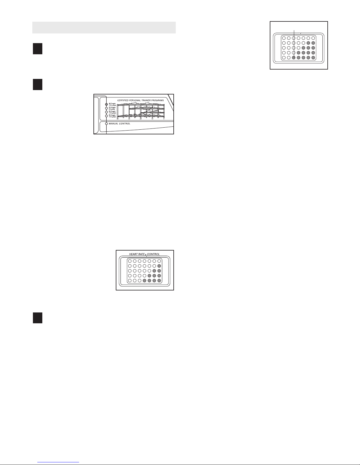
trainer programs, press the Program button repeatedly until one of the four personal trainer program indicators lights. When a personal trainer
program is selected, the Time/Incline/Segment
Time display will flash the maximum incline setting
for the program for six seconds, and the
Speed/Min-mile display will flash the maximum
speed setting.
speed setting for the
first segment will be
shown in the flashing
urrent Segment col-
C
umn of the program dis-
lay. (The incline set-
p
tings are not shown in
the program display.)
The speed settings for the next four segments will
be shown in the four columns to the right.
When only three seconds remain in the first segment of the program, both the Current Segment
column and the column to the right will flash and a
tone will sound. In addition, if the speed and/or
incline of the treadmill is about to change, the
Speed/Min-mile display and/or the Time/Incline/
Segment Time display will flash to alert you, and
three tones will sound. When the first segment is
completed, all speed settings will move one col-
umn to the left. The speed setting for the second
segment will then be shown in the flashing
Current Segment column and the treadmill will automatically adjust to the speed and incline settings
for the second segment.
Current Segment
The four profiles on the right side of the console
show how the speed and incline of the treadmill
will change during the programs. The numbers
beside the profiles show the maximum speed and
incline settings for the programs.
The program display
will show the first
speed settings for the
program. The Time/
Incline/Segment Time
display will show how
long the program will
last.
Press the Start button or the Speed
3
start the program.
A moment after the button is pressed, the treadmill will automatically adjust to the first speed and
incline settings for the program. Hold the handrails
and begin walking.
Each program is divided into several time segments of different lengths. The Time/Incline/
Segment Time display will show both the time remaining in the program and the time remaining in
the current segment. One speed setting and one
incline setting are programmed for each segment.
(The same speed setting and/or incline setting may
be programmed for consecutive segments.) The
button to
ss
The program will continue in this way until the
speed setting for the last segment is shown in the
Current Segment column and no time remains in
the Time/Incline/Segment Time display. The walking belt will then slow to a stop.
Note: Each time a segment ends and the speed
settings move one column to the left, if all of the
indicators in the Current Segment column are lit,
the speed settings will move downward so that only
the highest indicators in the columns will appear in
the program display. When the speed settings
move to the left again and not all of the indicators
in the Current Segment column are lit, the speed
settings will move back up.
If the speed or incline setting for the current
segment is too high or too low, you can manually
override the setting by pressing the Speed or
Incline buttons. Every few times one of the Speed
buttons is pressed, an additional indicator will light
or darken in the Current Segment column. If any of
the columns to the right of the Current Segment
column have the same number of lit indicators as
the Current Segment column, an additional indicator may light or darken in those columns as well.
Important: When the current segment of the
program ends, the treadmill will automatically
adjust to the speed and incline settings for the
next segment.
15
Page 16
To stop the program temporarily, press the Stop
button. The Time/Incline/Segment Time display
will begin to flash. To restart the program, press
the Start button or the Speed
program, press the Stop button, remove the key,
and then reinsert the key.
Follow your progress with the displays.
button. To end the
s
s
4
See step 5 on page 13.
Measure your heart rate, if desired.
5
See step 6 on page 14.
When the program is completed, remove the
6
key from the console.
When the program has ended, make sure that
the incline of the treadmill is at the lowest setting. Next, remove the key from the console and
put it in a safe place.Note: If the displays and
various indicators on the console remain lit
after the key is removed, the console is in the
“demo” mode. See page 23 and turn off the
demo mode.
When you are finished using the treadmill, move
the on/off switch near the power cord to the off
position and unplug the power cord.
OW TO USE HEART RATE PROGRAMS
H
CAUTION: I
lems, or if you are over 60 years of age and
have been inactive, do not use the heart rate
programs. If you are taking medication regularly, consult your physician to find whether the
medication will affect your exercise heart rate.
Follow the steps below to use the heart rate programs.
Note: You must wear the chest pulse sensor (see
page 10) to use the heart rate programs.
Put on the chest pulse sensor.
f you have heart prob-
1
See the instructions on page 10.
Insert the key fully into the console.
2
See HOW TO TURN ON THE POWER on page
13.
Select a heart rate program.
3
When the key is
inserted, the
manual mode
will be selected.
To select one of
the heart rate
programs,
press the Program button repeatedly until one of
the two heart rate program indicators lights.
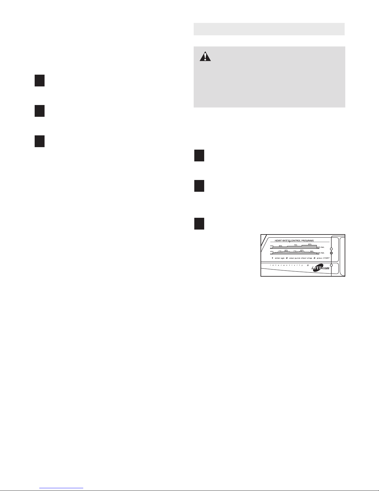
The two profiles on the left side of the console
show how the target heart rate will change during
the programs. The numbers above the profiles
represent percentages of your estimated maxi-
mum heart rate. (Your estimated maximum heart
rate is determined by subtracting your age from
220. For example, if you are 30 years old, your
estimated maximum heart rate is 190 beats per
minute [220 – 30 = 190]. If you are 30 years old, a
target heart rate setting of 50% is equal to 95
beats per minute [50% of 190 is 95]).
16
Page 17
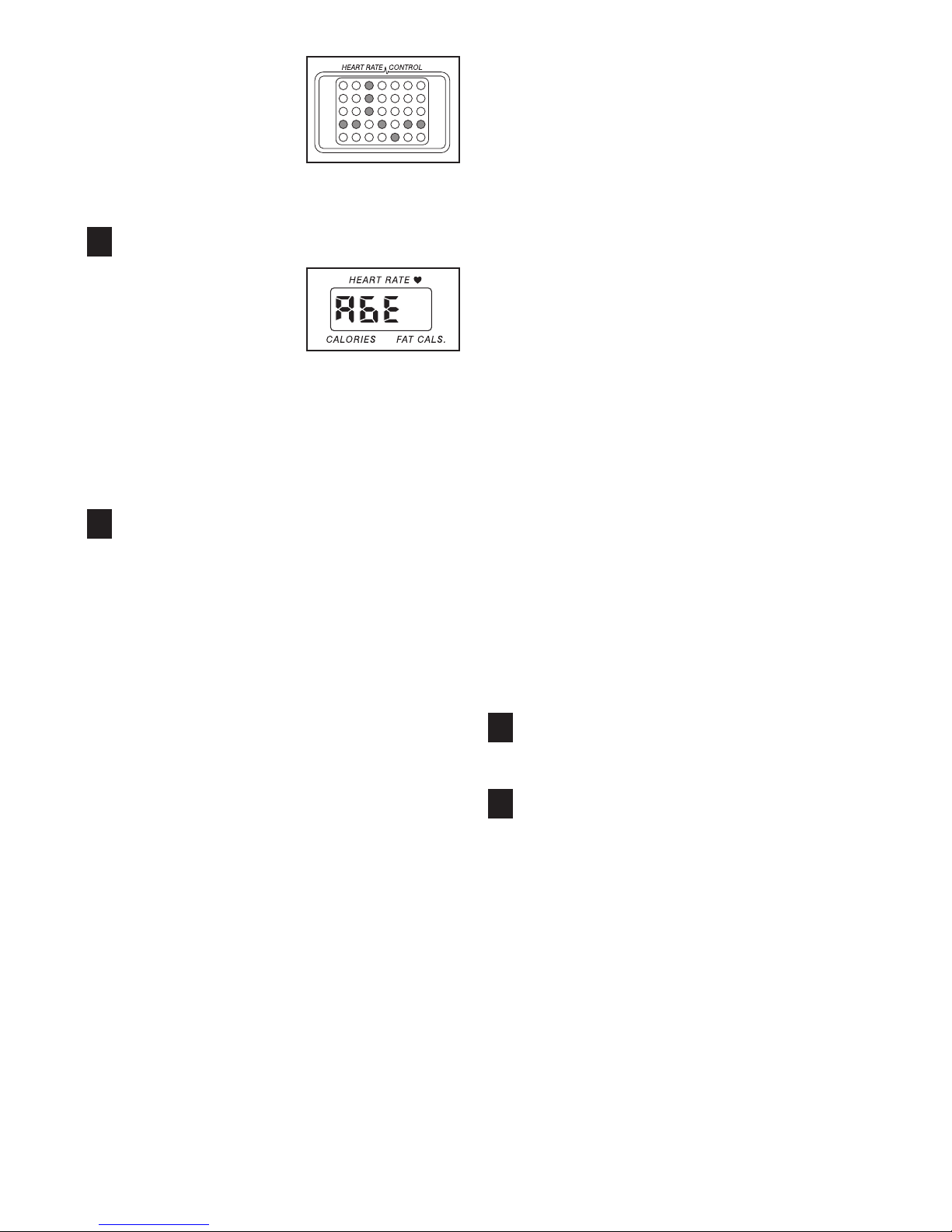
During heart rate programs, the program
display will show a
raphic that represents
g
your heart rate. Each
ime a heartbeat is de-
t
tected, an additional
peak will appear.
Enter your age.
4
When a heart rate program is selected, the letters AGE and the current
age setting will begin to
flash in the Calories/
Fat Calories/Heart Rate
display. You must enter your age to use a heart
rate program. If you have already entered your
age, go to step 5. If you have not entered your
age, press the Incline (Age Set) buttons until your
age is shown. Your age will then be saved in memory.
Press the Start button or the Speed
5
start the program.
A moment after the button is pressed, the treadmill will automatically adjust to the first speed and
incline settings for the program. Hold the handrails
and begin walking.
Each heart rate program is divided into one-minute
segments. The Time/Incline/Segment Time display
will show both the time remaining in the program
and the time remaining in the current segment of
the program. One target heart rate setting is programmed for each segment. (The same target
heart rate setting may be programmed for consecutive segments.)
When only three seconds remain in the first oneminute segment of the program, a series of tones
will sound and the Time/Incline/Segment Time
display and the Speed/Min-Mile display will flash.
ss
button to
The speed and/or incline of the treadmill will then
change, if needed, to bring your heart rate closer to
the target heart rate setting for the next segment.
he program will continue until no time remains in
T
the program. The walking belt will then slow to a
top.
s
If the speed or incline setting for the current segment is too high or too low, you can adjust the setting with the Speed or Incline buttons. However, if
you decrease the speed, the incline will automatically increase; if you increase the speed, the incline will decrease. If you increase the incline, the
speed will decrease; if you decrease the incline,
the speed will increase. The treadmill will always
attempt to keep your heart rate near the target
heart rate setting for the current segment. Note:
When the incline reaches the lowest setting, the
speed cannot be increased any further. When the
incline reaches the highest setting, the speed cannot be decreased any further.
If your pulse is not detected during the program,
the letters PLS will flash in the Calories/Fat
Calories/Heart Rate display and the speed and incline of the treadmill may automatically decrease
until your pulse is detected. If this occurs, see the
instructions on page 10.
To stop the program at any time, press the Stop
button. Heart rate programs should not be stopped
temporarily and then restarted. To use a heart rate
program again, reselect the program and start it at
the beginning.
Follow your progress with the displays.
6
See step 5 on page 13.
When the program is completed, remove the
7
key from the console.
See step 6 on page 16.
17
Page 18
HOW TO CONNECT THE TREADMILL TO YOUR
LINE OUT
P
HONES
LINE OUT
PHONES
AUDIO OUT
RIGHT
L
EFT
A
LINE OUT
AUDIO OUT
RIGHT
LEFT
A
PHONES
LINE OUT
B
A
UDIO OUT
RIGHT
LEFT
A
LINE OUT
PHONES
LINE OUT
PHONES
PHONES
PHONES
D PLAYER, VCR, OR COMPUTER
C
To use iFIT.com CDʼs, the treadmill must be con-
nected to your portable CD player, portable stereo,
home stereo, or computer with CD player. See pages
8 and 19 for connecting instructions. To use iFIT.com
1
videocassettes, the treadmill must be connected to
your VCR. See page 20 for connecting instructions. To
use iFIT.com programs directly from our internet
site, the treadmill must be connected to your home
computer. See page 19 for connecting instructions.
HOW TO CONNECT YOUR PORTABLE CD PLAYER
Note: If your CD player has separate LINE OUT and
PHONES jacks, see instruction A below. If your CD
player has only one jack, see instruction B.
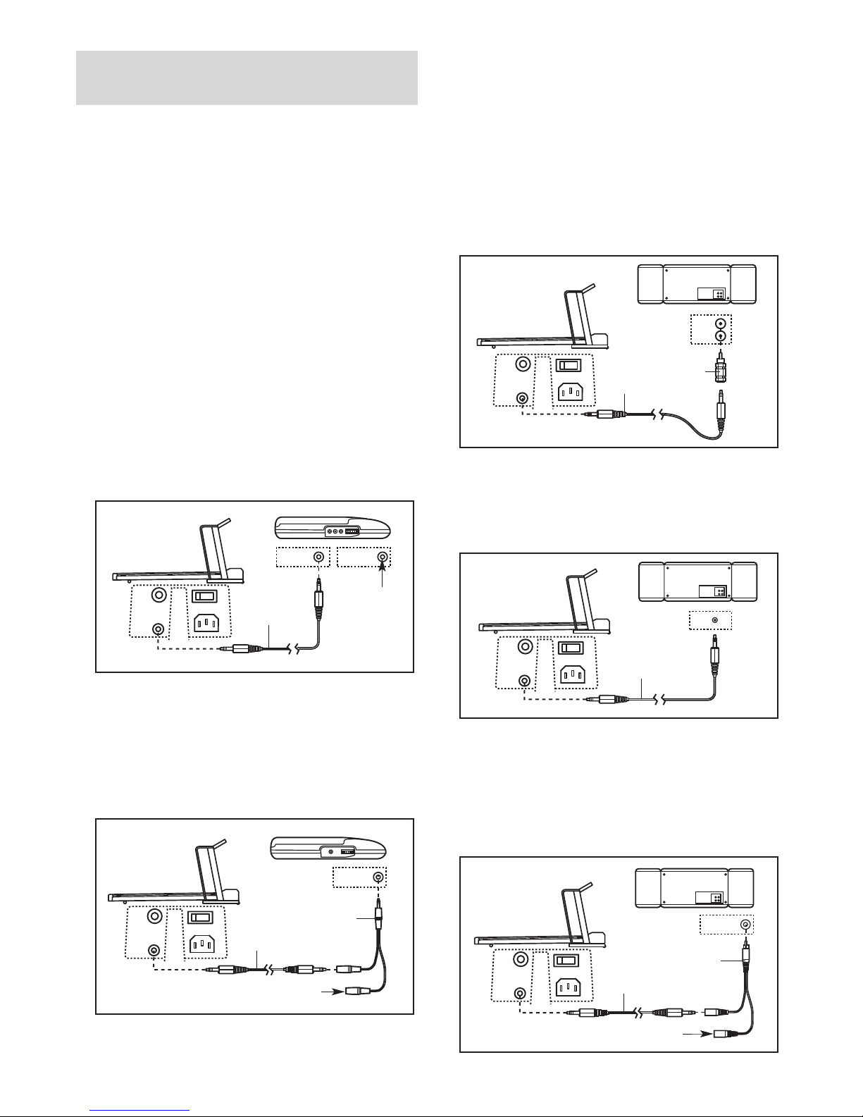
A. Plug one end of the audio cable into the jack on the
front of the treadmill near the power cord. Plug the
other end of the cable into the LINE OUT jack on
your CD player. Plug your headphones into the
PHONES jack.
A
HOW TO CONNECT YOUR PORTABLE STEREO
Note: If your stereo has an RCA-type AUDIO OUT
ack, see instruction A below. If your stereo has a
j
3.5mm LINE OUT jack, see instruction B. If your
tereo has only a PHONES jack, see instruction C.
s
A. Plug one end of the audio cable into the jack on the
front of the treadmill near the power cord. Plug the
other end of the cable into the included adapter. Plug
the adapter into an AUDIO OUT jack on your stereo.
A
Audio
Adapter
Cable
B. Plug one end of the audio cable into the jack on the
front of the treadmill near the power cord. Plug the
other end of the cable into the LINE OUT jack on
your stereo.
B. Plug one end of the audio cable into the jack on the
front of the treadmill near the power cord. Plug the
other end of the cable into a 3.5mm Y-adapter (available at electronics stores). Plug the Y-adapter into
Audio
Cable
Head-
phones
the PHONES jack on your CD player. Plug your
headphones into the other side of the Y-adapter.
B
Audio
Cable
Headphones
3.5mm
Y-adapter
B
Audio
Cable
C. Plug one end of the audio cable into the jack on the
front of the treadmill near the power cord. Plug the
other end of the cable into a 3.5mm Y-adapter
(available at electronics stores). Plug the Y-adapter
into the PHONES jack on your stereo. Plug your
headphones into the other side of the Y-adapter.
C
3.5mm
Audio
Y-adapter
Cable
Headphones
18
Page 19
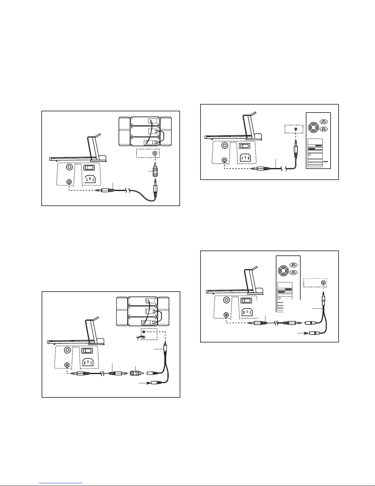
HOW TO CONNECT YOUR HOME STEREO
L
INE OUT
C
D
V
CR
Amp
LINE OUT
LINE OUT
A
LINE OUT
CD
VCR
Amp
LINE OUT
CD
VCR
Amp
LINE OUT
A
PHONES
LINE OUT
HOW TO CONNECT YOUR COMPUTER
Note: If your stereo has an unused LINE OUT jack,
ee instruction A below. If the LINE OUT jack is
s
being used, see instruction B.
A. Plug one end of the audio cable into the jack on the
front of the treadmill near the power cord. Plug the
other end of the cable into the included adapter.
Plug the adapter into the LINE OUT jack on your
stereo.
A
Audio
Adapter
Cable
B. Plug one end of the audio cable into the jack on the
front of the treadmill near the power cord. Plug the
other end of the cable into the included adapter.
Plug the adapter into an RCA Y-adapter (available
at electronics stores). Next, remove the wire that is
currently plugged into the LINE OUT jack on your
stereo and plug the wire into the unused side of the
Y-adapter. Plug the Y-adapter into the LINE OUT
jack on your stereo.
Note: If your computer has a 3.5mm LINE OUT jack,
ee instruction A. If your computer has only a
s
PHONES jack, see instruction B.
A. Plug one end of the audio cable into the jack on the
front of the treadmill near the power cord. Plug the
other end of the cable into the LINE OUT jack on
your computer.
A
Audio
Cable
B. Plug one end of the audio cable into the jack on the
front of the treadmill near the power cord. Plug the
other end of the cable into a 3.5mm Y-adapter
(available at electronics stores). Plug the Y-adapter
into the PHONES jack on your computer. Plug your
headphones or speakers into the other side of the
Y-adapter.
B
B
Audio
Cable
3.5mm
Y-adapter
Headphones/Speakers
RCA
Audio
Cable
Y-adapter
Adapter
Wire removed from
LINE OUT jack
19
Page 20
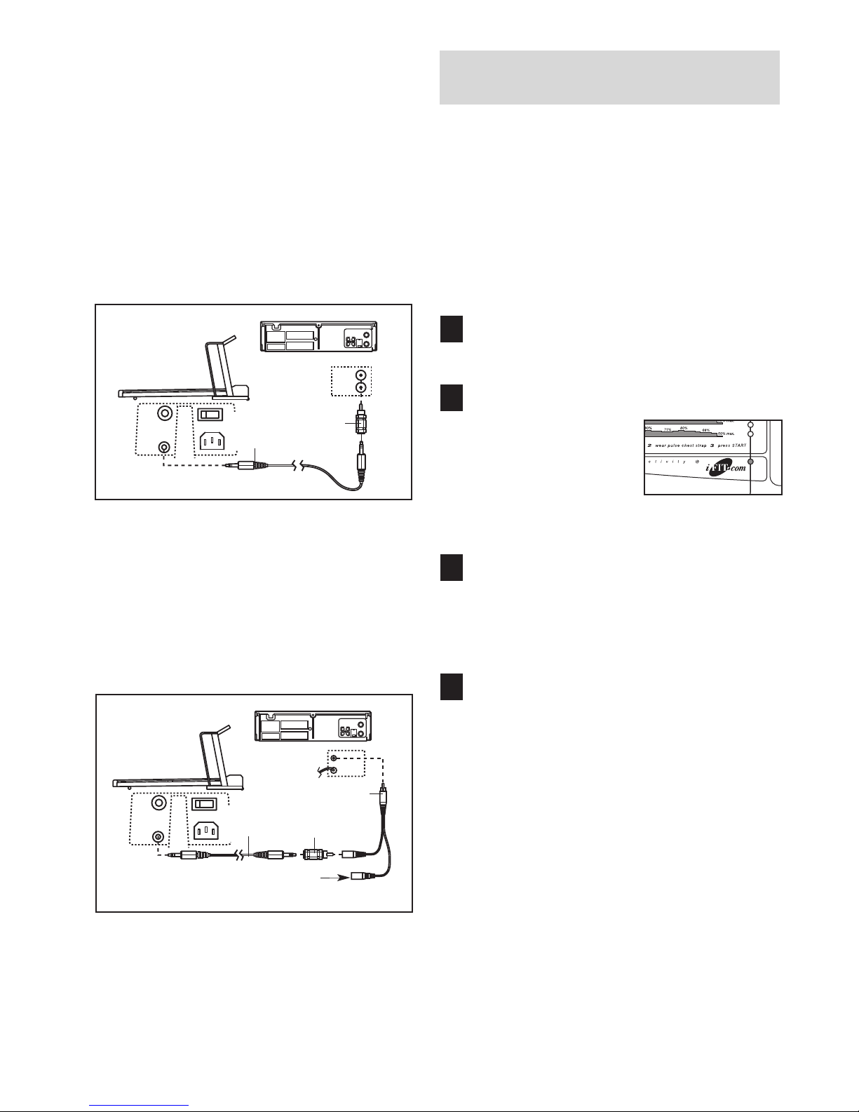
HOW TO CONNECT YOUR VCR
A
UDIO OUT
RIGHT
LEFT
VIDEO AUDIO
ANT. IN
RF OUT
IN
OUT
CH
34
A
A
UDIO OUT
RIGHT
LEFT
VIDEO AUDIO
ANT. IN
RF OUT
IN
O
UT
CH
34
VIDEO AUDIO
ANT. IN
RF OUT
IN
OUT
CH
34
Note: If your VCR has an unused AUDIO OUT jack,
ee instruction A below. If the AUDIO OUT jack is
s
being used, see instruction B. If you have a TV
ith a built-in VCR, see instruction B. If your VCR
w
is connected to your home stereo, see HOW TO
CONNECT YOUR HOME STEREO on page 19.
A. Plug one end of the audio cable into the jack on the
front of the treadmill near the power cord. Plug the
other end of the cable into the included adapter.
Plug the adapter into the AUDIO OUT jack on your
VCR.
HOW TO USE IFIT.COM CD AND VIDEO
ROGRAMS
P
To use iFIT.com CDʼs or videocassettes, the treadmill
must be connected to your portable CD player, portable
stereo, home stereo, computer with CD player, or
CR. See HOW TO CONNECT THE TREADMILL TO
V
YOUR CD PLAYER, VCR, OR COMPUTER on page
18. Note: To purchase iFIT.com CDʼs or videocas-
settes, call toll-free 1-800-735-0768.
Follow the steps below to use an iFIT.com CD or video
program.
A
Audio
Adapter
Cable
B. Plug one end of the audio cable into the jack on the
front of the treadmill near the power cord. Plug the
other end of the cable into the included adapter.
Plug the adapter into an RCA Y-adapter (available
at electronics stores). Next, remove the wire that is
currently plugged into the AUDIO OUT jack on your
VCR and plug the wire into the unused side of the
Y-adapter. Plug the Y-adapter into the AUDIO OUT
jack on your VCR.
B
RCA Y-adapter
Audio
Cable
Adapter
Insert the key into the console.
1
See HOW TO TURN ON THE POWER on page 13.
Select the iFIT.com mode.
2
When the key is inserted, the manual
mode will be selected.
To use iFIT.com CDʼs
or videocassettes,
press the Program button repeatedly until the iFIT.com indicator lights.
Insert the iFIT.com CD or videocassette.
3
If you are using an iFIT.com CD, insert the CD
into your CD player. If you are using an iFIT.com
videocassette, insert the videocassette into your
VCR.
Press the PLAY button on your CD player or
4
VCR.
A moment after the button is pressed, your personal trainer will begin guiding you through your
workout. Simply follow your personal trainerʼs
instructions. Note: If the Time/Incline/Segment
Time display is flashing, press the Start button or
s
the Speed
will not respond to a CD or video program when
the Time/Incline/Segment Time display is flashing.
s
button on the console. The treadmill
Wire removed from
AUDIO OUT jack
During the CD or video program, an electronic
“chirping” sound will alert you when the speed
and/or incline of the treadmill is about to change.
CAUTION: Always listen for the “chirp” and be
prepared for speed and/or incline changes. In
some instances, the speed and/or incline may
change before the personal trainer describes
the change.
20
Page 21

If the speed or incline settings are too high or too
low, you can manually override the settings at any
time by pressing the Speed or Incline buttons on
he console. However, when the next “chirp” is
t
heard, the speed and/or incline will change to
he next settings of the CD or video program.
t
To stop the walking belt at any time, press the
Stop button on the console. The Time/Incline/
Segment Time display will begin to flash. To
restart the program, press the Start button or the
Speed
will begin to move at 1 mph. When the next
“chirp” is heard, the speed and incline will
change to the next settings of the CD or video
program.
When the CD or video program is completed, the
walking belt will stop and the Time/Incline/Segment
Time display will begin to flash. Note: To use another CD or video program, press the Stop button
or remove the key and go to step 1 on page 20.
Note: If the speed or incline of the treadmill
does not change when a “chirp” is heard:
• Make sure that the iFIT.com indicator is lit and
that the Time/Incline/Segment Time display is
not flashing. If the Time/Incline/Segment Time
display is flashing, press the Start button or
the Speed
button. After a moment, the walking belt
s
s
button on the console.
s
s
• Adjust the volume of your CD player or VCR.
If the volume is too high or too low, the console may not detect the program signals.
• Make sure that the audio cable is properly
connected, that it is fully plugged in, and that
it is not wrapped around a power cord.
• If you are using your portable CD player and
the CD skips, set the CD player on the floor or
another flat surface instead of on the console.
• See the instructions near the bottom of page
26.
Follow your progress with the LED track and
5
the displays.
See step 5 on page 13.
Measure your heart rate, if desired.
6
See step 6 on page 14.
When the program is completed, remove the
7
key.
See step 6 on page 16.
CAUTION: Always remove iFIT.com CDʼs and
videocassettes from your CD player or VCR
when you are finished using them.
21
Page 22
HOW TO USE PROGRAMS DIRECTLY FROM
UR WEB SITE
O
7
eturn to the treadmill and stand on the foot
R
rails. Find the clip attached to the key and slide
the clip onto the waistband of your clothes.
Our Web site at www.iFIT.com allows you to access
basic programs, audio programs, and video programs
directly from the internet. Additional options are soon to
be available. See www.iFIT.com for details.
To use programs from our Web site, the treadmill must
be connected to your home computer. See HOW TO
CONNECT YOUR COMPUTER on page 19. In
addition, you must have an internet connection and
an internet service provider. A list of specific system requirements will be found on our Web site.
Follow the steps below to use a program from our
Web site.
Insert the key into the console.
1
See HOW TO TURN ON THE POWER on page 13.
Select the iFIT.com mode.
2
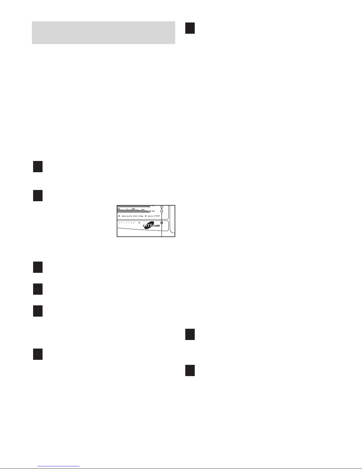
When the key is inserted, the manual
mode will be selected.
To use a program from
our Web site, press the
Program button repeatedly until the iFIT.com indicator lights.
When the on-screen countdown ends, the program
will begin and the walking belt will begin to move.
Hold the handrails, step onto the walking belt, and
begin walking. During the program, an electronic
“chirping” sound will alert you when the speed
and/or incline of the treadmill is about to change.
CAUTION: Always listen for the “chirp” and be
prepared for speed and/or incline changes.
If the speed or incline settings are too high or too
low, you can manually override the settings at any
time by pressing the Speed or Incline buttons on
the console. However, when the next “chirp” is
heard, the speed and/or incline will change to
the next settings for the program.
To stop the walking belt at any time, press the
Stop button on the console. The Time/Incline/
Segment Time display will begin to flash. To
restart the program, press the Start button or the
s
Speed
will begin to move at 1 mph. When the next
“chirp” is heard, the speed and incline will
change to the next settings of the program.
When the program is completed, the walking belt
will stop and the Time/Incline/Segment Time display will begin to flash. Note: To use another program, press the Stop button and go to step 5.
s
button. After a moment, the walking belt
Go to your computer and start an internet
3
connection.
Start your web browser, if necessary, and go to
4
our Web site at www.iFIT.com.
Follow the desired links on our Web site to se-
5
lect a program.
Read and follow the on-line instructions for using a
program.
Follow the on-line instructions to start the
6
program.
When you start the program, an on-screen countdown will begin.
Note: If the speed or incline of the treadmill
does not change when a “chirp” is heard, make
sure that the iFIT.com indicator is lit and that
the Time/Incline/Segment Time display is not
flashing. In addition, make sure that the audio
cable is properly connected, that it is fully
plugged in, and that it is not wrapped around a
power cord.
Follow your progress with the LED track and
8
the displays.
See step 5 on page 13.
When the program is completed, remove the
9
key.
See step 6 on page 16.
22
Page 23
THE INFORMATION MODE/DEMO MODE
The console features an information mode that keeps
rack of the total number of hours that the treadmill has
t
been operated and the total number of miles that the
alking belt has moved. The information mode also al-
w
lows you to switch the console from miles per hour to
kilometers per hour. In addition, the information mode
allows you to turn on and turn off the demo mode.
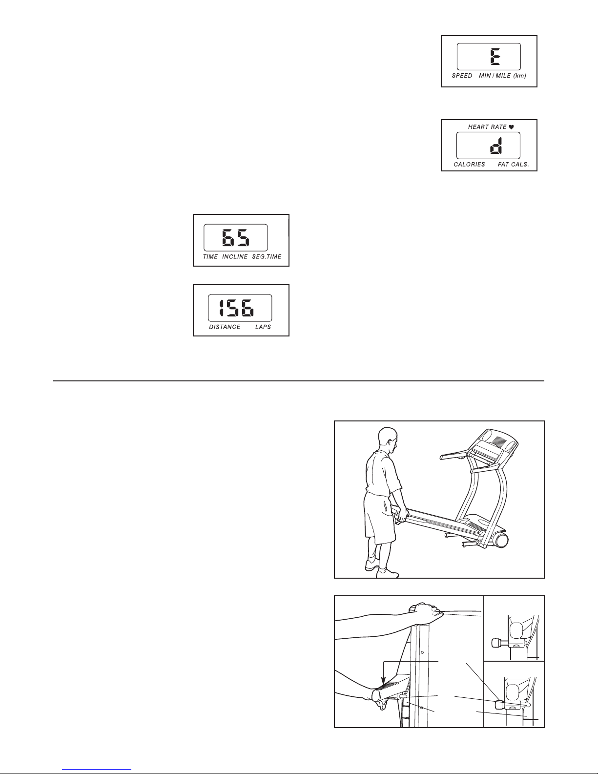
To select the information mode, hold down the Stop
button while inserting the key into the console. When
the information mode is selected, the following information will be shown:
The Time/Incline/Segment
Time display will show the
total number of hours the
treadmill has been used.
The Distance/Laps display will
show the total number of
miles (or kilometers) that the
walking belt has moved.
An “E” for english miles or an
“M” for metric kilometers will
ppear in the Speed/Min-
a
Mile display. Press the
Speed
he unit of measurement.
t
MPORTANT: The Calories/
I
Fat Calories/Heart Rate
display should be blank. If
a “d” appears in the display,
the console is in the “demo”
mode. This mode is intended
to be used only when a treadmill is displayed in a store.
When the console is in the demo mode, the power cord
can be plugged in, the key can be removed from the
console, and the displays and indicators on the console
will automatically light in a preset sequence, although
the buttons on the console will not operate. If a “d” ap-
pears in the Calories/Fat Calories/Heart Rate display
when the information mode is selected, press the
Speed
To exit the information mode, remove the key from the
console.
button to change
ss
button so the display is blank.
t
t
HOW TO FOLD AND MOVE THE TREADMILL
HOW TO FOLD THE TREADMILL FOR STORAGE
Before folding the treadmill, adjust the incline to the
lowest position. If this is not done, the treadmill may be
permanently damaged. Next, unplug the power cord.
CAUTION: You must be able to safely lift 45 pounds (20
kg) in order to raise, lower, or move the treadmill.
1. Hold the treadmill with your hands in the locations shown
at the right. CAUTION: To decrease the possibility of
injury, bend your legs and keep your back straight. As
you raise the treadmill, make sure to lift with your legs
rather than your back. Raise the treadmill about halfway
to the vertical position.
2. Move your right hand to the position shown and hold the
treadmill firmly. Using your left hand, pull the latch knob to
the left and hold it. Raise the treadmill until the foot rail is
past the latch pin. Slowly release the latch knob. Make
sure that the foot rail is securely held by the latch pin.
To protect the floor or carpet from damage, place a
mat under the treadmill. Keep the treadmill out of
direct sunlight. Do not leave the treadmill in the storage position in temperatures above 85° Fahrenheit.
1
2
Latch
Knob
Pin
Foot Rail
Open
Closed
23
Page 24
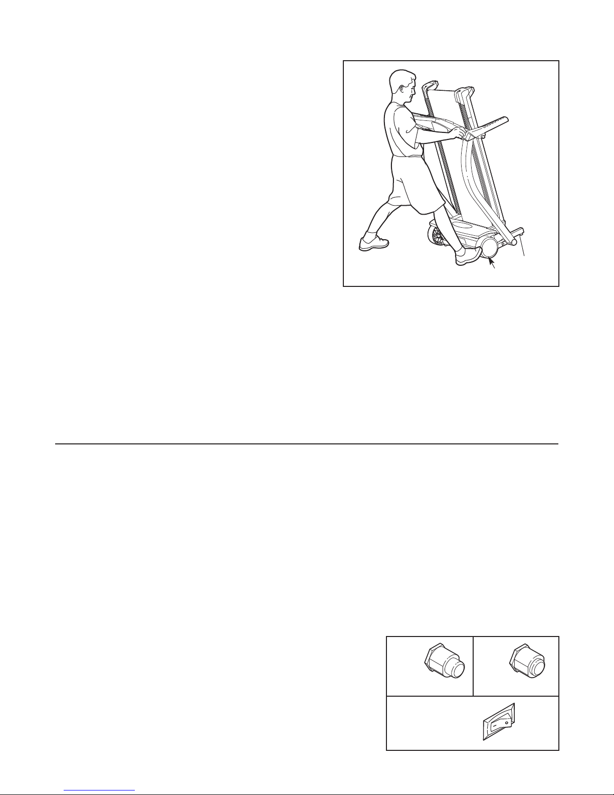
HOW TO MOVE THE TREADMILL
efore moving the treadmill, convert the treadmill to the stor-
B
age position as described above. Make sure that the foot
rail is securely held by the latch pin.
1. Hold the handrails or console as shown and place one
foot against a wheel.
2. Tilt the treadmill back until it rolls freely on the wheels.
Carefully move the treadmill to the desired location.
Never move the treadmill without tipping it back. To
reduce the risk of injury, use extreme caution while
moving the treadmill. Do not attempt to move the
treadmill over an uneven surface.
3. Place one foot on a wheel, and carefully lower the treadmill until it is resting in the storage position.
Base
Wheels
HOW TO LOWER THE TREADMILL FOR USE
1. See drawing 2 on page 23. Hold the treadmill as shown, and pull the lock knob to the left. Pivot the treadmill
down until the frame and the foot rails are past the latch pin. Slowly release the lock knob.
2. See drawing 1 on page 23. Hold the treadmill firmly with both hands, and lower the treadmill to the floor. To
decrease the possibility of injury, bend your legs and keep your back straight.
TROUBLESHOOTING
Most treadmill problems can be solved by following the steps below. Find the symptom that applies, and
follow the steps listed. If further assistance is needed, please call our Customer Service Department tollfree at 1-800-999-3756, Monday through Friday, 6 a.m. until 6 p.m. Mountain Time (excluding holidays).
PROBLEM: The power does not turn on
SOLUTION: a. Make sure that the power cord is plugged into a surge suppressor, and that the surge suppressor
is plugged into a properly grounded outlet (see page 11). Use only a single-outlet surge suppressor that meets all of the specifications described on page 11. Important: The treadmill is not compatible with GFCI-equipped outlets.
b. Make sure that the key is fully inserted into the console.
c. Check the circuit breaker located on the treadmill
near the power cord. If the switch protrudes as
shown, the circuit breaker has tripped. To reset the
circuit breaker, wait for five minutes and then press
the switch back in.
d. Check the on/off switch located on the treadmill near
the power cord. The switch must be in the on position.
c
Tripped
d
Reset
On
Position
24
Page 25
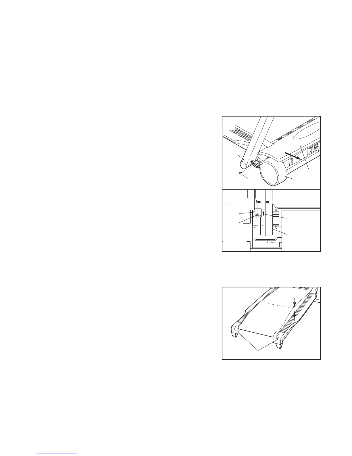
PROBLEM: The power turns off during use
SOLUTION: a. Check the circuit breaker located on the treadmill frame near the power cord (see c. above). If the
ircuit breaker has tripped, wait for five minutes and then press the switch back in.
c
. Make sure that the power cord is plugged in. If the power cord is plugged in, unplug it, wait for
b
five minutes, and then plug it back in.
c. Remove the key from the console. Reinsert the key fully into the console.
d. Make sure that the on/off switch is in the on position.
PROBLEM: The displays of the console do not function properly
SOLUTION: a. Lower the treadmill to the lowest incline level. Unplug
the power cord from the front of the treadmill and
a
remove the key from the console. Remove a Hood
Screw (97) from each side of the Motor Hood (4).
Carefully remove the Motor Hood by pulling the Hood
in the indicated direction.
58
4
97
62
Locate the Reed Switch (13) and the Magnet (126) on
the left side of the Pulley (29). Turn the Pulley until the
Magnet is aligned with the Reed Switch. Loosen the
Reed Switch Screw (12), and slide the Reed Switch
as close as possible to the Magnet; make sure that
the Magnet will not hit the Reed Switch. Retighten
the Screw. Re-attach the hood, and run the treadmill
for a few minutes to check for a correct speed reading.
1/8”
13
12
Top
View
126
29
PROBLEM: The walking belt slows when walked on
SOLUTION: a. Use only a single-outlet surge suppressor that meets all of the specifications described on page 11.
b. If the walking belt is overtightened, treadmill perfor-
mance may decrease and the walking belt may become damaged. Remove the key and UNPLUG THE
POWER CORD. Using the allen wrench, turn both
rear roller adjustment bolts counterclockwise, 1/4 of a
turn. When the walking belt is properly tightened, you
should be able to lift each side of the walking belt 3 to
4 inches off the walking platform. Be careful to keep
the walking belt centered. Plug in the power cord, insert the key and run the treadmill for a few minutes.
Repeat until the walking belt is properly tightened.
c. If the walking belt still slows when walked on, please call our Customer Service Department, toll-
free.
25
b
3”–4”
Rear Roller Adjustment Bolts
Page 26
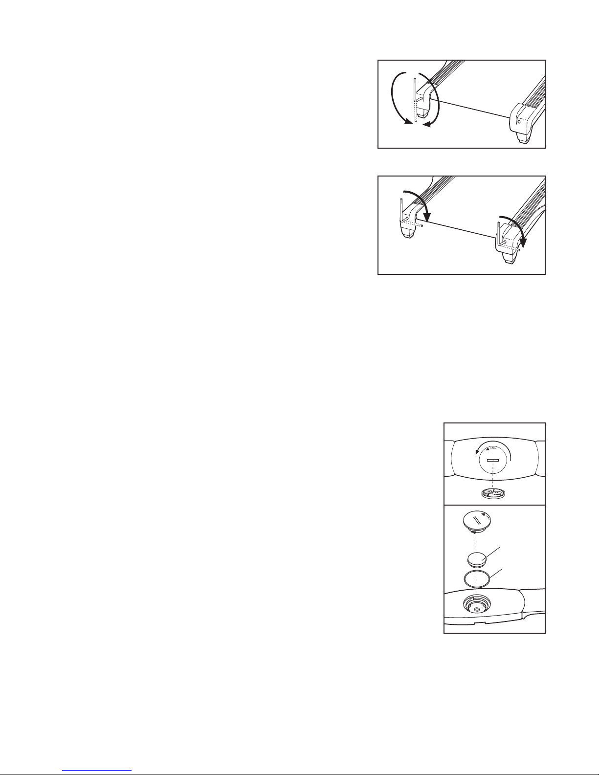
PROBLEM: The walking belt is off-center or slips when walked on
SOLUTION: a. If the walking belt is off-center, first remove the key
nd UNPLUG THE POWER CORD. If the walking
a
a
belt has shifted to the left, use the allen wrench to
urn the left rear roller bolt clockwise 1/2 of a turn; if
t
the walking belt has shifted to the right, turn the
bolt counterclockwise 1/2 of a turn. Be careful not to
overtighten the walking belt. Plug in the power cord,
insert the key and run the treadmill for a few minutes.
Repeat until the walking belt is centered.
b. If the walking belt slips when walked on, first remove
b
the key and UNPLUG THE POWER CORD. Using
the allen wrench, turn both rear roller bolts clockwise,
1/4 of a turn. When the walking belt is correctly tightened, you should be able to lift each side of the walking belt 3 to 4 inches off the walking platform. Be
careful to keep the walking belt centered. Plug in the
power cord, insert the key and carefully walk on the
treadmill for a few minutes. Repeat until the walking
belt is properly tightened.
PROBLEM: The incline of the treadmill does not change correctly or does not change when iFIT.com
CDʼs and videos are played
SOLUTION: a. With the key inserted in the console, press one of the Incline buttons. While the incline is
changing, remove the key. After a few seconds, re-insert the key. The treadmill will automati-
cally rise to the maximum incline level and then return to the minimum level. This will recalibrate
the incline.
PROBLEM: The chest pulse sensor does not function properly
SOLUTION: a. If the chest pulse sensor does not function properly, see CHEST
PULSE SENSOR TROUBLESHOOTING on page 10.
b. If the chest pulse sensor still does not function properly, the battery
should be changed. To replace the battery, locate the battery cover
on the back of the sensor unit. Insert a coin into the slot in the cover
and turn the cover counterclockwise to the “open” position. Remove
the cover.
Next, remove the old battery from the sensor unit. Insert a new CR
2032 battery, making sure that the writing is on top. In addition,
make sure that the rubber gasket is in place in the sensor unit.
Replace the battery cover and turn it to the closed position.
b
CR2032
Battery
Rubber
Gasket
26
Page 27
CONDITIONING GUIDELINES
WARNING:
efore beginning this or any exercise pro-
• B
gram, consult your physician. This is especially important for persons over the age of
35 or persons with pre-existing health problems.
• The pulse sensors are not medical devices.
Various factors, including the user's movement, may affect the accuracy of heart rate
readings. The pulse sensors are intended
only as exercise aids in determining heart
rate trends in general.
The following guidelines will help you to plan your exercise program. For more detailed exercise information, obtain a reputable book or consult your physician.
EXERCISE INTENSITY
uses easily accessible carbohydrate calories for energy. Only after the first few minutes does your body
begin to use stored fat calories for energy. If your goal
is to burn fat, adjust the speed and incline of the treadmill until your heart rate is near the lowest number in
our training zone.
y
For maximum fat burning, adjust the speed and incline
of the treadmill until your heart rate is near the middle
number in your training zone.
Aerobic Exercise
If your goal is to strengthen your cardiovascular system, your exercise must be “aerobic.” Aerobic exercise
is activity that requires large amounts of oxygen for
prolonged periods of time. This increases the demand
on the heart to pump blood to the muscles, and on the
lungs to oxygenate the blood. For aerobic exercise,
adjust the speed and incline of the treadmill until your
heart rate is near the highest number in your training
zone.
Whether your goal is to burn fat or to strengthen your
cardiovascular system, the key to achieving the
desired results is to exercise with the proper intensity.
The proper intensity level can be found by using your
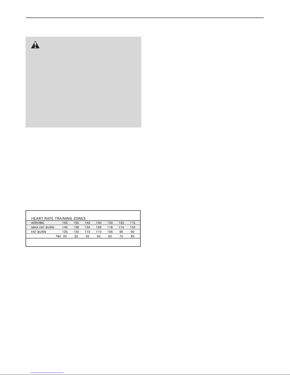
heart rate as a guide. The chart below shows recommended heart rates for fat burning and aerobic exercise.
To find the proper heart rate for you, first find your age
near the bottom of the chart (ages are rounded off to
the nearest ten years). Next, find the three numbers
above your age. The three numbers define your “training zone.” The lower two numbers are recommended
heart rates for fat burning; the higher number is the
recommended heart rate for aerobic exercise.
To measure your heart rate during exercise, use the
pulse sensor.
Fat Burning
To burn fat effectively, you must exercise at a relatively
low intensity level for a sustained period of time.
During the first few minutes of exercise, your body
WORKOUT GUIDELINES
Each workout should include the following three parts:
A Warm-up—Start each workout with 5 to 10 minutes
of stretching and light exercise. A proper warm-up increases your body temperature, heart rate and circulation in preparation for exercise.
Training Zone Exercise—After warming up, increase
the intensity of your exercise until your pulse is in your
training zone for 20 to 60 minutes. (During the first few
weeks of your exercise program, do not keep your
pulse in your training zone for longer than 20 minutes.)
Breathe regularly and deeply as you exercise—never
hold your breath.
A Cool-down—Finish each workout with 5 to 10 minutes of stretching to cool down. This will increase the
flexibility of your muscles and will help prevent post-exercise problems.
EXERCISE FREQUENCY
To maintain or improve your condition, complete three
workouts each week, with at least one day of rest between workouts. After a few months, you may complete up to five workouts each week if desired. The key
to success is to make exercise a regular and enjoyable
part of your everyday life.
27
Page 28
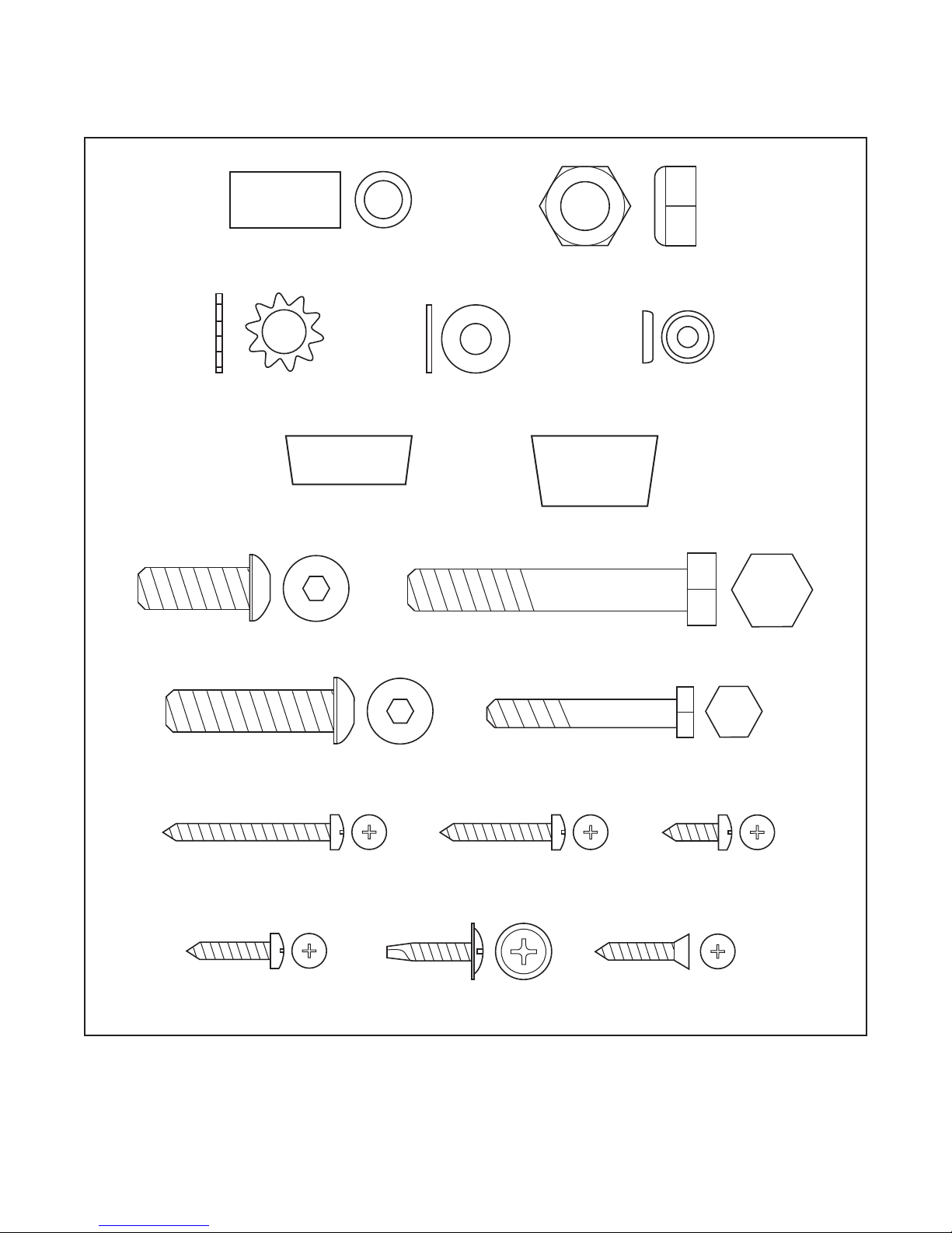
Extension Leg Screw (34)–2
3/8” x 2" Bolt (43)–4
1/2" Screw (59)–2
1/4” x 1” Bolt (23)–4
Star Washer (113)–6
Upright Bolt (66)–2
Console Bolt (42)–4
Post Bolt (44)–4
Foot Housing Screw (105)–4
Latch Screw (36)–2
1/2" Screw (51)–14
3/4” Screw (12)–12
Foot Screw (65)–4
1/4” Washer (125)–4
Foot Rail Washer (96)–10
Handrail Spacer (43)–2
Base Leg Bolt (77)–4
Base Leg Nut (70)–4
Base Leg Bolt (77)–4
Thick Base Pad (75)–2
Thin Base Pad (103)–2
Foot Rail Screw (97)–10
Remove this chart and use it to identify small parts during assembly. Save
this chart and the EXPLODED DRAWING/PART LIST for future reference.
Page 29

PART LIST —Model No. RBTL69921 R0803A
Key
o. Qty. Description
N
11Decal
24Pulse Sensor Plate
1 Hood Cover
3
41Motor Hood
52Tinnerman Clip
61Left Foot Rail
71Motor Belt
81Frame Pivot Nut
91Lift Frame
10 1 Incline Decal
11 2 Frame Spacer
12 15 3/4” Screw
13 1 Reed Switch
14 1 Jack
15 4 Motor Bolt
16 4 Electronics Screw
17 1 Controller
18 1 Electronics Bracket
19 1 Power Board
20 4 Plastic Stand-off
21 1 Left Top Handgrip
22 1 Chest Pulse
23 1 Chest Pulse Strap
24 1 IFit.com Video
25 1 Motor Tension Bolt
26 1 Motor Tension Washer
27 4 Cage Nut
28 1 Flywheel
29 1 Front Roller/Pulley
30 1 Motor
31* 1 Motor Assembly
32 1 Front Roller Adj. Bolt
33 1 Console/
Pulse Bar Wire
34 1 Motor Controller Wire
35 1 Left Upright
36 2 Latch Screw
37 1 Latch Assembly
38 2 Choke Bracket Bolt
39 1 Latch Spacer
40 1 Left Bottom Handgrip
41 2 Handgrip Post
42 4 Console Bolt
43 2 Post Spacer
44 4 Post Bolt
45 2 Releaseable Wire Tie
46 1 Console Insert
47 1 Console Base, Front
48 1 Cup Holder, Left
49 1 Book Rack
50 1 Cup Holder, Right
51 33 1/2” Screw
Key
o. Qty. Description
N
52 1 Console Base, Back
53 1 Right Top Handgrip
4 1 Right Bottom Handgrip
5
55 1 Wire Harness
56 1 Frame Pivot Bolt,
Left
57 2 Key/Clip
58 1 Right Upright
59 2 Front Wheel Cover
60 2 Front Wheel Bolt
61 2 Spring Washer
62 2 Front Wheel
63 2 Front Wheel Nut
64 1 Wheel Bracket, Right
65 4 Foot Screw
66 2 Upright Bolt
67 2 Upright Endcap
68 3 Warning Decal
69 2 Incline Pivot Bolt
70 4 Base Leg Nut
71 1 Tension Cage Nut
72 1 Incline Motor
73 1 Incline Stop Bracket
74 1 Incline Motor
Bolt, Top
75 4 Thick Base Pad
76 1 Incline Motor
Bolt, Bottom
77 4 Base Leg Bolt
78 2 Base Leg
79 3 Tie Block
80 1 Ground Screw
81 2 12” Ground Wire
82 2 Belly Pan
Screw, Long
83 1 Belly Pan
84 1 Pulse Wire Harness
85 1 iFit Wire Nut
86 2 Static Decal
87 1 Breaker Nut
88 1 Receptical
89 1 Circuit Breaker
90 1 Belly Pan Plug
91 1 On/Off Switch
92 1 IFit Wire
93 1 Power Cord
94 4 Belt Guide Screw
95 1 Belt Guide
96 10 Foot Rail Washer
97 10 Foot Rail Screw
98 1 Right Foot Rail
99 1 Frame
Key
o. Qty. Description
N
100 1 Walking Platform
101 1 Walking Belt
02 2 Latch Decal
1
103 2 Thin Base Pad
104 2 Rubber Foot
105 4 Foot Housing Screw
106 1 Right Foot Housing
107 2 Roller Adj. Washer
108 2 Rear Roller Adj. Bolt
109 1 Allen Wrench
110 1 Left Foot Housing
111 1 Rear Roller
112 1 IFit Wire
113 6 Star Washer
114 6 Walking Platform
Screw
115 1 Console Ground Wire
116 1 Frame Pivot Bolt,
Right
117 1 Base
118 1 Wheel Bracket, Left
119 1 Console Support
Frame
120 1 Pulse Door
121 2 Base Leg Endcap
122 2 Base Endcap
123 4 Wire Tie
124 1 Belly Pan Wire
Harness
125 5 1/4” Washer
126 1 Magnet
127 2 Incline Bolt
128 2 Motor Bracket Screw
129 1 Mat
130 1 Pulse Receiver
131 1 Motor Bracket
132 1 Console Wire Harness
133 1 Roller Ground Wire
134 1 IFit.com CD
135 1 Incline Motor Nut
#114” Blue Wire, 2F
#14” Blue Wire, 2F
#114” White Wire, M/F
#110” White Wire, 2F
#14” Black Wire, 2F
#14” Red Wire, M/F
#125” Wire Harness
#1User's Manual
# These parts are not illustrated
* Includes all parts shown in the
box
Page 30
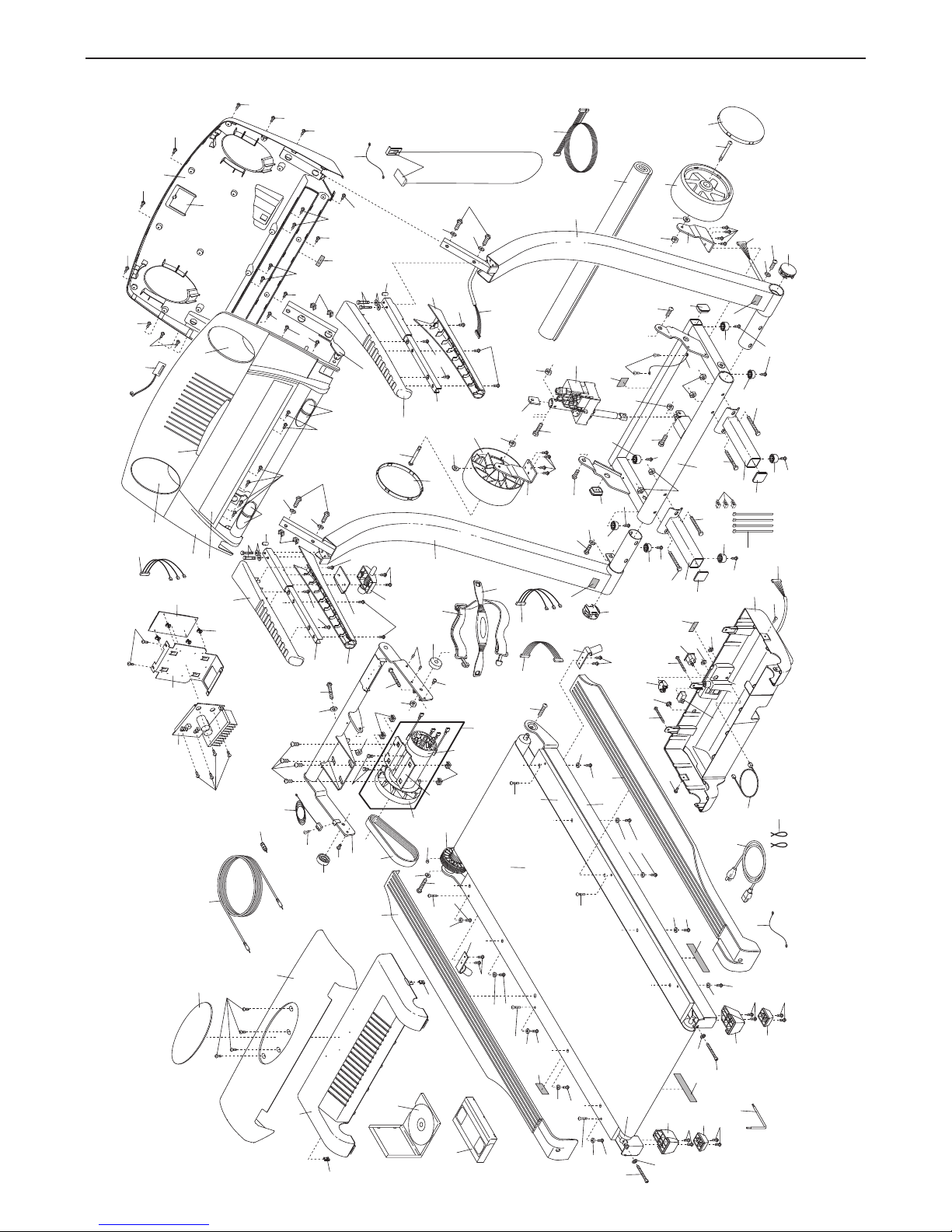
K
i
r
k
N
i
e
b
e
r
g
a
l
l
P
R
O
D
U
C
T
L
I
T
.
G
R
O
U
P
27
7
31*
27
15
30
28
97
83
82
89
88
87
92
85
91
82
97
90
86
127
32
8
17
25
127
9
13
12
74
135
72
66
70
76
135
70
77
73
68
63
62
60
59
64
12
69
61
62
60
59
118
12
77
78
77
77
75
12
75
12
78
68
67
67
66
63
61
53
41
54
26
18
20
19
109
93
94
95
95
11
97
96
97
96
97
96
93
98
6
108
107
110
104
96
96
97
96
97
96
97
4
5
5
3
51
21
41
40
38
36
37
51
39
47
46
48
49
50
52
44
43
42
69
42
44
43
35
58
29
101
100
106
65
104
65
108
107
111
99
11
51
2
51
51
51
51
51
51
51
51
51
51
51
51
51
51
51
51
16
1
112
14
75
12
75
12
55
55
79
97
96
102
97
96
97
57
33
34
86
51
51
51
51
105
105
51
51
113
113
113
113
113
113
125
125
114
114
114
114
114
102
10
121
121
71
2
84
27
27
117
119
120
115
123
45
124
126
81
80
116
56
122
122
68
103
103
12
75
12
129
23
22
134
24
125
131
128
132
133
130
EXPLODED DRAWING —Model No. RBTL69921 R0803A
Page 31

ORDERING REPLACEMENT PARTS
To order replacement parts, call our Customer Service Department toll-free at 1-800-999-3756, Monday through
Friday, 6 a.m. until 6 p.m. Mountain Time (excluding holidays). When ordering parts, please be prepared to give
the following information:
• The MODEL NUMBER OF THE PRODUCT (RBTL69921)
• The NAME OF THE PRODUCT (REEBOK®RX 820 treadmill)
• The SERIAL NUMBER OF THE PRODUCT (see the front cover of this manual)
• The KEY NUMBER AND DESCRIPTION OF THE PART(S) (see the EXPLODED DRAWING and PART LIST
attached in the center of this manual)
LIMITED WARRANTY
ICON Health & Fitness, Inc. (ICON), warrants this product to be free from defects in workmanship and
material, under normal use and service conditions, for a period of ninety (90) days from the date of purchase. This warranty extends only to the original purchaser. ICON's obligation under this warranty is limited to replacing or repairing, at ICON's option, the product through one of its authorized service centers.
All repairs for which warranty claims are made must be pre-authorized by ICON. This warranty does not
extend to any product or damage to a product caused by or attributable to freight damage, abuse, misuse, improper or abnormal usage or repairs not provided by an ICON authorized service center; products used for commercial or rental purposes; or products used as store display models. No other warranty beyond that specifically set forth above is authorized by ICON.
ICON is not responsible or liable for indirect, special or consequential damages arising out of or in connection with the use or performance of the product or damages with respect to any economic loss, loss
of property, loss of revenues or profits, loss of enjoyment or use, costs of removal or installation or other
consequential damages of whatsoever nature. Some states do not allow the exclusion or limitation of incidental or consequential damages. Accordingly, the above limitation may not apply to you.
The warranty extended hereunder is in lieu of any and all other warranties and any implied warranties of
merchantability or fitness for a particular purpose is limited in its scope and duration to the terms set
forth herein. Some states do not allow limitations on how long an implied warranty lasts. Accordingly, the
above limitation may not apply to you.
This warranty gives you specific legal rights. You may also have other rights which vary from state to
state.
ICON HEALTH & FITNESS, INC., 1500 S. 1000 W., LOGAN, UT 84321-9813
Part No. 195381 R0803A Printed in USA © 2003 ICON Health & Fitness, Inc.
 Loading...