

Reebok RBTL97105.0 User Manual
Model No. RBTL97105.0
Visit our website at
www.reebokhomefitness.com
new products, prizes,
fitness tips, and much more!
®
®
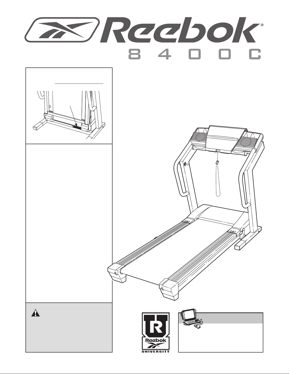
Serial No.
Serial
Number
Decal
QUESTIONS?
As a manufacturer, we are committed to providing complete
customer satisfaction. If you
have questions, or if parts are
damaged or missing, PLEASE
CONTACT OUR CUSTOMER
SERVICE DEPARTMENT
DIRECTLY.
CALL TOLL-FREE:
1-877-994-4999
Mon.–Fri., 6 a.m.–6 p.m. MST
USER'S MANUAL
ON THE WEB:
www.reebokservice.com
CAUTION
Read all precautions and instructions in this manual before using
this equipment. Save this manual
for future reference.

TABLE OF CONTENTS
IMPORTANT PRECAUTIONS . . . . . . . . . . . . . . . . . . . . . . . . . . . . . . . . . . . . . . . . . . . . . . . . . . . . . . . . . . . . . . . . .3
BEFORE YOU BEGIN . . . . . . . . . . . . . . . . . . . . . . . . . . . . . . . . . . . . . . . . . . . . . . . . . . . . . . . . . . . . . . . . . . . . . . .5
ASSEMBLY . . . . . . . . . . . . . . . . . . . . . . . . . . . . . . . . . . . . . . . . . . . . . . . . . . . . . . . . . . . . . . . . . . . . . . . . . . . . . . .6
OPERATION AND ADJUSTMENT . . . . . . . . . . . . . . . . . . . . . . . . . . . . . . . . . . . . . . . . . . . . . . . . . . . . . . . . . . . .10
HOW TO FOLD AND MOVE THE TREADMILL . . . . . . . . . . . . . . . . . . . . . . . . . . . . . . . . . . . . . . . . . . . . . . . . . .20
TROUBLESHOOTING . . . . . . . . . . . . . . . . . . . . . . . . . . . . . . . . . . . . . . . . . . . . . . . . . . . . . . . . . . . . . . . . . . . . . .22
CONDITIONING GUIDELINES . . . . . . . . . . . . . . . . . . . . . . . . . . . . . . . . . . . . . . . . . . . . . . . . . . . . . . . . . . . . . . .24
PART LIST . . . . . . . . . . . . . . . . . . . . . . . . . . . . . . . . . . . . . . . . . . . . . . . . . . . . . . . . . . . . . . . . . . . . . . . . . . . . . . .26
LIMITED WARRANTY . . . . . . . . . . . . . . . . . . . . . . . . . . . . . . . . . . . . . . . . . . . . . . . . . . . . . . . . . . . . . . .Back Cover
Note: An EXPLODED DRAWING is attached in the center of this manual.
REEBOK and the Vector Logo are registered trademarks and service marks of Reebok. This product is
manufactured and distributed under license from Reebok International.
2

IMPORTANT PRECAUTIONS
WARNING: To reduce the risk of burns, fire, electric shock, or injury to persons, read the
following important precautions and information before operating the treadmill.
1. It is the responsibility of the owner to ensure
that all users of this treadmill are adequately
informed of all warnings and precautions.
2. Use the treadmill only as described.
3. Place the treadmill on a level surface, with at
least eight feet of clearance behind it and two
feet on each side. Do not place the treadmill
on any surface that blocks air openings. To
protect the floor or carpet from damage, place
a mat under the treadmill.
4. Keep the treadmill indoors, away from moisture and dust. Do not put the treadmill in a
garage or covered patio, or near water.
5. Do not operate the treadmill where aerosol
products are used or where oxygen is being
administered.
6. Keep children under the age of 12 and pets
away from the treadmill at all times.
7. The treadmill should not be used by persons
weighing more than 325 pounds.
manual and order part number 146148, or see
your local electronics store.
12. Failure to use a properly functioning surge
suppressor could result in damage to the control system of the treadmill. If the control system is damaged, the walking belt may change
speed, accelerate, or stop unexpectedly,
which may result in a fall and serious injury.
13. Keep the power cord and the surge suppressor away from heated surfaces.
14. Never move the walking belt while the power
is turned off. Do not operate the treadmill if
the power cord or plug is damaged, or if the
treadmill is not working properly. (See
TROUBLESHOOTING on page 22 if the treadmill is not working properly.)
15. Read, understand, and test the emergency
stop procedure before using the treadmill (see
HOW TO TURN ON THE POWER on page 12).
16. Never start the treadmill while you are standing on the walking belt. Always hold the
handrails while using the treadmill.
8. Never allow more than one person on the
treadmill at a time.
9. Wear appropriate exercise clothes when
using the treadmill. Do not wear loose clothes
that could become caught in the treadmill.
Athletic support clothes are recommended for
both men and women.
Always wear athletic
shoes. Never use the treadmill with bare feet,
wearing only stockings, or in sandals.
10. When connecting the power cord (see page 10),
plug the power cord into a surge suppressor
(not included) and plug the surge suppressor
into a grounded circuit capable of carrying 15
or more amps. No other appliance should be on
the same circuit. Do not use an extension cord.
11. Use only a single-outlet surge suppressor that
meets all of the specifications described on
page 10. To purchase a surge suppressor, see
your local
telephone number on the front cover of this
REEBOK
dealer or call
the toll-free
17. The treadmill is capable of high speeds.
Adjust the speed in small increments to avoid
sudden jumps in speed.
18. The pulse sensor is not medical device.
Various factors, including the user's movement, may affect the accuracy of heart rate
readings. The pulse sensor is intended only
as an exercise aid in determining heart rate
trends in general.
19. Never leave the treadmill unattended while it
is running. Always remove the key and unplug the power cord when the treadmill is not
in use.
20. Do not attempt to raise, lower, or move the
treadmill until it is properly assembled. (See
ASSEMBLY on page 6, and HOW TO FOLD
AND MOVE THE TREADMILL on page 20.) You
must be able to safely lift 45 pounds (20 kg) to
raise, lower, or move the treadmill.
3
1. Do not change the incline of the treadmill by
2
lacing objects under the treadmill.
p
22. When folding or moving the treadmill, make
sure that the storage latch is fully closed.
23. Inspect and properly tighten all parts of the
treadmill regularly.
24. Never insert or drop any object into any
opening.
25.
DANGER: Always unplug the power
ord immediately after use, before cleaning
c
the treadmill, and before performing the maintenance and adjustment procedures described in this manual. Never remove the
motor hood unless instructed to do so by an
uthorized service representative. Servicing
a
other than the procedures in this manual
hould be performed by an authorized service
s
representative only.
26. This treadmill is intended for in-home use
only. Do not use this treadmill in any commercial, rental, or institutional setting.
WARNING: Before beginning this or any exercise program, consult your physician. This
is especially important for persons over the age of 35 or persons with pre-existing health problems.
Read all instructions before using. ICON assumes no responsibility for personal injury or property
damage sustained by or through the use of this product.
SAVE THESE INSTRUCTIONS
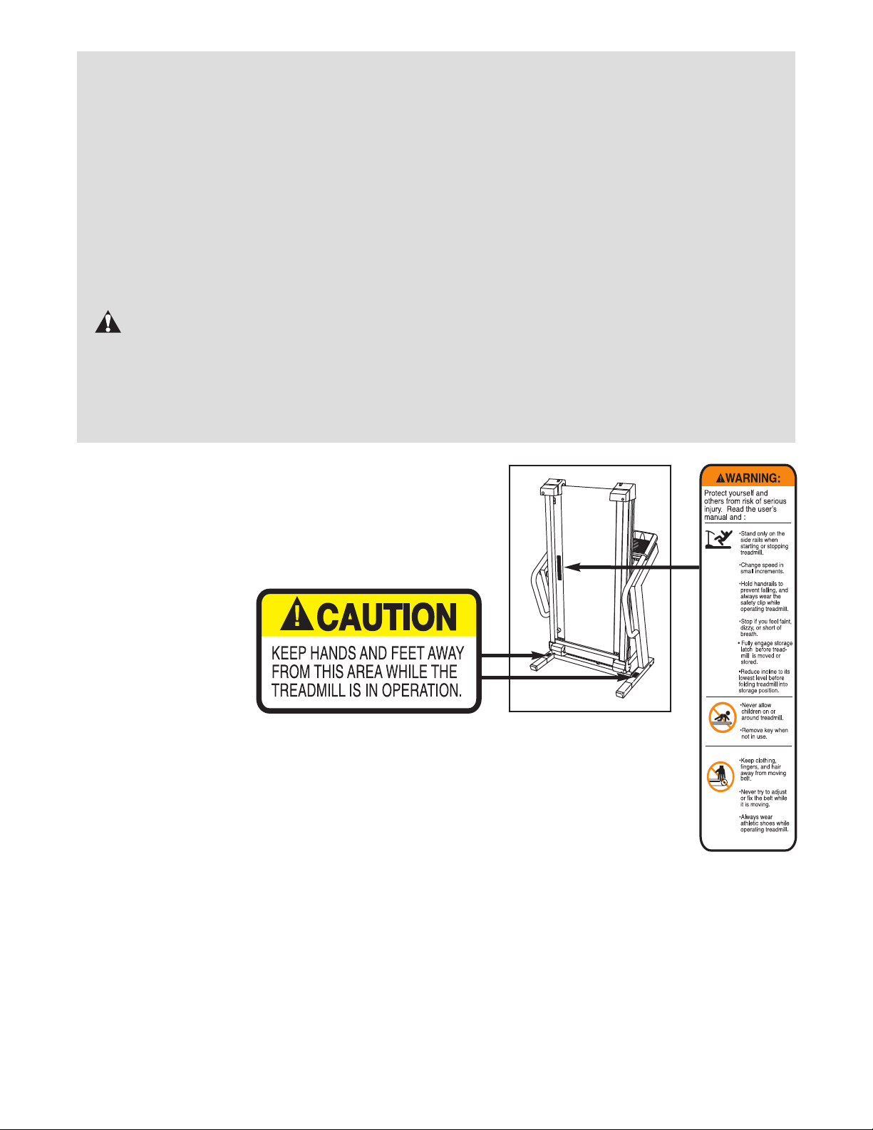
The decals shown here have been placed on the treadmill.
If a decal is missing, or if it is not legible, call the toll-free
telephone number on the front cover of this manual and
order a free replacement decal. Apply the decal in the location shown. Note: The decals are not shown at actual size.
4
BEFORE YOU BEGIN
Thank you for selecting the revolutionary REEBOK
8400 C treadmill. The 8400 C treadmill offers a selection of features designed to make your workouts at
home more effective and enjoyable. And when you’re
not exercising, the unique 8400 C treadmill can be
folded up, requiring less than half the floor space than
traditional treadmills.
For your benefit, read this manual carefully before
you use the treadmill. If you have questions after
reading this manual, please see the front cover of this
manual. To help us assist you, note the product model
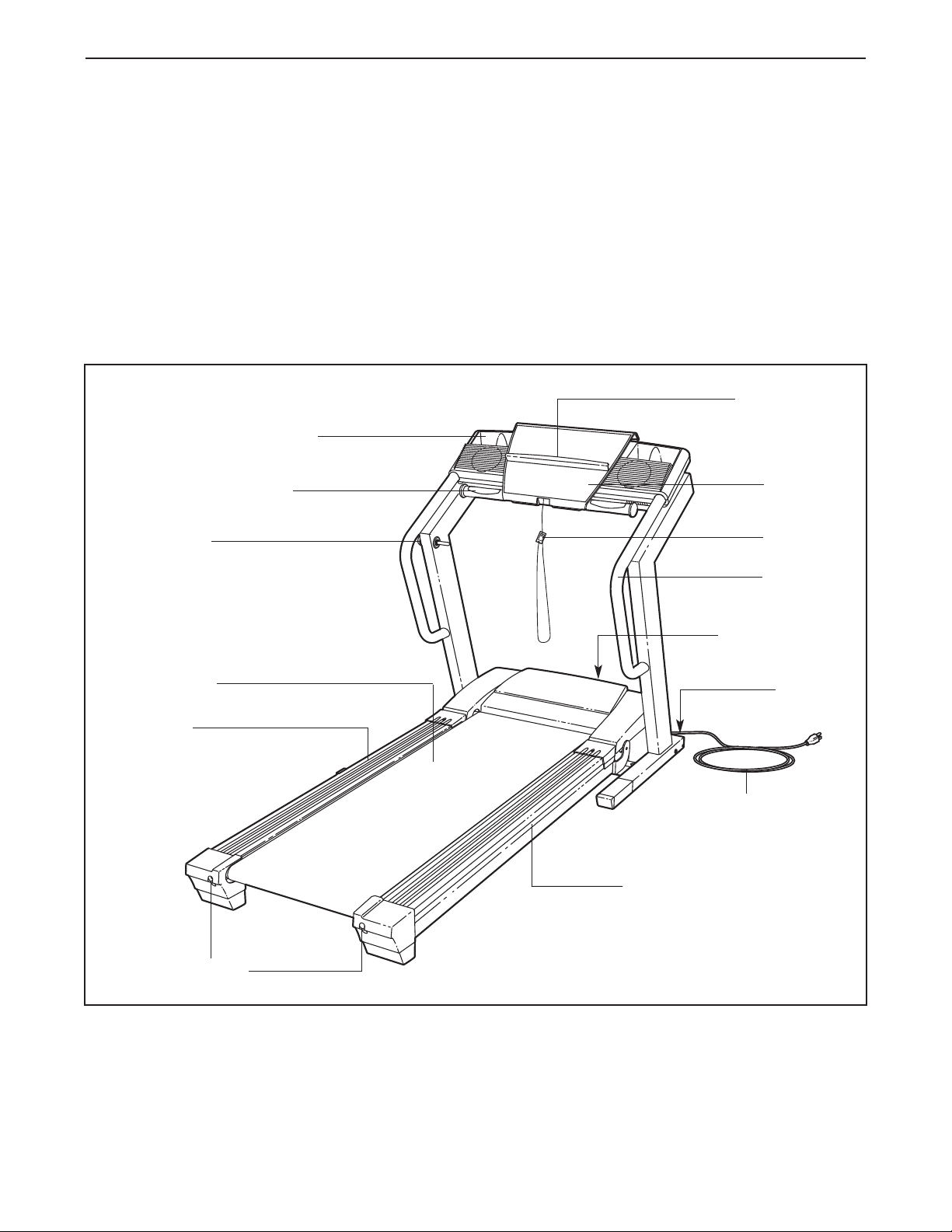
Water Bottle Holder
(no water bottle is included)
Handgrip Pulse Sensor
Latch Knob
®
number and serial number before contacting us. The
model number of the treadmill is RBTL97105.0. The
serial number can be found on a decal attached to the
treadmill (see the front cover of this manual for the location).
To avoid a registration fee for any service needed
under warranty, you must register the treadmill at
www.reebokservice.com/registration.
Before reading further, please review the drawing
below and familiarize yourself with the labeled parts.
Book Holder
Console
Key/Clip
Walking Belt
Foot Rail
Rear Roller
Adjustment Bolts
Handrail
Reset/Off
Circuit Breaker
Wheel
Power Cord
Cushioned Walking Platform
RIGHT SIDE
5

ASSEMBLY
Handrail Star
Washer (77)–2
Foot Screw (74)–2
1 1/4” Tek Screw (71)–2
1
Wheel Bolt (94)–2
Nut (20)–2
1” Tek Screw (100)–4
Console Bolt (78)–2
3/4” Tek Screw (65)–2
ssembly requires two persons.Set the treadmill in a cleared area and remove all packing materials. Do not
A
dispose of the packing materials until assembly is completed. Assembly requires the included allen wrench
and your own phillips screwdriver , wire cutters , and rubber mallet .
Note: The underside of the treadmill walking belt is coated with high-performance lubricant. During shipping, a
small amount of lubricant may be transferred to the top of the walking belt or the shipping carton. This is a normal
condition and does not affect treadmill performance. If there is lubricant on top of the walking belt, simply wipe off
the lubricant with a soft cloth and a mild, non-abrasive cleaner.
To identify small parts during assembly, use the part identification drawings below. To avoid damaging
plastic parts, do not use power tools for assembly.
1. With the help of a second person, carefully raise the
Uprights (69) to the position shown.
Next, insert one of the Extension Legs (102) into the base
of the Uprights (69) as shown. Make sure that the
Extension Leg is turned so the Base Pad (99) is un
derneath it. Note: It may be helpful to tip the Uprights for-
ward and use a rubber mallet to fully insert the Extension
Leg.
Insert the other Extension Leg (not shown) in the same
way.
-
1
69
102
99
6
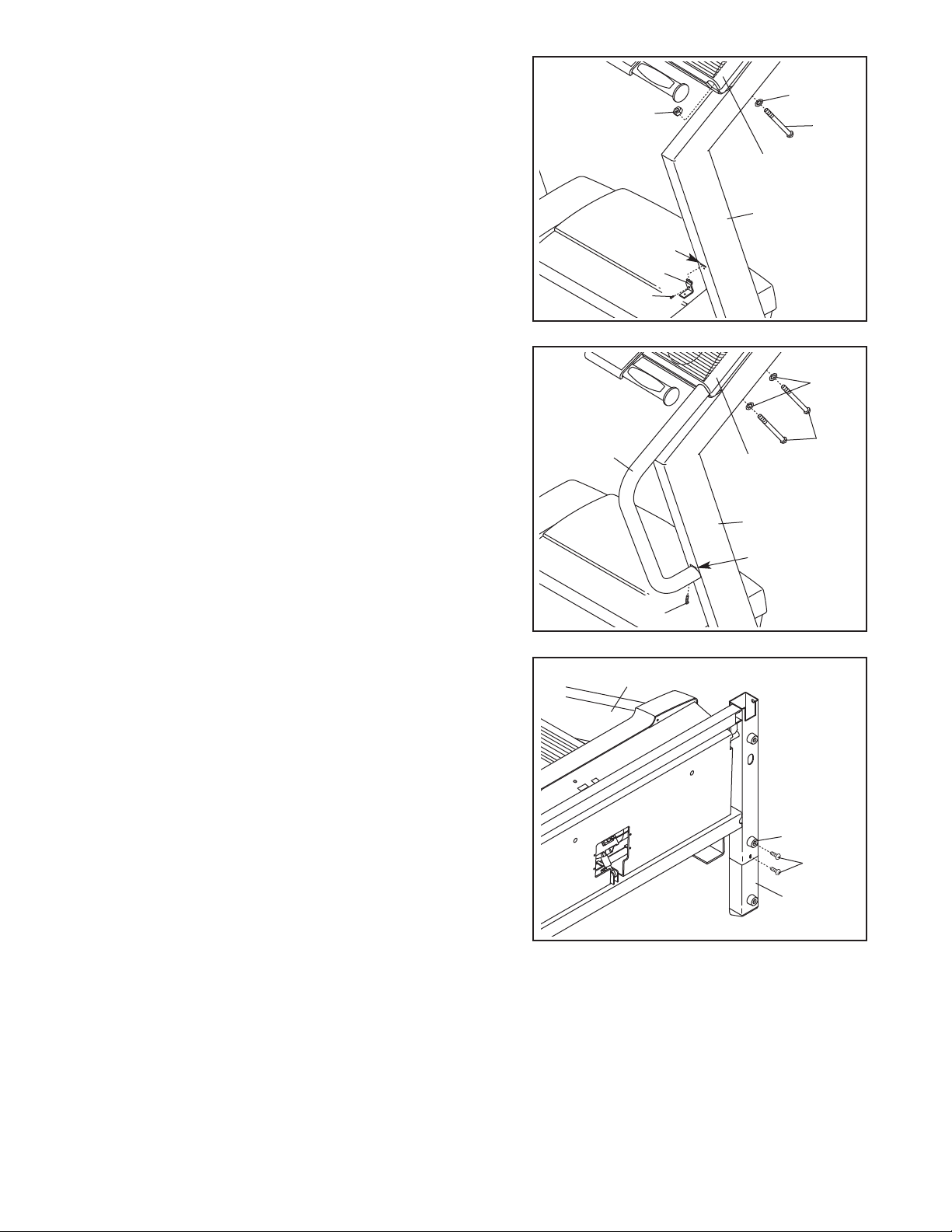
2. Insert the tab on one of the Handrail Brackets (70) into
the indicated slot in the right Upright (69). Attach the
andrail Bracket with a 3/4” Tek Screw (65).
H
ttach the other Handrail Bracket (not shown) to the left
A
Upright (not shown) the same way.
While a second person holds the console assembly, remove the Console Bolts (78), the Handrail Star Washers
(77), and the Nuts (A) from both Uprights (69) and the
console assembly. Discard the Nuts.
2
77
A
Console
Assembly
69
Slot
70
65
78
3. While a second person holds the console assembly, insert
the upper end of one of the Handrails (55) into the console
assembly; make sure that the Handrail Bracket (70) is inside of the lower end of the Handrail. Tighten a 1 1/4” Tek
Screw (71) into the bottom of the Handrail. Repeat with
the other Handrail on the left side (not shown).
Next, insert two Console Bolts (78) with Handrail Star
Washers (77) into the right Upright (69) and the Handrail
(55). Finger tighten the Console Bolts;
the Console Bolts yet. Repeat with the Handrail on the
left side (not shown). After all four Console Bolts have
been started, tighten them.
4. With the help of a second person, carefully tip the
Uprights (69) down as shown. Make sure that the
Extension Legs (102) remain in the Uprights.
Attach each Extension Leg (102) with two 1” Tek Screws
(100) and one Base Pad (99) as shown; attach the lower
Tek Screw, without the Base Pad, first. Note: One replacement Base Pad may be included. Use the Base Pad
to replace any Base Pad that becomes worn.
do not fully tighten
3
77
55
71
4
69
Console
Assembly
69
70
78
99
100
102
7
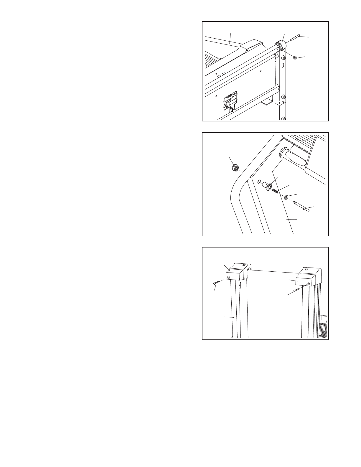
5. Attach a Wheel (95) to the base of the Uprights (69) with
a Wheel Bolt (94) and a Nut (20). Do not overtighten
he Nut; the Wheel should turn freely. Attach the other
t
heel (not shown) in the same way.
W
With the help of a second person, carefully raise the
Uprights (69) to a vertical position.
5
69
95
94
0
2
6. Press the Latch Knob Sleeve (56) into the left Upright
(69). If necessary, use a rubber mallet to fully insert the
Latch Knob Sleeve.
Remove the knob from the pin. Make sure that the collar
and the spring are on the pin. Next, insert the pin into
the Latch Knob Sleeve (56) and the left Upright (69), and
tighten the knob back onto the pin.
7. Place the treadmill in the storage position (see HOW TO
FOLD THE TREADMILL FOR STORAGE on page 20).
Identify the Right Endcap Foot (50). Attach the Right
Endcap Foot to the bottom of the Right Endcap (58) with
a Foot Screw (74).
Next, attach the Left Endcap Foot (49) to the bottom of
the Left Endcap (96) with a Foot Screw (74).
6
Knob
56
Spring
Collar
Pin
69
7
49
50
74
74
Lower the treadmill Frame (110) (see HOW TO LOWER
THE TREADMILL FOR USE on page 21).
8. Make sure that all parts are properly tightened before you use the treadmill. Note: Extra hardware may
be included. Keep the included allen wrench in a secure place; the allen wrench is used to adjust the walking
belt (see page 23). To protect the floor or carpet from damage, place a mat under the treadmill.
110
8
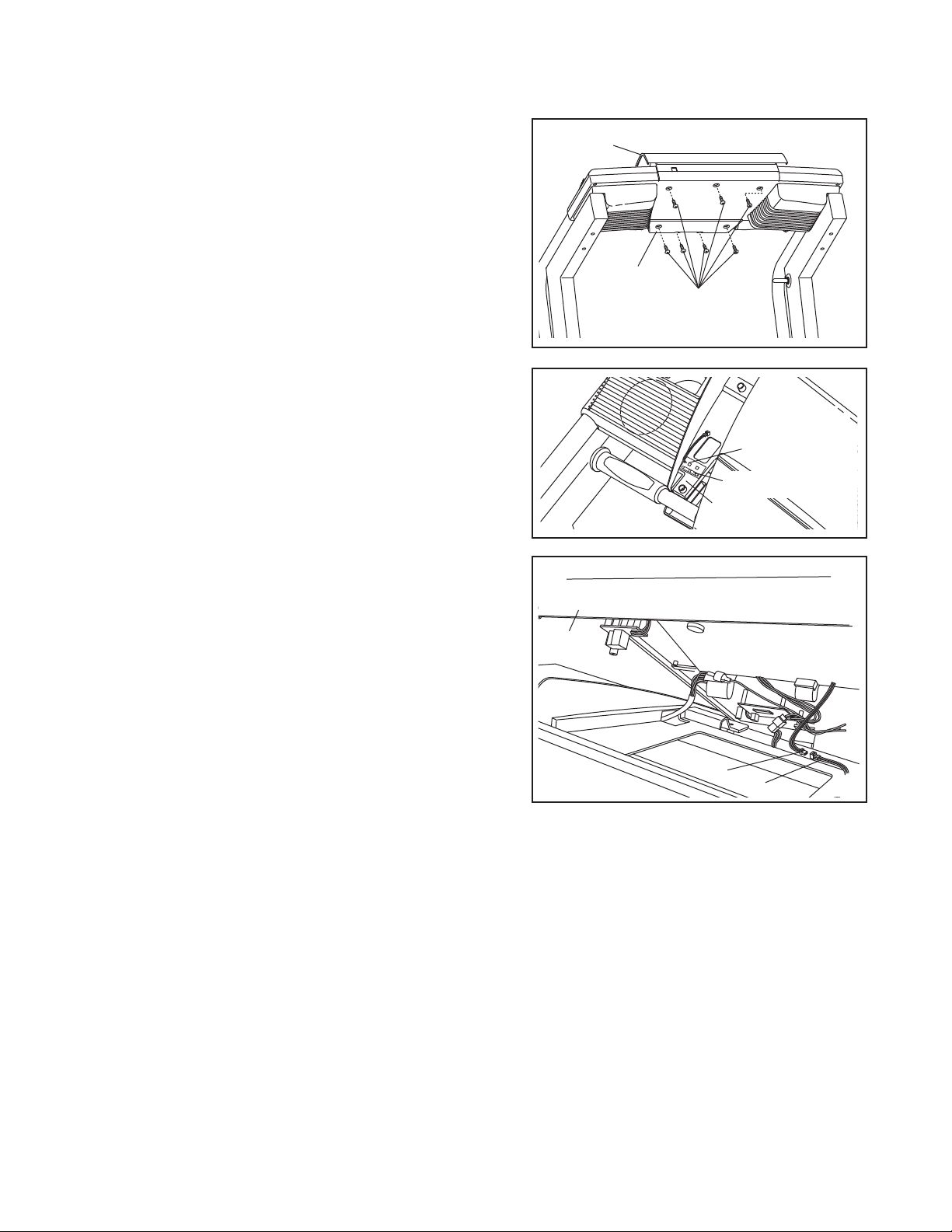
If you purchase the optional chest pulse sensor (see page 19), follow the steps below to install the receiver included with the chest pulse sensor.
ake sure that the power cord is unplugged.Remove
1.M
the indicated screws from the Console Back (88).
(Important: The screws may be different lengths;
make sure to remember the original location of each
screw.) Next, remove the Console Back.
1
82
88
Screws
2. Peel the paper off the pad on the bottom of the receiver
Turn the receiver so the small cylinder is on the
(A).
side shown, and press the receiver into the Console
Base (81) in the indicated location.
3. Connect the wire on the receiver (A) to the end of the
short wire (B) on the underside of the Console (82).
Discard the other wires included with the receiver. Use
the included wire tie to secure the wires, if needed.
Make sure that no wires are pinched. See step 1.
Reattach the Console (82) with the screws. Important: If
the screws are not reattached in their original locations, the Console may be damaged.
2
A
Cylinder
81
3
82
B
A
9
 Loading...