

Reebok RBTL69921 Owner's Manual
®
Visit our website at
www.reebokhomefitness.com
new products, prizes,
fitness tips, and much more!
atent Pending
®
®
P
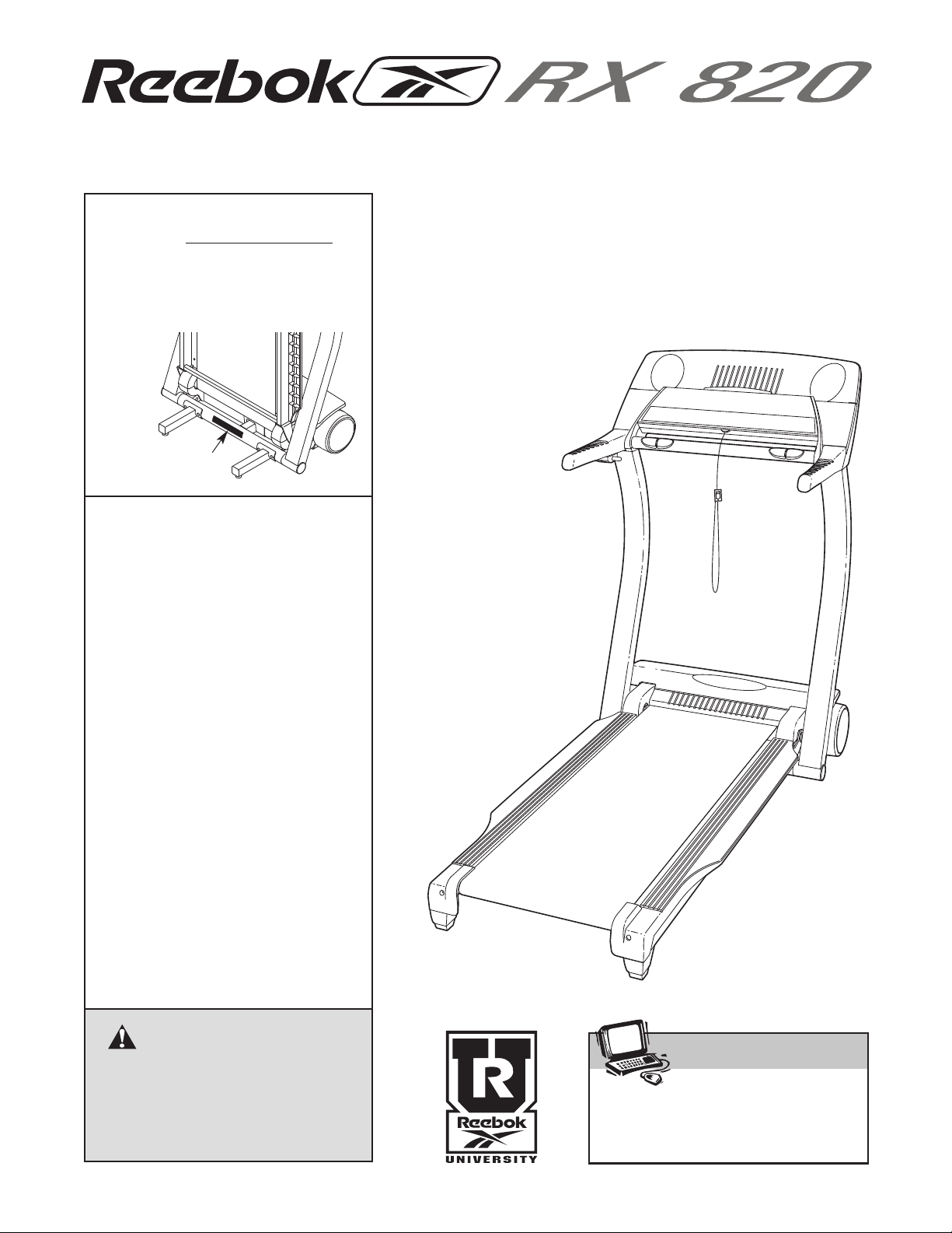
odel No. RBTL69921
M
Serial No.
Find the serial number in the location
shown below. Write the serial number
in the space above for reference.
Serial Number
Decal
QUESTIONS?
If you have questions, or if there
are missing or damaged parts,
we will guarantee complete satisfaction through direct assistance from our factory.
USER'S MANUAL
TO AVOID DELAYS, PLEASE
CALL DIRECT TO OUR TOLLFREE CUSTOMER HOT LINE.
The trained technicians on our
Customer Hot Line will provide
immediate assistance, free of
charge to you.
CUSTOMER HOT LINE:
1-800-999-3756
Mon.–Fri., 6 a.m.–6 p.m. MST
CAUTION
Read all precautions and instructions in this manual before
using this equipment. Save this
manual for future reference.

TABLE OF CONTENTS
®
IMPORTANT PRECAUTIONS . . . . . . . . . . . . . . . . . . . . . . . . . . . . . . . . . . . . . . . . . . . . . . . . . . . . . . . . . . . . . . . . .3
BEFORE YOU BEGIN . . . . . . . . . . . . . . . . . . . . . . . . . . . . . . . . . . . . . . . . . . . . . . . . . . . . . . . . . . . . . . . . . . . . . . .5
ASSEMBLY . . . . . . . . . . . . . . . . . . . . . . . . . . . . . . . . . . . . . . . . . . . . . . . . . . . . . . . . . . . . . . . . . . . . . . . . . . . . . . .6
HOW TO USE THE CHEST PULSE SENSOR . . . . . . . . . . . . . . . . . . . . . . . . . . . . . . . . . . . . . . . . . . . . . . . . . . .10
OPERATION AND ADJUSTMENT . . . . . . . . . . . . . . . . . . . . . . . . . . . . . . . . . . . . . . . . . . . . . . . . . . . . . . . . . . . .11
HOW TO FOLD AND MOVE THE TREADMILL . . . . . . . . . . . . . . . . . . . . . . . . . . . . . . . . . . . . . . . . . . . . . . . . . .23
TROUBLESHOOTING . . . . . . . . . . . . . . . . . . . . . . . . . . . . . . . . . . . . . . . . . . . . . . . . . . . . . . . . . . . . . . . . . . . . . .24
CONDITIONING GUIDELINES . . . . . . . . . . . . . . . . . . . . . . . . . . . . . . . . . . . . . . . . . . . . . . . . . . . . . . . . . . . . . . .27
ORDERING REPLACEMENT PARTS . . . . . . . . . . . . . . . . . . . . . . . . . . . . . . . . . . . . . . . . . . . . . . . . . .Back Cover
LIMITED WARRANTY . . . . . . . . . . . . . . . . . . . . . . . . . . . . . . . . . . . . . . . . . . . . . . . . . . . . . . . . . . . . . . .Back Cover
Note: A PART LIST/EXPLODED DRAWING is attached in the center of this manual.
REEBOK and the Vector Logo are registered trademarks and service marks of Reebok. This product is
manufactured and distributed under license from Reebok International.
2

IMPORTANT PRECAUTIONS
WARNING: To reduce the risk of burns, fire, electric shock, or injury to persons, read the
following important precautions and information before operating the treadmill.
1. It is the responsibility of the owner to ensure
that all users of this treadmill are adequately
informed of all warnings and precautions.
2. Use the treadmill only as described.
3. Place the treadmill on a level surface, with at
least eight feet of clearance behind it and two
feet on each side. Do not place the treadmill
on any surface that blocks air openings. To
protect the floor or carpet from damage, place
a mat under the treadmill.
4. Keep the treadmill indoors, away from moisture and dust. Do not put the treadmill in a
garage or covered patio, or near water.
5. Do not operate the treadmill where aerosol
products are used or where oxygen is being
administered.
6. Keep children under the age of 12 and pets
away from the treadmill at all times.
7. The treadmill should not be used by persons
weighing more than 250 pounds.
8. Never allow more than one person on the
treadmill at a time.
9. Wear appropriate exercise clothes when
using the treadmill. Do not wear loose clothes
that could become caught in the treadmill.
Athletic support clothes are recommended for
both men and women. Always wear athletic
shoes. Never use the treadmill with bare feet,
wearing only stockings, or in sandals.
10. When connecting the power cord (see page 11),
plug the power cord into a surge suppressor
(not included) and plug the surge suppressor
into a grounded circuit capable of carrying 15
or more amps. No other appliance should be on
the same circuit. Do not use an extension cord.
11. Use only a single-outlet surge suppressor that
meets all of the specifications described on
page 10. To purchase a surge suppressor, see
your local REEBOK dealer or call 1-800-8063651 and order part number 146148.
12. Failure to use a properly functioning surge
suppressor could result in damage to the control system of the treadmill. If the control system is damaged, the walking belt may change
speed or stop unexpectedly, which may result
in a fall and serious injury.
13. Keep the power cord and the surge suppressor away from heated surfaces.
14. Never move the walking belt while the power
is turned off. Do not operate the treadmill if
the power cord or plug is damaged, or if the
treadmill is not working properly. (See
BEFORE YOU BEGIN on page 5 if the treadmill is not working properly.)
15. Never start the treadmill while you are standing on the walking belt. Always hold the
handrails while using the treadmill.
16. The treadmill is capable of high speeds.
Adjust the speed in small increments to avoid
sudden jumps in speed.
17. The pulse sensors are not medical devices.
Various factors, including the user's movement, may affect the accuracy of heart rate
readings. The pulse sensors are intended
only as exercise aids in determining heart
rate trends in general.
18. Never leave the treadmill unattended while it
is running. Always remove the key, unplug
the power cord and move the on/off switch to
the off position when the treadmill is not in
use. (See the drawing on page 5 for the location of the on/off switch.)
19. Do not attempt to raise, lower, or move the
treadmill until it is properly assembled. (See
ASSEMBLY on page 6, and HOW TO FOLD
AND MOVE THE TREADMILL on page 23.) You
must be able to safely lift 45 pounds (20 kg) in
order to raise, lower, or move the treadmill.
20. Do not change the incline of the treadmill by
placing objects under the treadmill.
21. When folding or moving the treadmill, make
sure that the storage latch is fully closed.
3
22. When using iFIT.com CDʼs and videos, an
•Fully engage
storage latch
before treadmill
is moved or
stored
•Reduce incline
to its lowest
level before
folding treadmill into storage
position
electronic “chirping” sound will alert you
when the speed and/or incline of the treadmill
is about to change. Always listen for the
chirp” and be prepared for speed and/or in-
“
cline changes. In some instances, the speed
and/or incline may change before the personal trainer describes the change.
23. When using iFIT.com CDʼs and videos, you
can manually override the speed and incline
settings at any time by pressing the speed
and incline buttons. However, when the next
“chirp” is heard, the speed and/or incline will
change to the next settings of the CD or video
program.
25. Inspect and properly tighten all parts of the
treadmill regularly.
26. Never insert or drop any object into any
pening.
o
DANGER: Always unplug the power
27.
cord immediately after use, before cleaning
the treadmill, and before performing the maintenance and adjustment procedures described in this manual. Never remove the
motor hood unless instructed to do so by an
authorized service representative. Servicing
other than the procedures in this manual
should be performed by an authorized service
representative only.
24. Always remove iFIT.com CDʼs and videos
from your CD player or VCR when you are not
using them.
28. This treadmill is intended for in-home use
only. Do not use this treadmill in any commercial, rental, or institutional setting.
WARNING: Before beginning this or any exercise program, consult your physician. This
is especially important for persons over the age of 35 or persons with pre-existing health problems.
Read all instructions before using. ICON assumes no responsibility for personal injury or property
damage sustained by or through the use of this product.
SAVE THESE INSTRUCTIONS
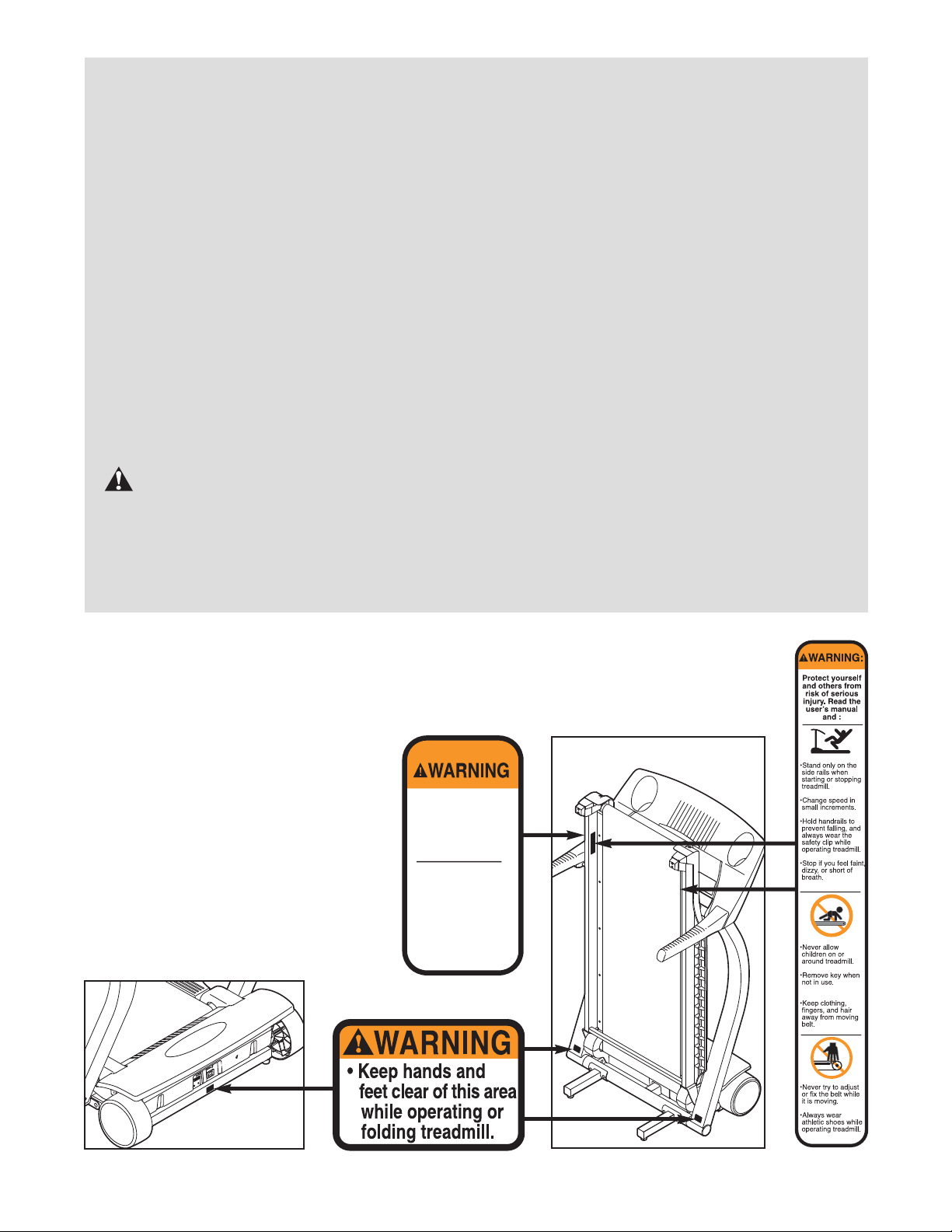
The decals shown below have been placed on your treadmill. If the decal is missing, or if it
is not legible, please call our Customer Service Department, toll-free, to order a free replacement decal (see ORDERING REPLACEMENT PARTS on the back cover of this manual). Apply the decal in the location shown. Note: The decal at the far right is shown at 50%
of actual size. The decal at the right is
shown at 80% of actual size.
4
BEFORE YOU BEGIN
Thank you for selecting the new REEBOK®RX 820
treadmill. The RX 820 treadmill combines advanced
echnology with innovative design to help you get the
t
most from your exercise program in the convenience of
your home. And when youʼre not exercising, the unique
RX 820 can be folded up, requiring less than half the
floor space of other treadmills.
For your benefit, read this manual carefully before
using the treadmill. If you have questions after read-
ing this manual, please call our Customer Service
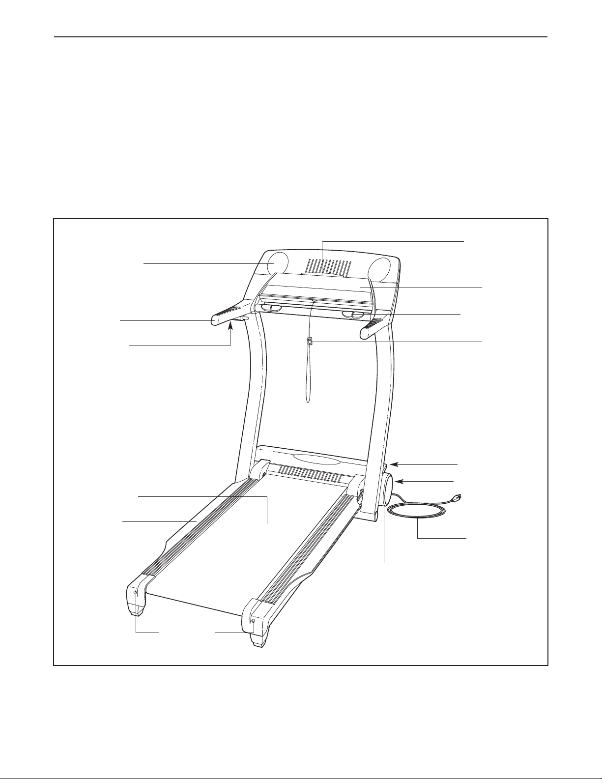
Water Bottle
Holder (Bottle
is not included)
Handrail
Lock Knob
Department toll-free at 1-800-999-3756, Monday
through Friday, 6 a.m. until 6 p.m. Mountain Time (ex-
luding holidays). To help us assist you, please note
c
the product model number and serial number before
calling. The model number of the treadmill is
RBTL69921. The serial number can be found on a
decal attached to the treadmill (see the front cover of
this manual for the location).
Before reading further, please review the drawing
below and familiarize yourself with the labeled parts.
Book Holder
Console
Pulse Sensor
Key/Clip
LEFT SIDE
Walking Belt
Foot Rail
RIGHT SIDE
On/Off Switch
Circuit Breaker
Power Cord
Front Wheel
Rear Roller
Adjustment Bolts
5
ASSEMBLY
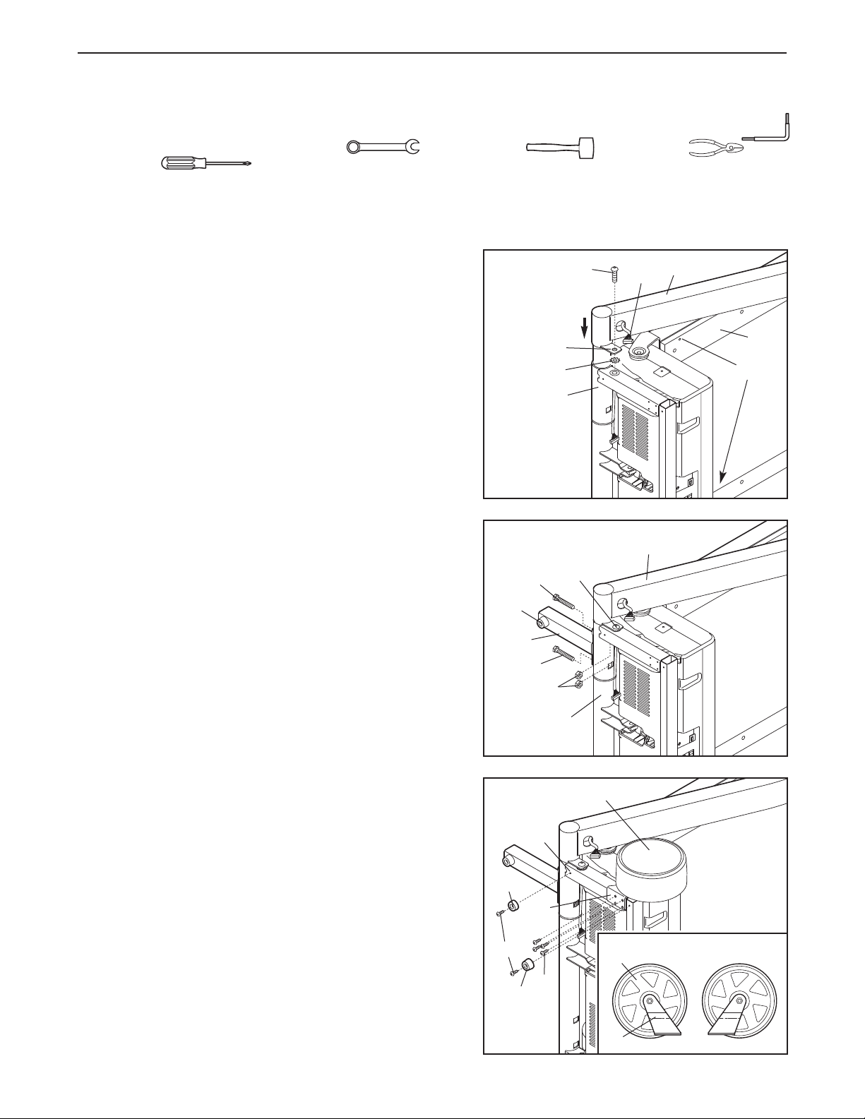
Assembly requires two people. Set the treadmill in a cleared area and remove the packing materials. Do not
ispose of the packing materials until assembly is completed. Assembly requires the included allen wrench
d
and your own 7/16” and 9/16” wrenches , rubber mallet , wire cutters ,
and Phillips screwdriver.
se the part chart attached in the center of this manual to identify small parts used in assembly. Each
U
bag of hardware is labeled with the corresponding assembly step.
1. With the help of another person, carefully tip the treadmill
onto its left side. Have the other person continue to hold
the treadmill during steps 1 through 4. Note: Only half of
the hardware in the bags for steps 1 to 3 will be used. The
remaining hardware will be used at the end of step 4.
Identify the Right Upright (58), which contains the Wire
Harness (55). Insert the round tube on the Right Upright into
the Base (117) as shown. If necessary, apply grease to
the round tube and use a rubber mallet. Hold a Star Washer
(113) between the indicated tab and the Base, and Finger
tighten an Upright Bolt (66) through the tab into the Base.
Make sure that the two indicated Walking Platform
Screws (114) in the Walking Platform (100) are tight.
2. Attach a Base Leg (78) to the Base (117) with two Base
Leg Bolts (77) and two Base Leg Nuts (70). Make sure
that the Base Pad (75) is in the position shown. (Note:
The Base Leg Nuts fit into square holes in the Base. If
necessary, push or pull on the Right Upright [58] to align
the holes.) Do not fully tighten the Base Leg Bolts yet.
1
2
77
75
78
66
Tab
113
117
66
55
58
100
114
58
3. See the inset drawing. Identify the right Front Wheel (62)
by observing the direction that the Wheel Bracket (64)
slants.
Attach the Wheel Bracket (64) and the right Front Wheel
(62) to the Base (117) with four 3/4” Screws (12) as
shown.
Attach a Thin Base Pad (103) and a Thick Base Pad (75)
to the Base (117) with two 3/4” Screws (12) as shown.
6
3
103
12
75
77
117
64
12
70
117
62
62
64
Right
Left
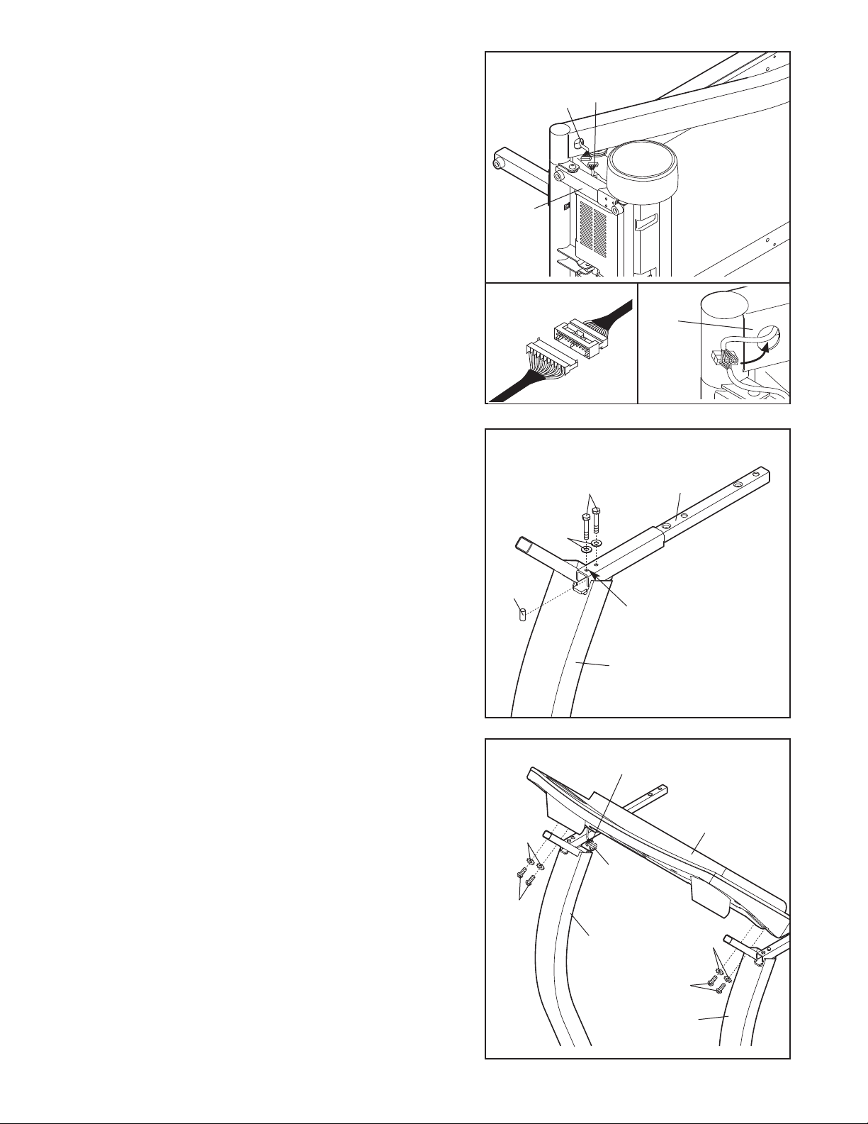
4. Locate the Belly Pan Wire Harness (124). Route the Belly
Pan Wire Harness over the Base (117) as shown.
Connect the Belly Pan Wire Harness to the Wire Harness
55). Be sure to insert the connectors properly (see
(
drawing 4a). IF THE CONNECTORS ARE NOT IN-
ERTED PROPERLY, THE CONSOLE MAY BE DAM-
S
AGED WHEN THE POWER IS TURNED ON. The connectors should slide together easily and snap into
place. If the connectors do not slide easily and snap into
place, turn a connector and try again.
See drawing 4b. Carefully wrap the wires around the connectors as shown. Insert the connectors and the excess
Wire Harness into the Right Upright (58).
With the help of another person, carefully tip the treadmill
onto its other side. Attach the Left Upright, the other Base
Leg, the left Front Wheel, and the other Base Pads (not
shown) as described in steps 1 through 3. (Note: There is
not a wire harness in the Left Upright.) Do not fully
tighten the bolts yet.
4
4a
117
55
124
4b
58
5. With the help of another person, carefully raise the
Uprights (35, 58) to the vertical position, with the wheels
and the walking platform on the floor as shown on page 5.
Have the other person hold a Handgrip Post (41) on the
Left Upright (35) as shown. Hold a Post Spacer (43) in-
side of the Handgrip Post. Insert a Post Bolt (44) with a
1/4” Washer (125) through the end hole in the Handgrip
Post and through the Post Spacer. Finger tighten the
Post Bolt. Finger tighten another Post Bolt (44) with a 1/4”
Washer (125) into the other hole. If necessary, tap the
Handgrip Post with a rubber mallet to make sure that it is
fully seated. Tighten the Post Bolt in the end hole.
Then, tighten the other Post Bolt.
Attach the other Handgrip Post (41) to the right Upright
(not shown) as described above.
6. Have another person hold the Console Base (52) near
the Uprights (35, 58). Locate the wire harness extending
from the Console Base. Connect the wire harness to the
Wire Harness (55) in the Right Upright. If the connectors
do not fit together easily, rotate them and then connect them. Carefully feed the connectors and the excess
wire harness into the Right Upright. Carefully set the
Console Base on the posts on the Uprights.
5
44
125
43
End
Hole
35
6
Wire Harness
113
55
41
52
Finger tighten four Console Bolts (42) with four Star
Washers (113) into the Uprights (35, 58) and the Console
Base (52). After all four Console Bolts have been started,
tighten them.
See step 1. Tighten the two Upright Bolts (66). See
step 2. Tighten the four Base Leg Bolts (77). Make
sure that the Base Leg Nuts (70) are fully seated in
the square holes. Note: It may be helpful to tip the
treadmill onto its side to tighten the Base Leg Bolts.
7
42
58
113
42
35
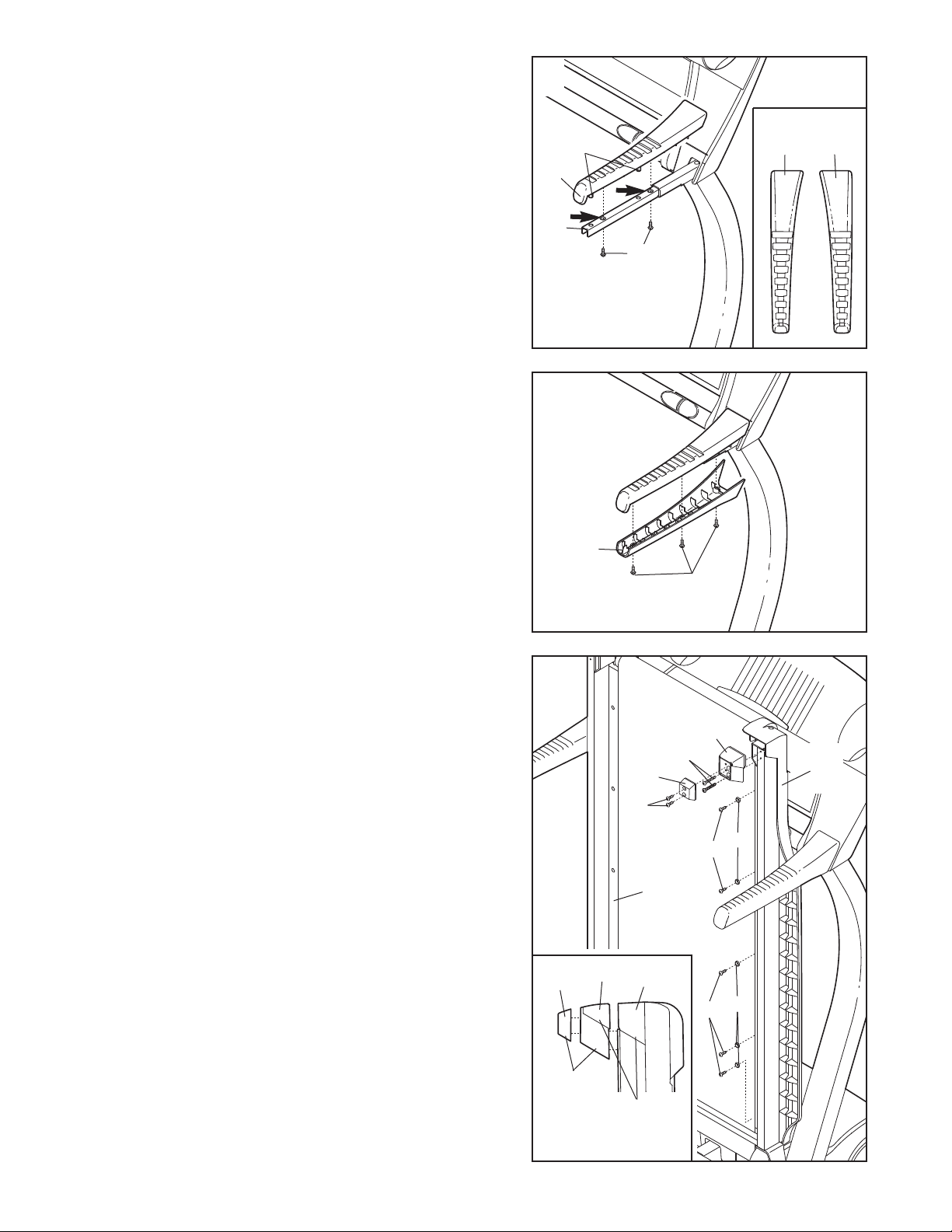
7. See the inset drawing. Identify the Right Top Handgrip
53); there are identifying marks inside the Handgrips.
(
Set the Right Top Handgrip on the right Handgrip Post
(41). Insert two 1/2” Screws (51) into the two holes in
the Handgrip Post indicated by the arrows. Tighten
the Screws into the Right Top Handgrip.
mportant: Be careful not to insert the two 1/2”
I
Screws (51) into the wrong holes in the Handgrip
Post (41), or tighten the Screws into the plastic
bosses on the bottom of the Right Top Handgrip (53).
7
B
53
41
osses
51
Left
21
Right
53
8. Attach the matching Right Bottom Handgrip (54) with
three 1/2” Screws (51).
Attach the Left Top Handgrip (21) and the Left Bottom
Handgrip (not shown) as described above.
9. Set the Right Foot Rail (98) and the Left Foot Rail (not
shown) on the sides of the Walking Platform (100). While
a second person holds the Foot Rails, raise the Walking
Platform to the position shown. Attach the Right Foot Rail
with five Foot Rail Screws (97) and five Foot Rail
Washers (96).
Attach the Left Foot Rail (not shown) in the same way.
Identify the Right Foot Housing (106) and one of the
Rubber Feet (104). See the inset drawing. Hold the Right
Foot Housing and the Rubber Foot near the upper end of
the Right Foot Rail (98) as shown. The ridge on the Right
Foot Housing should match the ridge on the Right Foot
Rail. In addition, the angle of the Rubber Foot should
match the angle of the Right Foot Housing. Make sure
that the parts are oriented exactly as shown. Attach the
Right Foot Housing with two Foot Housing Screws (105).
Attach the Rubber Foot with two Foot Screws (65).
Attach the Left Foot Housing (not shown) and the other
Rubber Foot (not shown) as described above.
Lower the Walking Platform (100) to the floor.
8
54
9
106
104
Matching
Angles
104
65
100
98
Ridges
105
51
106
97
97
98
96
96
Side View
8
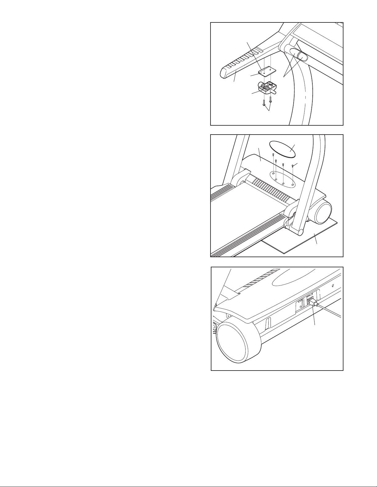
10.Attach the Latch Assembly (37) and the Latch Spacer
(39) to the Left Bottom Handgrip (40) with two Latch
Screws (36). Firmly tighten the Latch Screws. Note: The
idge on the Latch Spacer must be on the side shown.
r
f there are plastic ties around the left and right Pulse
I
Sensor Plates (2), cut off the plastic ties.
10
40
R
idge
9
3
37
2
36
11. Attach the Hood Cover (3) to the treadmill with four 1/2”
Screws (51). Firmly tighten the Screws.
Peel the backing off the Hood Decal (1). Position the
Hood Decal over the recess in the Hood Cover (3).
Press the Hood Decal into place.
Note: If the treadmill rocks slightly, tip the treadmill back
onto its side. See step 2. Loosen the four Base Leg Bolts
(77), adjust the positions of the Base Legs (78), and then
retighten the Base Leg Bolts. Raise the treadmill back to
the vertical position. Repeat until the rocking motion is
eliminated.
To protect the floor or carpet from damage, place the included Mat (129) under the front of the treadmill.
12. Plug the Power Cord (93) into the front of the treadmill as
shown.
Note: Extra parts may be included.
11
12
3
1
51
129
93
13. Make sure that all parts are properly tightened before you use the treadmill. Keep the included allen
wrench in a secure place. The allen wrench is used to adjust the walking belt (see pages 25 and 26). To protect the floor or carpet from damage, place a mat under the treadmill.
Note: The underside of the treadmill walking belt is coated with high-performance lubricant. During shipping,
a small amount of lubricant may be transferred to the top of the walking belt or the shipping carton. This is a
normal condition and does not affect treadmill performance. If there is lubricant on top of the walking belt,
simply wipe off the lubricant with a soft cloth and a mild, non-abrasive cleaner.
9
HOW TO USE THE CHEST PULSE SENSOR
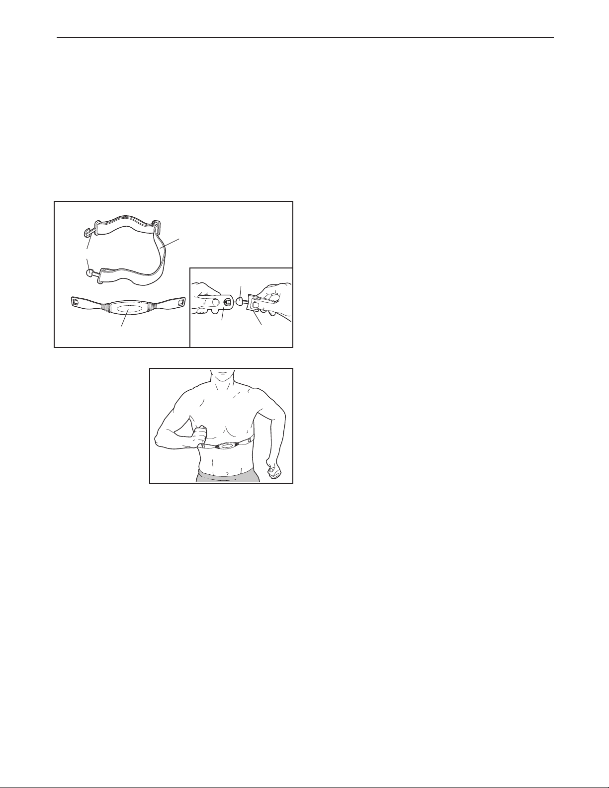
OW TO PUT ON THE CHEST PULSE SENSOR
H
The chest pulse sensor consists of two components:
the chest strap and the sensor unit (see the drawing
elow). Insert the tab on one end of the chest strap into
b
one end of the sensor unit, as shown in the inset drawing. Press the end of the sensor unit under the buckle
on the chest strap. The tab should be flush with the
front of the sensor unit.
ried. If the chest pulse sensor is not dried after
d
each use, it may remain activated longer than necessary, draining the battery prematurely.
Store the chest pulse sensor in a warm, dry place.
•
Do not store the chest pulse sensor in a plastic bag
or other container that may trap moisture.
• Do not expose the chest pulse sensor to direct
sunlight for extended periods of time; do not expose
it to temperatures above 122° Fahrenheit (50°
Celsius) or below 14° Fahrenheit (-10° Celsius).
Chest Strap
Tabs
Tab
Sensor Unit
Next, wrap the
chest pulse sensor around your
chest and attach
the other end of
the chest strap to
the sensor unit.
Adjust the length
of the chest strap,
if necessary. The
chest pulse sensor should be under your clothes, tight against your
skin, and as high under the pectoral muscles or
breasts as is comfortable. Make sure that the logo on
the sensor unit is facing forward and is right-side-up.
Pull the sensor unit away from your body a few inches
and locate the two electrode areas on the inner side
(the electrode areas are covered by shallow ridges).
Using saline solution such as saliva or contact lens solution, wet both electrode areas. Return the sensor unit
to a position against your chest.
Sensor
Unit
Buckle
• Do not excessively bend or stretch the sensor unit
when using or storing the chest pulse sensor.
• Clean the sensor unit using a damp cloth—never
use alcohol, abrasives, or chemicals. The chest
strap may be hand washed and air dried.
CHEST PULSE SENSOR TROUBLESHOOTING
The instructions on the following pages explain
how the chest pulse sensor is used with the console. If the chest pulse sensor does not function
properly, try the steps below.
• Make sure that you are wearing the chest pulse sensor as described at the left. Note: If the chest pulse
sensor does not function when positioned as described, move it slightly lower or higher.
• Use saline solution such as saliva or contact lens
solution to wet the two electrode areas on the
sensor unit. If heart rate readings do not appear until
you begin perspiring, re-wet the electrode areas.
• As you walk or run on the treadmill, position yourself near the center of the walking belt. For the
console to display heart rate readings, the user
must be within armʼs length of the console.
• The chest pulse sensor is designed to work with
people who have normal heart rhythms. Heart rate
reading problems may be caused by medical
conditions such as premature ventricular contractions (pvcs), tachycardia bursts, and arrhythmia.
CHEST PULSE SENSOR CARE AND MAINTENANCE
• Thoroughly dry the chest pulse sensor after each
use. The chest pulse sensor is activated when the
electrode areas are wetted and the heart rate
monitor is put on; the chest pulse sensor shuts off
when it is removed and the electrode areas are
• The operation of the chest pulse sensor can be
affected by magnetic interference caused by high
power lines or other sources. If it is suspected that
this is a problem, try relocating the treadmill.
• The CR2032 battery may need to be replaced (see
page 26).
10
 Loading...