

Reebok RBEX49840 User Manual
Model No. RBEX49840
Visit our website at
www.reebokhomefitness.com
new products, prizes,
fitness tips, and much more!
Serial No.
Serial
Number
Decal
QUESTIONS?
As a manufacturer, we are committed to providing complete
customer satisfaction. If you
have questions, or if there are
missing parts, we will guarantee
complete satisfaction through
direct assistance from our factory.
TO AVOID DELAYS, PLEASE
CALL DIRECT T
FREE CUSTOMER HOT LINE.
The trained technicians on our
customer hot line will provide
immediate assistance, free of
charge to you.
O OUR TOLL-
USER'S MANUAL
CUSTOMER HOT LINE:
1-877-994-4999
Mon.–Fri., 6 a.m.–6 p.m. MST
CAUTION
Read all precautions and instructions in this manual before using
this equipment. Keep this manual
for future reference.
atent Pending
P
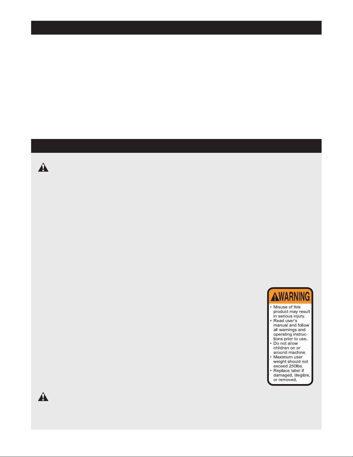
TABLE OF CONTENTS
IMPOR
BEFORE YOU BEGIN . . . . . . . . . . . . . . . . . . . . . . . . . . . . . . . . . . . . . . . . . . . . . . . . . . . . . . . . . . . . . . . . . . . . . .3
ASSEMBL
EXERCISE CYCLE OPERATION . . . . . . . . . . . . . . . . . . . . . . . . . . . . . . . . . . . . . . . . . . . . . . . . . . . . . . . . . . . . . .8
MAINTENANCE AND TROUBLESHOOTING . . . . . . . . . . . . . . . . . . . . . . . . . . . . . . . . . . . . . . . . . . . . . . . . . . .20
EXERCISE GUIDELINES . . . . . . . . . . . . . . . . . . . . . . . . . . . . . . . . . . . . . . . . . . . . . . . . . . . . . . . . . . . . . . . . . . .21
PART LIST . . . . . . . . . . . . . . . . . . . . . . . . . . . . . . . . . . . . . . . . . . . . . . . . . . . . . . . . . . . . . . . . . . . . . . . . . . . . . .22
EXPLODED DRAWING . . . . . . . . . . . . . . . . . . . . . . . . . . . . . . . . . . . . . . . . . . . . . . . . . . . . . . . . . . . . . . . . . . . .23
ORDERING REPLACEMENT PARTS . . . . . . . . . . . . . . . . . . . . . . . . . . . . . . . . . . . . . . . . . . . . . . . . . .Back Cover
LIMITED WARRANTY . . . . . . . . . . . . . . . . . . . . . . . . . . . . . . . . . . . . . . . . . . . . . . . . . . . . . . . . . . . . . .Back Cover
TANT PRECAUTIONS . . . . . . . . . . . . . . . . . . . . . . . . . . . . . . . . . . . . . . . . . . . . . . . . . . . . . . . . . . . . . . . .2
Y . . . . . . . . . . . . . . . . . . . . . . . . . . . . . . . . . . . . . . . . . . . . . . . . . . . . . . . . . . . . . . . . . . . . . . . . . . . . . . .4
IMPORTANT PRECAUTIONS
WARNING: To reduce the risk of serious injury, read the following important precau-
tions before using the exercise cycle.
1. Read all instructions in this manual before
using the exercise cycle.
2. Use the exercise cycle only as described in
this manual.
3. It is the responsibility of the owner to ensure
that all users of the exercise cycle are adequately informed of all precautions.
4. The exercise cycle is intended for in-home
use only. Do not use the exercise cycle in a
commercial, rental, or institutional setting.
5. Use the exercise cycle indoors on a level
surface. Keep the exercise cycle away from
moisture and dust. Place a mat under the
exercise cycle to protect the floor or carpet.
6. Inspect and properly tighten all parts regularly. Replace any worn parts immediately.
7. Keep children under the age of 12 and pets
away from the exercise cycle at all times.
The exercise cycle should not be used by
8.
persons weighing more than 250 pounds.
9. Always keep your back straight when using
the exercise cycle. Do not arch your back.
10. Wear appropriate clothes when exercising;
do not wear loose clothes that could become
caught on the exercise cycle. Always wear
athletic shoes.
11. The pulse sensor is not a medical device.
Various factors, including the user's movement, may affect the accuracy of heart rate
readings. The pulse sensor is intended only
as an exercise aid in determining heart rate
trends in general.
12. If you feel pain or dizziness while exercising,
stop immediately and cool down.
The decal shown at the
13.
right has been
the exercise cycle in the
location shown on page 3.
If the decal is missing or
illegible, call toll-free
1-877-994-4999, Monday
through Friday, 6 a.m.
until 6 p.m. Mountain
Time, and order a free
replacement decal. Apply
the replacement decal in
the location shown.
placed on
WARNING: Before beginning this or any exercise program, consult your physician.
This is especially important for persons over the age of 35 or persons with pre-existing health problems. Read all instructions before using. ICON assumes no responsibility for personal injury or
property damage sustained by or through the use of this product.
2
BEFORE YOU BEGIN
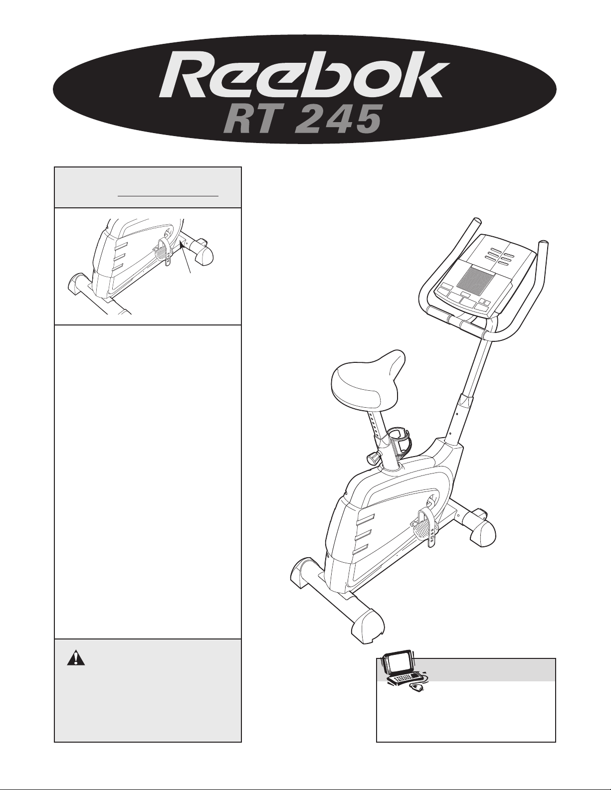
Congratulations for selecting the new REEBOK®RT
245 exercise cycle. Cycling is one of the most effective exercises for increasing cardiovascular fitness,
building
R
features designed to let you enjoy this healthful exercise in the comfort and privacy of your home.
For your benefit, read this manual carefully before
you use the exercise cycle. If you have questions
after reading this manual, please call our Customer
endurance, and toning the entire body. The
T 245 exercise cycle offers an impressive array of
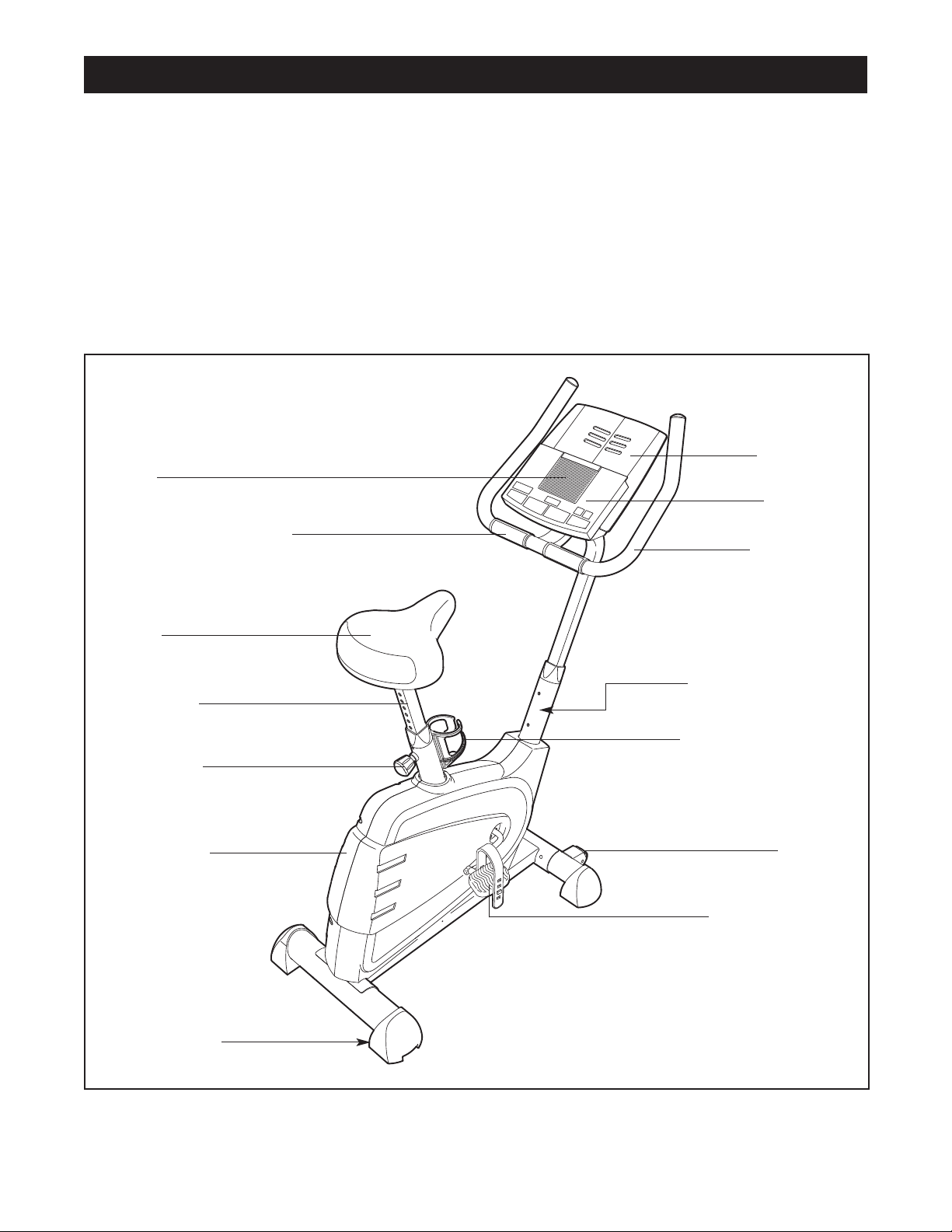
Fan
Handgrip Pulse Sensor
Service Department toll-free at 1-877-994-4999,
Monday through Friday, 6 a.m. until 6 p.m. Mountain
Time (excluding holidays). To help us assist you,
please mention the product model number and serial
number when calling.
RBEX49840. The serial number can be found on a
decal attached to the exercise cycle (see the front
cover of this manual for the location of the decal).
Before reading further, please familiarize yourself with
the parts that are labeled in the drawing below.
The model number is
Bookrack
Console
Handlebar
Seat
Seat Post
Seat Knob
Side Shield
BACK
Leveling Pad
FRONT
WARNING DECAL
Water Bottle Holder*
Wheel
Pedal with Strap
RIGHT SIDE
*No water bottle is included
3
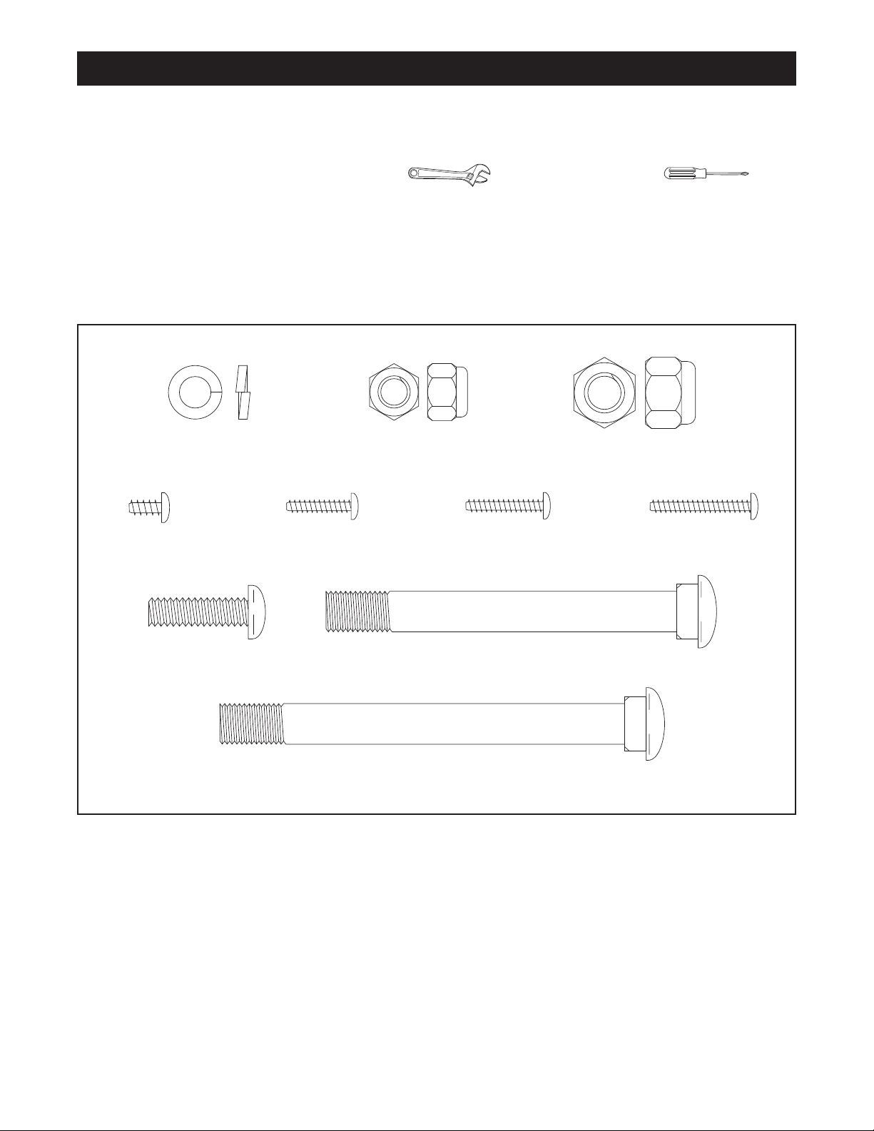
M8 x 25mm Button
Screw (19)–7
M10 x 92mm Carriage Bolt (62)–2
M10 x 105mm Carriage Bolt (64)–2
M6 x 8mm
Screw (26)–2
M8 Split Washer
(28)–11
M4 x 16mm
Screw (21)–4
M4 x 25mm
Screw (20)–2
M10 Nylon
Locknut (48)–4
M8 Nylon
Locknut (56)–4
M4 x 19mm
Screw (59)–2
ASSEMBLY
Place all parts of the exercise cycle in a cleared area and remove the packing materials. Do not dispose of the
packing materials until assembly is completed.
Assembly requires your own adjustable wrench and phillips screwdriver .
ART CHART
P
Use the part drawings below to identify the small parts used in assembly. The number in parenthesis below
each drawing refers to the key number of the part, from the PART LIST on page 22. The second number refers
to the quantity used in assembly.
part is not in the parts bag, check to see if it has been pre-assembled.
Note: Some small parts may have been pre-assembled for shipping. If a
4
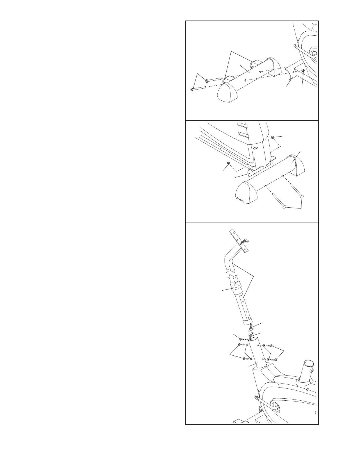
1. Identify the Front Stabilizer (2), which has Wheels
(17) attached to one side.
to the Frame (1) with two M10 x 92mm Carriage
Bolts (62) and two M10 Nylon Locknuts (48).
Attach the Front Stabilizer
1
17
2
62
1
48
2. Attach the Rear Stabilizer (3) to the Frame (1) with
two M10 x 105mm Carriage Bolts (64) and two M10
Nylon Locknuts (48).
3. While another person holds the Handlebar Post (6)
near the Frame (1), connect the Upper Wire
Harness (16) to the Lower Wire Harness (24). Next,
pull the excess Upper Wire Harness out of the top of
the Handlebar Post, and insert the Handlebar Post
into the Frame. Be careful not to pinch the Wire
Harnesses.
Slide the Round Collar (13) down the Handlebar
Post (6) and press it into the Frame (1). Attach the
Round Collar with an M6 x 8mm Screw (26).
2
48
3
48
1
64
3
6
13
Note: There are two sets of holes in the
Handlebar Post (6) so that it can be attached at
either of two heights. Attach the Handlebar Post to
the Frame (1) at the desired height with four M8 x
25mm Button Screws (19) and four M8 Split
Washers (28).
16
19
26
28
24
19
28
1
5
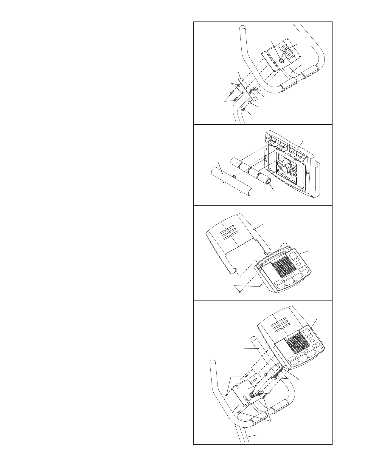
4. While another person holds the Handlebar (7) near
the Handlebar Post (6), feed the Upper Wire
Harness (16) and the Pulse Sensor W
through the indicated hole in the Handlebar. Attach
the Handlebar to the Handlebar Post with three M8
x 25mm Button Screws (19) and three M8 Split
Washers (28).
ire (45) up
4
Hole
6
28
45
7
5. The Console (9) requires four “D” batteries (not
included); alkaline batteries are recommended.
Press the indicated tab on the battery cover and
remove the cover. Press four batteries into the battery clips;
ed as shown by the markings inside of the bat
tery clips. Then, reattach the battery cover.
6. Insert the Bookrack (8) into the slots in the Console
(9). Attach the Bookrack to the Console with two M4
x 25mm Screws (20). Be careful not to pinch the
wires in the Console.
make sure that the batteries are orient
19
5
-
-
Battery
Cover
6
16
28
19
9
Batteries
8
9
7. While another person holds the Console (9) near
the Handlebar (7), connect the Pulse Sensor Wire
(45) and the Upper W
sponding wires on the Console.
Insert all excess wiring down into the Handlebar
Post (6). Attach the Console (9) to the Handlebar
(7) with four M4 x 16mm Screws (21). Be careful
not to pinch the Pulse Sensor W
Upper Wire Harness (16).
ire Harness (16) to the corre
ires (45) or the
20
7
-
7
21
45
16
21
6
9
Console
Wires
6
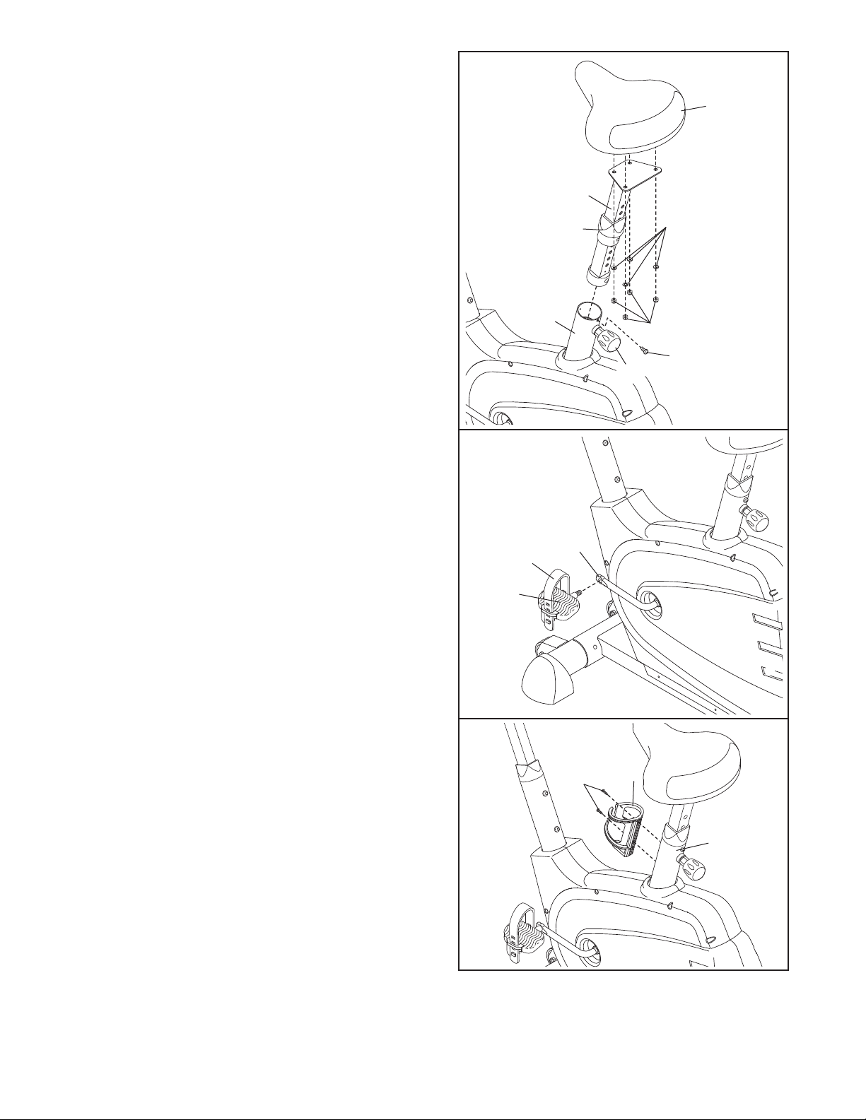
8. Attach the Seat (12) to the Seat Post (11) with four
M8 Nylon Locknuts (56) and four M8 Split Washers
Note: The Nylon Locknuts and Split
(28).
Washers may be pre-attached to the Seat.
Turn the Seat Knob (31) counterclockwise two or
three turns to loosen it. Next, pull the Knob, insert
the Seat Post (11) into the Frame (1), and then
release the Knob. Slide the Round Collar (13) down
the Seat Post and press it into the Frame. Attach
the Round Collar to the Frame with an M6 x 8mm
Screw (26). Move the Seat Post up and down
slightly until the pin on the Knob snaps into one
of the holes in the Seat Post. Then, turn the Knob
clockwise until it is tight.
8
12
11
13
28
9. Identify the Left Pedal (40); the threaded shaft on
each Pedal is marked with an “L” for “left” or an “R”
for “right.” Using an adjustable wrench, firmly tight-
en the Left Pedal counterclockwise into the Crank
Assembly (33). Tighten the Right Pedal (not shown)
clockwise into the Crank Assembly. Important:
Tighten both Pedals as firmly as possible. After
using the exercise cycle for one week, retighten
the Pedals. For best performance, the Pedals
must be kept tightened.
Identify the Left Pedal Strap (41), which is marked
with an “L.” Attach the Left Pedal Strap to the Left
Pedal (40), and adjust the Left Pedal Strap to the
desired position. Attach and adjust the Right Pedal
Strap (not shown) in the same way.
Attach the W
10.
with two M4 x 19mm Screws (59).
bottle holder is designed to be used with your own
water bottle.
ater Bottle Holder (63) to the Frame (1)
The water
Note:
9
10
40
41
1
33
59
56
26
31
63
1
11.Make sure that all parts are properly tightened before you use the exercise cycle. Note: Some hard
ware may be left over after assembly is completed. Place a mat under the exercise cycle to protect the
floor or carpet.
7
-
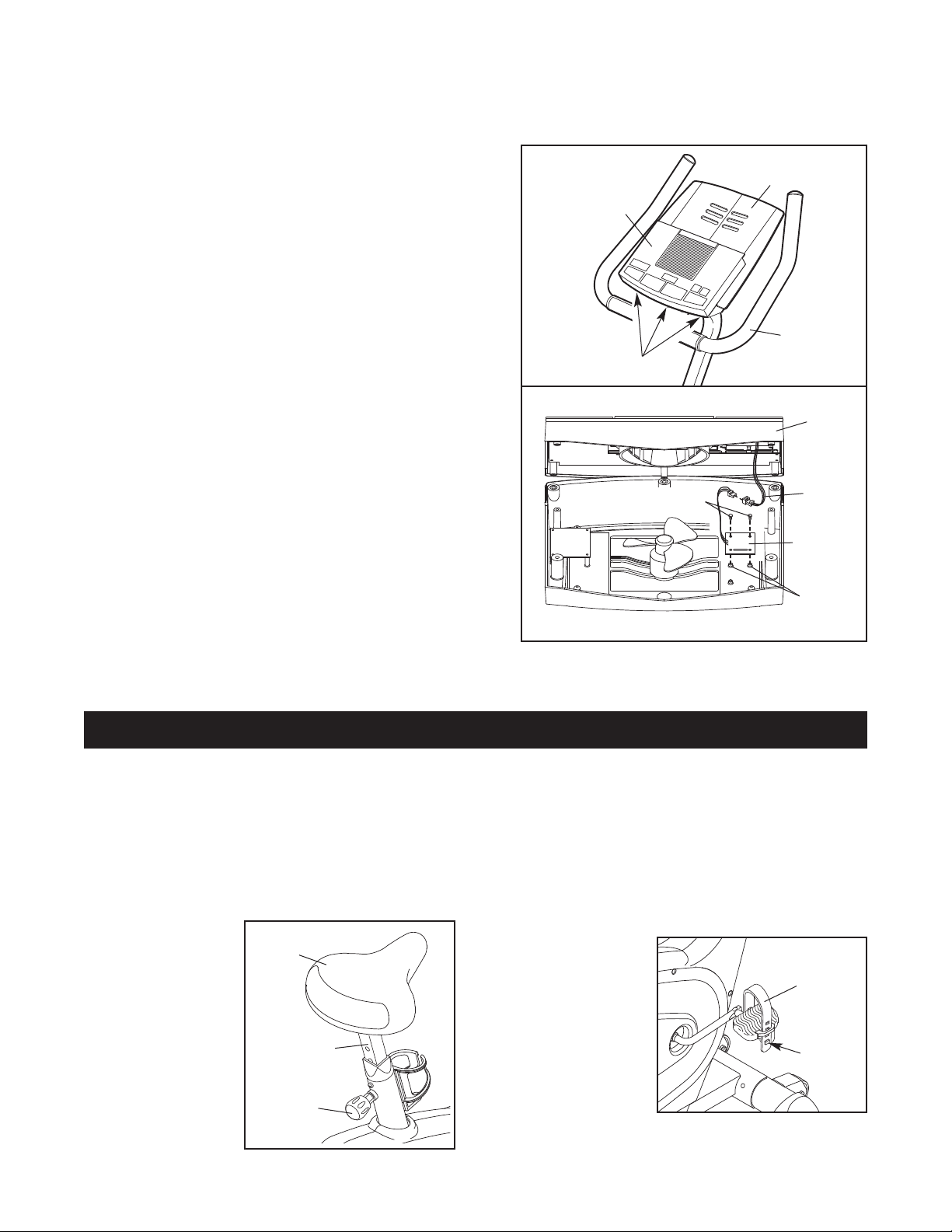
HOW TO INSTALL THE RECEIVER FOR THE OPTIONAL CHEST PULSE SENSOR
If you purchase the optional chest pulse sensor (see page
included with the chest pulse sensor.
1. See assembly step 5 on page 6, and remove the two
M4 x 25mm Screws (not shown) and the Bookrack (8).
Next, look under the console and locate the three indicated screws (not shown). Remove the three screws.
Do not remove the screws attaching the Console to
the Handlebar (7).
2. Carefully lift the top of the Console (9) as shown. Using
the two small screws included with the chest pulse sensor, attach the receiver to the indicated plastic posts on
the Console. Make sure that the receiver is turned
exactly as shown. Connect the wire on the receiver to
the indicated wire on the Console.
See step 1 above. Lower the top of the Console (9).
Make sure that no wires are pinched. Reattach the
top of the Console with the three screws removed in
step 1. See assembly step 5 on page 6, and reattach
the Bookrack (8) with the two M4 x 25mm Screws (not
shown). Note: The remaining wires included with the
chest pulse sensor may be discarded.
19), follow the steps below to install the receiver
1
8
9
7
Screws
2
Screws
Wire
Receiver
Posts
9
EXERCISE CYCLE OPERATION
ADJUST THE HEIGHT OF THE SEA
HOW T
For effective exercise, the seat should be at the proper
height. As you pedal, there should be a slight bend in
your knees when the pedals are in the lowest position.
To adjust the seat, first turn the seat knob counterclockwise several
turns to loosen it.
Next, pull the knob,
slide the seat post
up or down as
desired, and then
release the knob.
Move the seat
post up or down
slightly to make
sure that it locks
into place. Turn
the knob clockwise
to retighten it.
O
Seat
Seat Post
Seat
Knob
T
ADJUST THE HANDLEBARS
HOW T
The handlebars can be adjusted to either of two
heights. To adjust the handlebars, see assembly step
3 on page 5.
HOW TO ADJUST THE PEDAL STRAPS
To adjust the pedal
straps, first pull the
ends of the straps
off the tabs on the
pedals. Press the
straps back onto
the tabs using different holes in the
straps.
O
Strap
Ta b
8
 Loading...