

Reebok RBEX11911.1 User Manual
www.reebokfitness.com
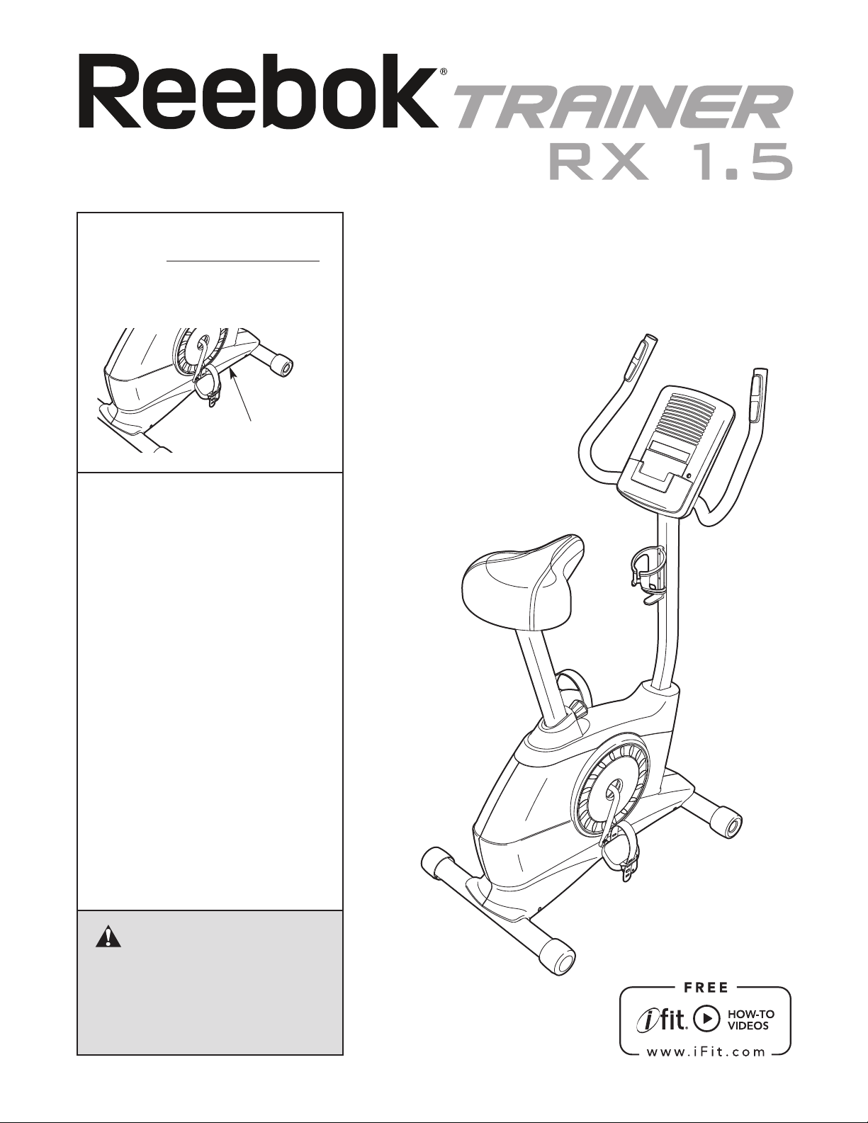
Model No. RBEX11911.1
Serial No.
Write the serial number in the
space above for reference.
Serial Number Decal
(under frame)
QUESTIONS?
If you have questions, or if parts are
damaged or missing, DO NOT
CONTACT THE STORE; please
contact Customer Care.
USER'S MANUAL
IMPORTANT: Please register this
product (see the limited warranty
on the back cover of this manual)
before contacting Customer Care.
CALL TOLL-FREE:
1-877-994-4999
Mon.–Fri. 6 a.m.–6 p.m. MT
Sat. 8 a.m.–4 p.m. MT
ON THE WEB:
www.reebokservice.com
CAUTION
Read all precautions and instructions in this manual before using
this equipment. Keep this manual
for future reference.
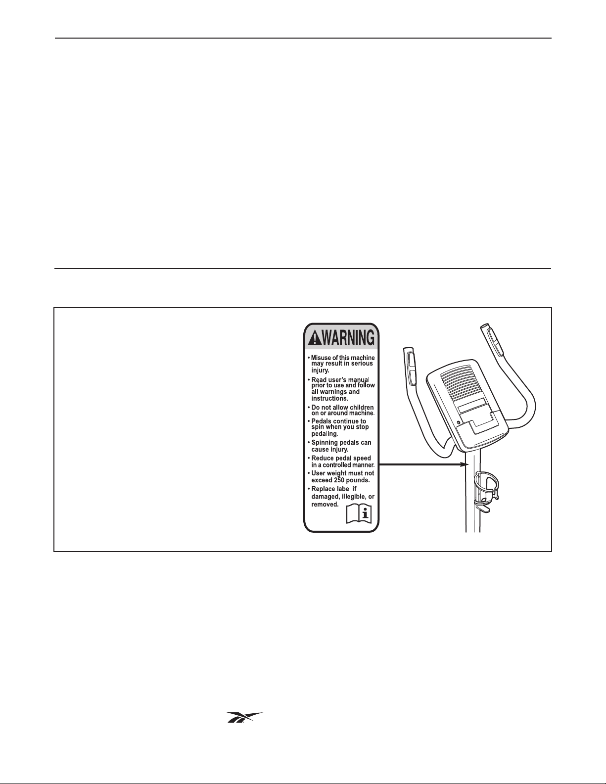
TABLE OF CONTENTS
WARNING DECAL PLACEMENT . . . . . . . . . . . . . . . . . . . . . . . . . . . . . . . . . . . . . . . . . . . . . . . . . . . . . . . . . . . . . .2
IMPORTANT PRECAUTIONS . . . . . . . . . . . . . . . . . . . . . . . . . . . . . . . . . . . . . . . . . . . . . . . . . . . . . . . . . . . . . . . .3
BEFORE YOU BEGIN . . . . . . . . . . . . . . . . . . . . . . . . . . . . . . . . . . . . . . . . . . . . . . . . . . . . . . . . . . . . . . . . . . . . . .4
ASSEMBLY . . . . . . . . . . . . . . . . . . . . . . . . . . . . . . . . . . . . . . . . . . . . . . . . . . . . . . . . . . . . . . . . . . . . . . . . . . . . . . .5
OW TO USE THE EXERCISE BIKE . . . . . . . . . . . . . . . . . . . . . . . . . . . . . . . . . . . . . . . . . . . . . . . . . . . . . . . . .12
H
FCC INFORMATION . . . . . . . . . . . . . . . . . . . . . . . . . . . . . . . . . . . . . . . . . . . . . . . . . . . . . . . . . . . . . . . . . . . . . . .17
MAINTENANCE AND TROUBLESHOOTING . . . . . . . . . . . . . . . . . . . . . . . . . . . . . . . . . . . . . . . . . . . . . . . . . . .18
EXERCISE GUIDELINES . . . . . . . . . . . . . . . . . . . . . . . . . . . . . . . . . . . . . . . . . . . . . . . . . . . . . . . . . . . . . . . . . . .20
PART LIST . . . . . . . . . . . . . . . . . . . . . . . . . . . . . . . . . . . . . . . . . . . . . . . . . . . . . . . . . . . . . . . . . . . . . . . . . . . . . .22
EXPLODED DRAWING . . . . . . . . . . . . . . . . . . . . . . . . . . . . . . . . . . . . . . . . . . . . . . . . . . . . . . . . . . . . . . . . . . . .23
ORDERING REPLACEMENT PARTS . . . . . . . . . . . . . . . . . . . . . . . . . . . . . . . . . . . . . . . . . . . . . . . . . .Back Cover
LIMITED WARRANTY . . . . . . . . . . . . . . . . . . . . . . . . . . . . . . . . . . . . . . . . . . . . . . . . . . . . . . . . . . . . . .Back Cover
WARNING DECAL PLACEMENT
This drawing shows the location(s) of the
warning decal(s). If a decal is missing or
illegible, see the front cover of this
manual and request a free replacement
decal. Apply the decal in the location
shown. Note: The decal(s) may not be
shown at actual size.
REEBOK and the Vector Logo are registered trademarks and service marks of Reebok.
This product is manufactured and distributed under license from Reebok International.
2

IMPORTANT PRECAUTIONS
WARNING: T
instructions in this manual and all warnings on your exercise bike before using your exercise bike.
ICON assumes no responsibility for personal injury or property damage sustained by or through the
use of this product.
1. Before beginning any exercise program,
consult your physician. This is especially
important for persons over age 35 or persons with pre-existing health problems.
2. Use the exercise bike only as described in
this manual.
3. It is the responsibility of the owner to ensure
that all users of the exercise bike are adequately informed of all precautions.
4. The exercise bike is intended for home use
only. Do not use the exercise bike in a commercial, rental, or institutional setting.
5. Keep the exercise bike indoors, away from
moisture and dust. Do not put the exercise
bike in a garage or covered patio, or near
water.
o reduce the risk of serious injury, read all important precautions and
9. Wear appropriate clothes while exercising;
do not wear loose clothes that could become
caught on the exercise bike. Always wear
athletic shoes for foot protection.
10. The exercise bike should not be used by
persons weighing more than 250 lbs.
(113 kg).
11. The heart rate monitor is not a medical
device. Various factors, including the user's
movement, may affect the accuracy of heart
rate readings. The heart rate monitor is
intended only as an exercise aid in determining heart rate trends in general.
12. The exercise bike does not have a free
wheel; the pedals will continue to move until
the flywheel stops. Reduce your pedaling
speed in a controlled way.
6. Place the exercise bike on a level surface
with at least 2 ft. (0.6 m) of clearance around
the exercise bike. To protect the floor or
carpet from damage, place a mat under the
exercise bike.
7. Inspect and properly tighten all parts regularly. Replace any worn parts immediately.
8. Keep children under age 12 and pets away
from the exercise bike at all times.
13. Always keep your back straight while using
the exercise bike; do not arch your back.
14. Over exercising may result in serious injury
or death. If you feel faint or if you experience
pain while exercising, stop immediately and
cool down.
3
BEFORE YOU BEGIN
hank you for selecting the new REEBOK
T
RX 1.5 exercise bike. Cycling is an effective exercise
for increasing cardiovascular fitness, building
endurance, and toning the body. The TRAINER RX
.5 exercise bike provides an impressive selection of
1
features designed to make your workouts at home
more effective and enjoyable.
For your benefit, read this manual carefully before
you use the exercise bike. If you have questions
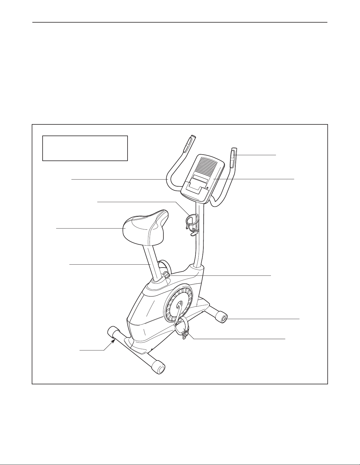
Length: 2 ft. 8 in. (81 cm)
Width: 2 ft. (61 cm)
Handlebar
Water Bottle Holder*
®
RAINER
T
fter reading this manual, please see the front cover
a
of this manual. To help us assist you, note the product
model number and serial number before contacting
us. The model number and the location of the serial
umber decal are shown on the front cover of this
n
manual.
Before reading further, please familiarize yourself with
the parts that are labeled in the drawing below.
Handgrip Heart
Rate Monitor
Console
Seat
Seat Post
Leveling Foot
Adjustment Knob
Wheel
Pedal/Strap
*Water bottle is not included
4
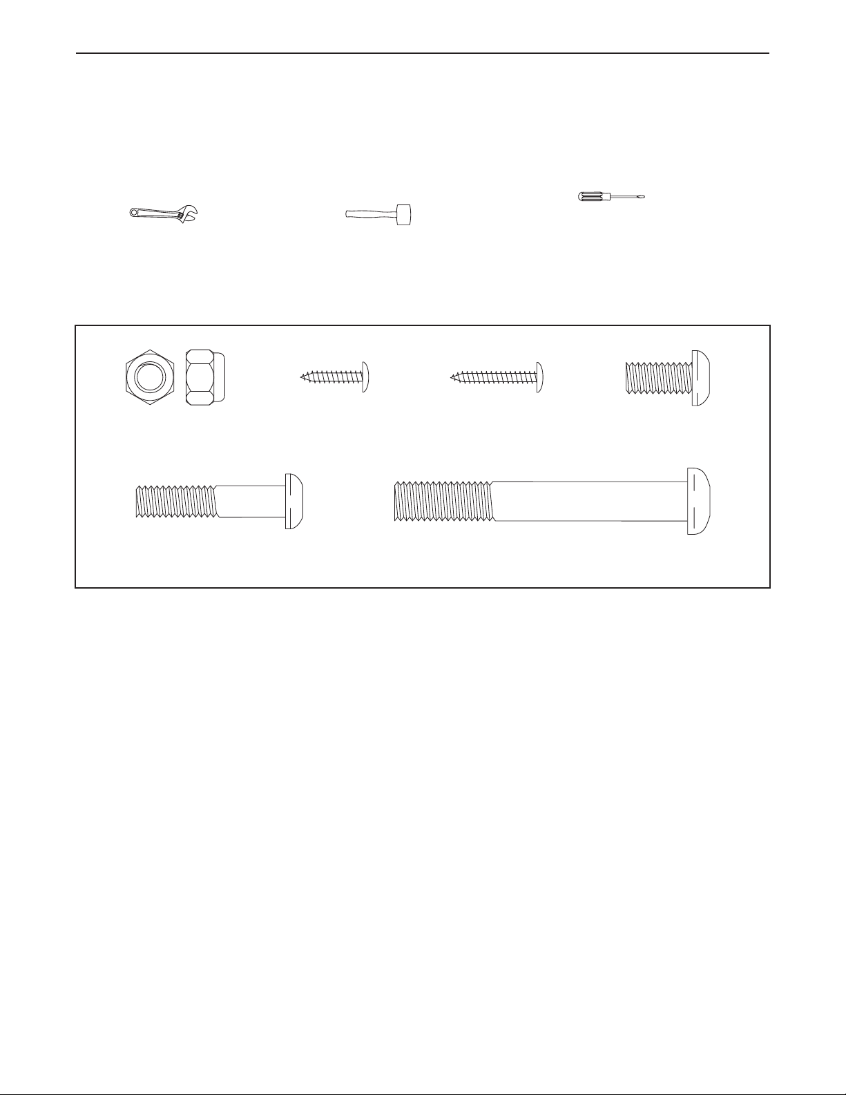
M8 Locknut
(37)–8
M4 x 22mm
Screw (54)–2
M4 x 16mm
Screw (40)–6
M10 x 75mm
Screw (36)–4
M8 x 38mm Button
Bolt (53)–4
M8 x 18mm
Screw (35)–4
ASSEMBLY
To hire an authorized service technician to assemble the exercise bike, call 1-800-445-2480.
Assembly requires two persons. Place all parts of the exercise bike in a cleared area and remove the packing
materials. Do not dispose of the packing materials until assembly is completed.
n addition to the included tool(s), assembly requires a Phillips screwdriver , an adjustable
I
wrench , and a rubber mallet .
Use the drawings below to identify the small parts needed for assembly. The number in parentheses below each
drawing is the key number of the part, from the PART LIST near the end of this manual. The number following
the key number is the quantity needed for assembly. Note: If a part is not in the hardware kit, check to see if
it has been preassembled. To avoid damaging parts, do not use power tools for assembly.
5
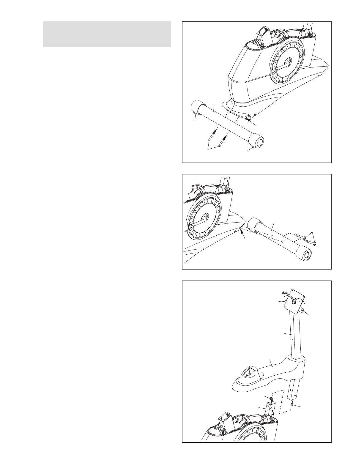
1.
To make assembly easier, read the
nformation on page 5 before you begin.
i
Identify the Rear Stabilizer (14), which has a
Leveling Foot (63) near each end.
Attach the Rear Stabilizer (14) to the Frame (1)
with two M10 x 75mm Screws (36).
1
14
2. Attach the Front Stabilizer (2) to the Frame (1)
with two M10 x 75mm Screws (36).
3. Orient the Upright (3) and the Top Shield (9) as
shown.
63
36
2
3
1
63
2
36
1
Have a second person hold the Upright (3) and
the Top Shield (9) near the Frame (1) until you
complete step 4.
Connect the Upper Wire (32) to the Lower Wire
(31). Then, pull the excess Upper Wire out of
the top of the Upright.
3
9
31
1
32
6
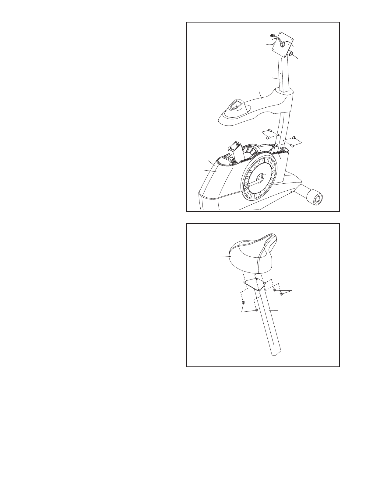
4. Tip: Avoid pinching the wires. Slide the
Upright (3) onto the Frame (1).
ttach the Upright (3) with four M8 x 18mm
A
Screws (35).
Slide the Top Shield (9) downward and press it
onto the Left and Right Shields (17, 18).
4
Avoid pinching
the wires
3
9
35
35
5. Attach the Seat (12) to the Seat Post (5) with
four M8 Locknuts (37). Note: The Locknuts
may be preattached to the underside of the
Seat.
17
18
5
12
37
1
37
5
7
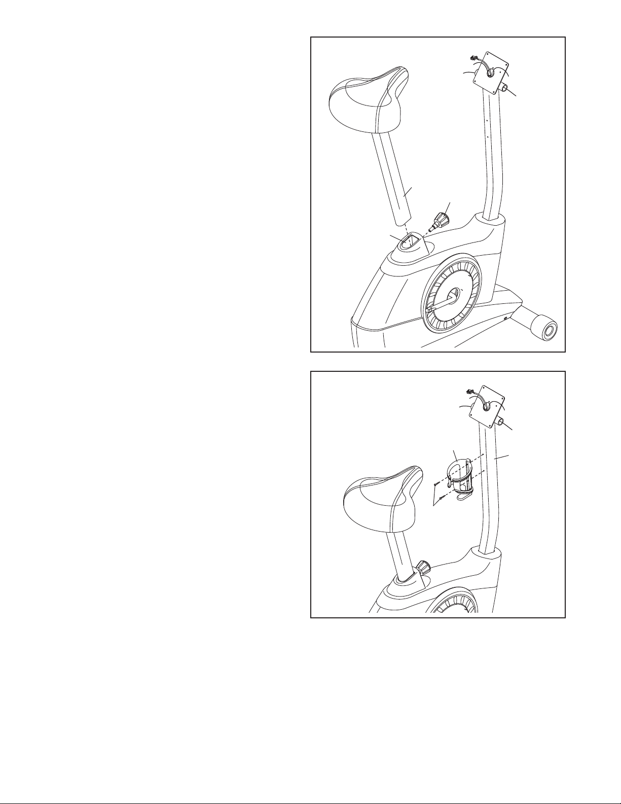
6. Using an adjustable wrench, tighten the
Adjustment Knob (11) into the Frame (1).
ext, loosen the Adjustment Knob (11) a few
N
turns, pull it outward, and insert the Seat Post
5) into the Frame (1).
(
Slide the Seat Post (5) upward or downward to
the desired position, and release the Adjustment
Knob (11) into one of the adjustment holes in
the Seat Post. Move the Seat Post upward or
downward slightly to make sure that the
Adjustment Knob is engaged in one of the
adjustment holes in the Seat Post. Then,
tighten the Adjustment Knob.
6
5
11
1
7. Attach the Water Bottle Holder (49) to the
Upright (3) with two M4 x 22mm Screws (54).
7
49
3
54
8
 Loading...