

Reebok RBEL99020 Owner's Manual
USER'S MANUAL
CAUTION
Read all precautions and instructions in this manual before using
this equipment. Keep this manual
for future reference.
QUESTIONS?
As a manufacturer, we are committed to providing complete
customer satisfaction. If you
have questions, or if there are
missing parts, we will guarantee
complete satisfaction through
direct assistance from our factory.
TO AVOID DELAYS, PLEASE
CALL DIRECT TO OUR TOLLFREE CUSTOMER HOT LINE.
The trained technicians on our
customer hot line will provide
immediate assistance, free of
charge to you.
CUSTOMER HOT LINE:
1-800-999-3756
Mon.–Fri., 6 a.m.–6 p.m. MST
Model No. RBEL99020
Serial No.
Serial Number
Decal (on top
of the frame)
Patent Pending
Visit our website at
www.reebokhomefitness.com
new products, prizes,
fitness tips, and much more!

2
IMPORTANT PRECAUTIONS . . . . . . . . . . . . . . . . . . . . . . . . . . . . . . . . . . . . . . . . . . . . . . . . . . . . . . . . . . . . .3
BEFORE YOU BEGIN . . . . . . . . . . . . . . . . . . . . . . . . . . . . . . . . . . . . . . . . . . . . . . . . . . . . . . . . . . . . . . . . . . .4
ASSEMBLY . . . . . . . . . . . . . . . . . . . . . . . . . . . . . . . . . . . . . . . . . . . . . . . . . . . . . . . . . . . . . . . . . . . . . . . . . . .5
HOW TO USE THE CHEST PULSE SENSOR . . . . . . . . . . . . . . . . . . . . . . . . . . . . . . . . . . . . . . . . . . . . . . . .10
ELLIPTICAL EXERCISER OPERATION . . . . . . . . . . . . . . . . . . . . . . . . . . . . . . . . . . . . . . . . . . . . . . . . . . . . .12
MAINTENANCE AND TROUBLESHOOTING . . . . . . . . . . . . . . . . . . . . . . . . . . . . . . . . . . . . . . . . . . . . . . . . .26
EXERCISE GUIDELINES . . . . . . . . . . . . . . . . . . . . . . . . . . . . . . . . . . . . . . . . . . . . . . . . . . . . . . . . . . . . . . . .27
PART LIST . . . . . . . . . . . . . . . . . . . . . . . . . . . . . . . . . . . . . . . . . . . . . . . . . . . . . . . . . . . . . . . . . . . . . . . . . . .29
EXPLODED DRAWING . . . . . . . . . . . . . . . . . . . . . . . . . . . . . . . . . . . . . . . . . . . . . . . . . . . . . . . . . . . . . . . . .30
ORDERING REPLACEMENT PARTS . . . . . . . . . . . . . . . . . . . . . . . . . . . . . . . . . . . . . . . . . . . . . . . .Back Cover
LIMITED WARRANTY . . . . . . . . . . . . . . . . . . . . . . . . . . . . . . . . . . . . . . . . . . . . . . . . . . . . . . . . . . .Back Cover
TABLE OF CONTENTS
REEBOK and the Vector Logo are registered trademarks and service marks of Reebok. This product is
manufactured and distributed under license from Reebok International.
3
IMPORTANT PRECAUTIONS
WARNING:To reduce the risk of serious injury, read the following important precau-
tions before using the elliptical exerciser.
1. Read all instructions in this manual before
using the elliptical exerciser.
2. It is the responsibility of the owner to ensure
that all users of the elliptical exerciser are
adequately informed of all precautions.
3. The elliptical exerciser is intended for
in-home use only. Do not use the elliptical
exerciser in a commercial, rental, or institutional setting.
4. Place the elliptical exerciser on a level surface, with a mat beneath it to protect the
floor or carpet. Keep the elliptical exerciser
indoors, away from moisture and dust.
5. Inspect and properly tighten all parts regularly. Replace any worn parts immediately.
6. Keep children under age 12 and pets away
from the elliptical exerciser at all times.
7. The elliptical exerciser should not be used
by persons weighing more than 250 pounds.
8. Wear appropriate exercise clothing when
using the elliptical exerciser. Always wear
athletic shoes for foot protection.
9. Always hold the handlebar when mounting
or dismounting the elliptical exerciser.
Always hold the handlebar or the upper body
arms when using the elliptical exerciser.
10. Keep your back straight when using the elliptical exerciser; do not arch your back.
11. If you feel pain or dizziness while exercising, stop immediately and begin cooling
down.
12. The pulse sensor is not a medical device.
Various factors, including the user's movement, may affect the accuracy of heart rate
readings. The pulse sensor is intended only
as an exercise aid in determining heart rate
trends in general.
13. When you stop exercising, allow the pedals
to slowly come to a stop. The elliptical exerciser does not have a free wheel; the pedals
will continue to move until the flywheel
stops.
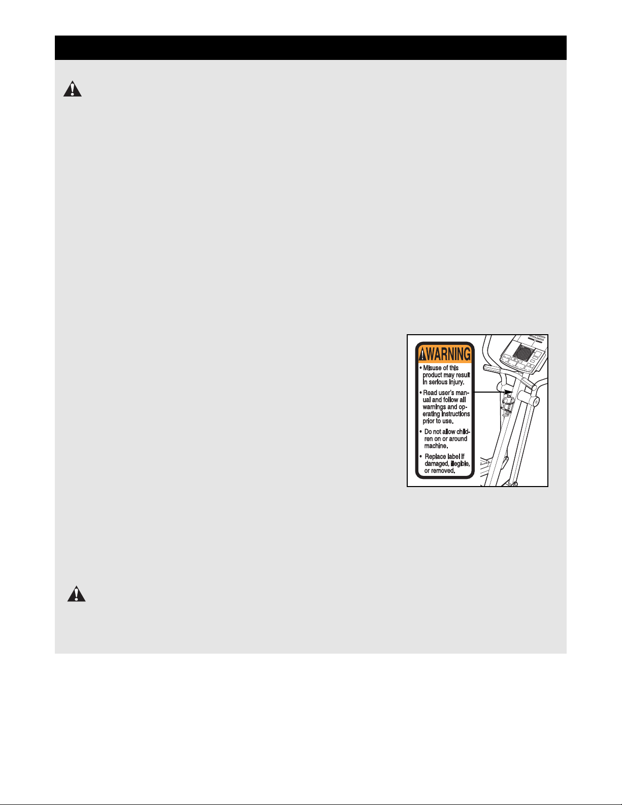
14. The decal
shown at
the right
has been
placed on
the elliptical exerciser in the
indicated
location. If
the decal
is missing
or illegible, please
call our Customer Service Department tollfree at 1-800-999-3756, Monday through
Friday, 6 a.m. until 6 p.m. Mountain Time, to
order a free replacement decal. Apply the
replacement decal in the location shown.
WARNING:Before beginning this or any exercise program, consult your physician.
This is especially important for persons over the age of 35 or persons with pre-existing health problems. Read all instructions before using. ICON assumes no responsibility for personal injury or
property damage sustained by or through the use of this product.
4
BEFORE YOU BEGIN
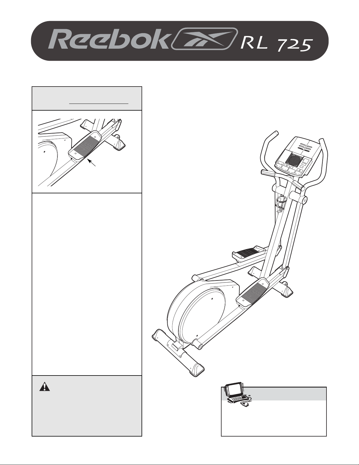
Congratulations for selecting the new REEBOK®RL
725 elliptical exerciser. The RL725 elliptical exerciser
is an incredibly smooth exerciser that moves your feet
in a natural elliptical path, minimizing the impact on
your knees and ankles. And the unique RL725 features adjustable resistance and a state-of-the-art console to help you get the most from your exercise.
Welcome to a whole new world of natural, ellipticalmotion exercise from REEBOK.
For your benefit, read this manual carefully before
you use the elliptical exerciser. If you have ques-
tions after reading this manual, please call our
Customer Service Department toll-free at 1-800-9993756, Monday through Friday, 6 a.m. until 6 p.m.
Mountain Time (excluding holidays). To help us assist
you, please mention the product model number and
serial number when calling. The model number is
RBEL99020. The serial number can be found on a
decal attached to the elliptical exerciser (see the front
cover of this manual for the location of the decal).
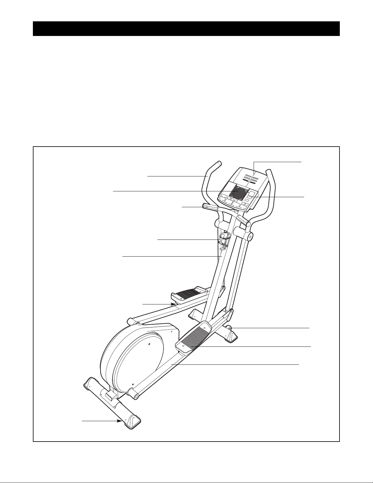
Before reading further, please familiarize yourself with
the parts that are labeled in the drawing below.
Water Bottle Holder*
*No water bottle is included
Upper Body Arm
Handlebar with Pulse Sensor
FRONT
BACK
RIGHT SIDE
Wheel
Pedal
Bookrack
Fan
Console
Upright
Pedal Cushion
Leveling Foot
Pedal Leg
5
Place all parts of the elliptical exerciser in a cleared area and remove the packing materials. Do not dispose of
the packing materials until assembly is completed.
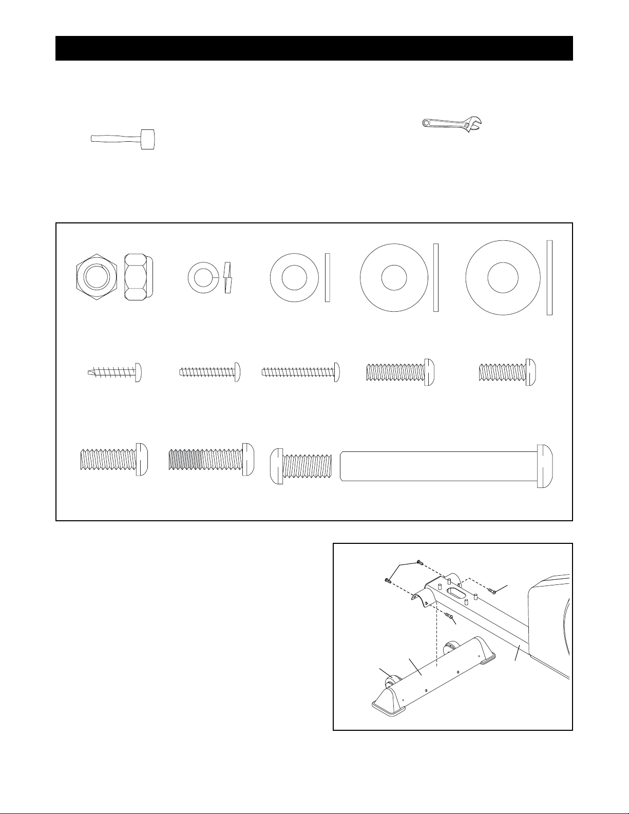
In addition to the included tools, assembly requires an adjustable wrench and a rubber
mallet .
Use the part drawings below to identify the small parts used in assembly. The number in parenthesis below
each drawing refers to the key number of the part, from the PART LIST on page 29. The second number refers
to the quantity used in assembly. Note: Some small parts may have been pre-assembled for shipping. If a
part is not in the parts bag, check to see if it has been pre-assembled.
ASSEMBLY
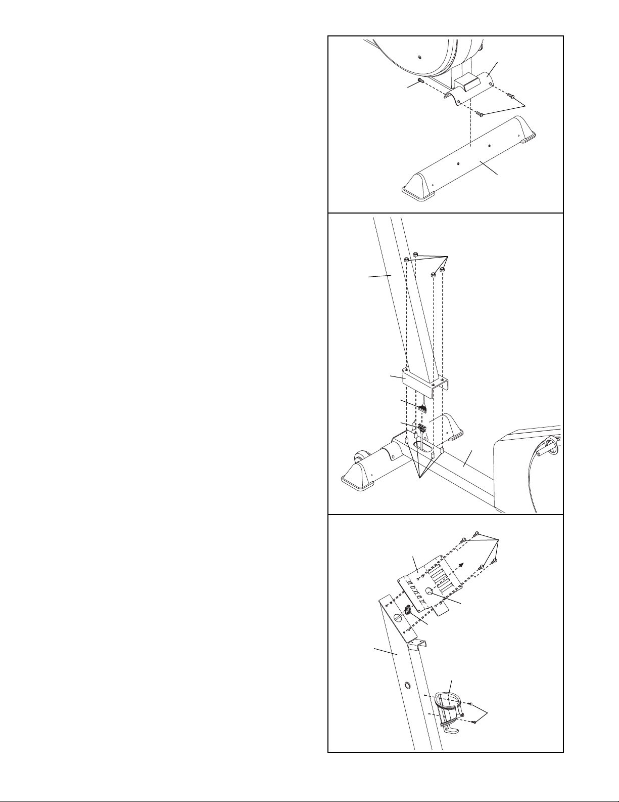
1. Identify the Front Stabilizer (63), which has Wheels
(27) attached to one side. Attach the Front Stabilizer
to the front of the Frame (1) with four M8 x 25mm
Patch Screws (73).
1
27
63
73
73
73
1
M10 Nylon
Locknut (85)–4
M4 x 16mm
Self-tapping
Screw (82)—6
M8 x 19mm Button
Screw (81)–4
M6 Split Washer
(72)–2
M4 x 19mm
Screw (92)–2
M8 x 25mm Patch
Screw (73)–12
Small M8
Washer (71)–2
M4 x 25mm
Screw (96)–2
Washer (70)–2
Screw (75)–4
Large M8
M6 x 20mm
Bolt Set (67)–2
Pedal Arm
Spacer (65)–4
M6 x 16mm Button
Screw (93)–2
6
2. Attach the Rear Stabilizer (24) to the rear of the
Frame (1) with four M8 x 25mm Patch Screws (73).
3. Remove the four M10 Nylon Locknuts (85) from the
welded bolts near the front of the Frame (1).
While a second person holds the Upright (2), connect the Upper Wire Harness (15) to the Lower Wire
Harness (39).
Align the holes in the bracket on the lower end of the
Upright (2) with the welded bolts on the Frame (1).
Lower the Upright, feeding the Upper Wire
Harness (15) and the Lower Wire Harness (39) up
into the Upright, until the welded bolts are fully
inserted into the bracket. Be careful to avoid
pinching and damaging the Wire Harnesses.
Tighten the four M10 Nylon Locknuts (85) onto the
welded bolts on the Frame (1).
4. Feed the Upper Wire Harness (15) up through the
indicated hole in the Console Bracket (3). Attach the
Console Bracket to the Upright (2) with four M8 x
19mm Button Screws (81). Be careful to avoid
pinching and damaging the Upper Wire Harness.
Attach the Water Bottle Holder (13) to the Upright (2)
with two M4 x 19mm Screws (92). Note: The water
bottle holder is designed to be used with your own
water bottle.
2
15
Bracket
Be careful to
avoid pinching
and damaging the
Wire Harnesses
(15, 39) during
this step.
39
Welded
Bolts
1
15
2
Hole
3
81
92
13
85
1
24
73
73
2
3
4
7
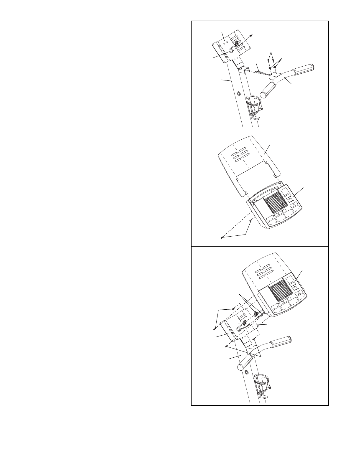
5. While another person holds the Handlebar (4) near
the Upright (2), feed the Pulse Sensor Wire (14) into
the Upright and out of the indicated hole in the
Console Bracket (3). Attach the Handlebar to the
Upright with two M6 x 16mm Button Screws (93)
and two M6 Split Washers (72). Be careful to
avoid pinching and damaging the Pulse Sensor
Wire.
6. Insert the Bookrack (7) into the slots in the Console
(8). Attach the Bookrack to the Console with two M4
x 25mm Screws (96). Be careful to avoid pinching
and damaging the wires in the Console.
7
96
8
5
6
7. While another person holds the Console (8) near
the Console Bracket (3), connect the Pulse Sensor
Wire (14) and the Upper Wire Harness (15) to the
corresponding wires on the Console.
Insert all excess wiring down into the Upright
(2). Attach the Console (8) to the Console Bracket
(3) with four M4 x 16mm Self-tapping Screws (82).
Be careful to avoid pinching and damaging the
Pulse Sensor Wire (14) and the Upper Wire
Harness (15).
3
2
Console
Wires
8
82
82
7
Hole
4
2
3
14
93
72
14
15
8
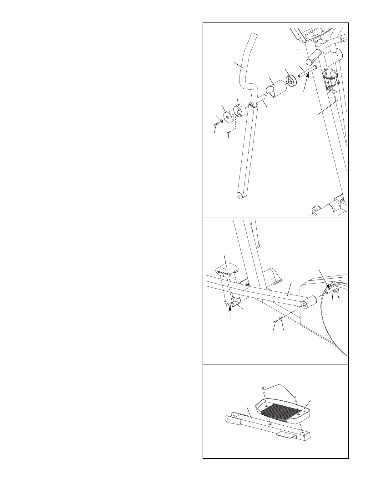
9. Apply a small amount of grease to the axle on the
left Crank Arm (40).
Identify the Left Pedal Leg (28), which is marked
with a decal. Slide the Left Pedal Leg onto the axle
on the left Crank Arm (40). Slide a Large M8
Washer (70) onto an M8 x 25mm Patch Screw (73),
and tighten the Patch Screw into the axle.
Snap a Pedal Cushion (74) around the Left Pedal
Leg (28) onto a Cushion Bracket (99). Make sure that
the arrow on the Pedal Cushion is pointing to one of
the numbers on the Left Pedal Leg and that the number shows through the window in the Cushion
Bracket.
Assemble the Right Pedal Leg (not shown) in the
same way.
10. Identify the Left Pedal Arm (33), which is marked
with a decal. Attach the Left Pedal (35) to the Left
Pedal Arm with two M6 x 20mm Screws (75) as
shown.
Attach the Right Pedal (not shown) to the Right
Pedal Arm (not shown) in the same way.
28
40
Grease
70
73
74
99
Window
9
8. Insert the Pivot Axle (21) into the Upright (2), and
center the Pivot Axle. Apply a small amount of the
included grease to both ends of the Pivot Axle.
Identify the Left Upper Body Arm (5), which is
marked with a decal. Insert an Upright Bushing (20)
into an Upright Spacer (19). Turn the Upright
Spacer so that the semicircular cutout is at the top,
and slide the Upright Spacer onto the post on the
Left Upper Body Arm.
Slide the Left Upper Body Arm (5) onto the Pivot
Axle (21). Attach a Pivot Spacer (17) to the Left
Upper Body Arm with an M4 x 16mm Self-tapping
Screw (82). Turn a Pivot Endcap (16) so that the
rectangular cutout is at the bottom. Using a rubber
mallet, tap the Pivot Endcap into the Pivot Spacer.
Slide a Small M8 Washer (71) onto an M8 x 25mm
Patch Screw (73), and tighten the Patch Screw into
the Pivot Axle (21).
Attach the Right Upper Body Arm (6) in the
same way.
19
17
16
82
73
71
6
Grease
Post
5
21
20
2
8
10
75
35
33
9
12.Make sure that all parts are properly tightened before you use the elliptical exerciser. Note: Some
hardware may be left over after assembly is completed. Place a mat under the exercise cycle to protect
the floor or carpet.
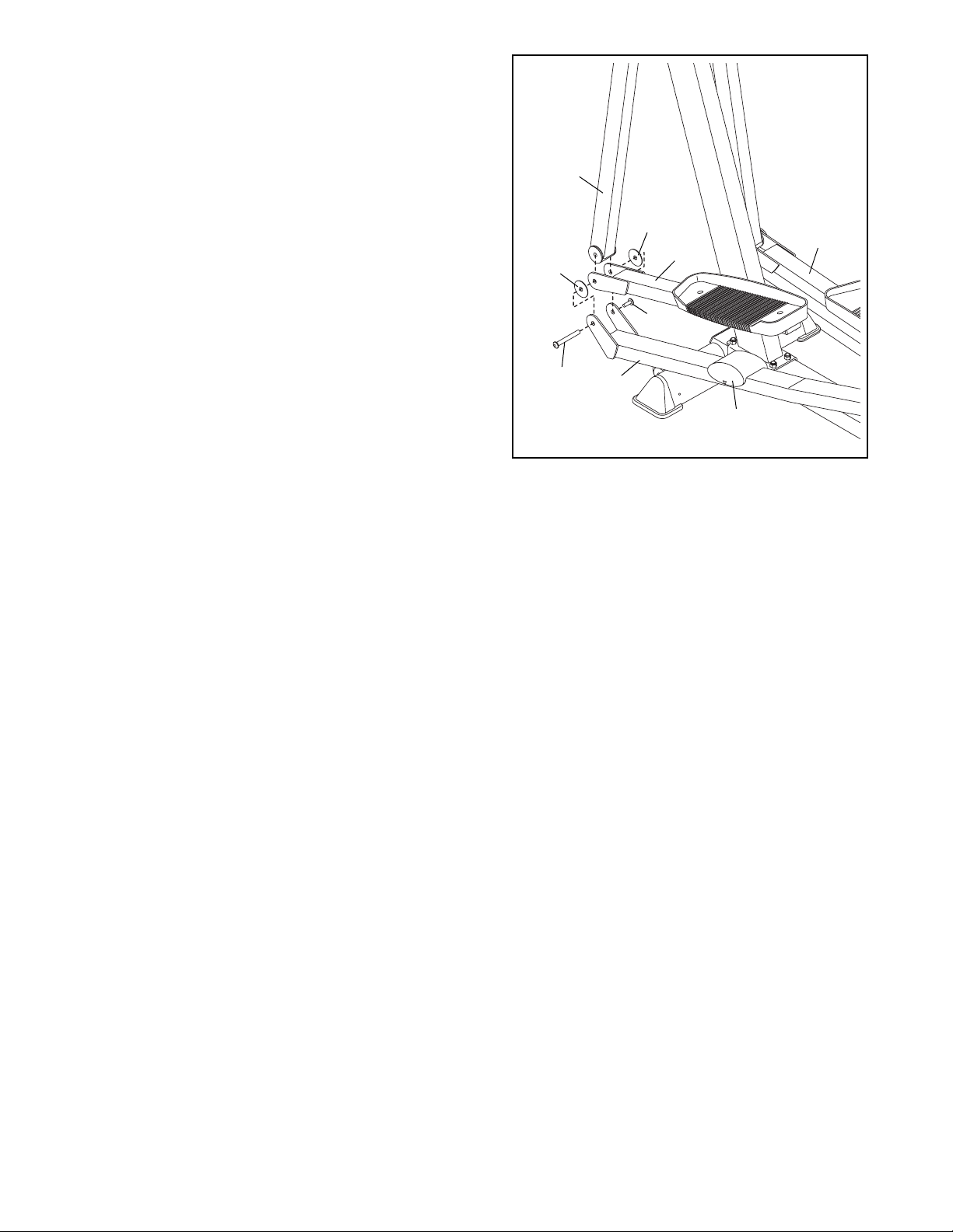
11. Set the Left Pedal Arm (33) on the left Pedal Cushion
(74), and hold the end of the Left Pedal Arm inside of
the bracket on the Left Pedal Leg (28).
Hold a Pedal Arm Spacer (65) between the Left Pedal
Leg (28) and the Left Pedal Arm (33). Insert the long
part of a Bolt Set (67) through the Left Pedal Leg, the
Pedal Arm Spacer, and the Left Pedal Arm.
Lift the Left Pedal Leg (28), and hold the lower end
of the Left Upper Body Arm (5) inside of the bracket
on the Left Pedal Arm (33). Insert the long part of the
Bolt Set (67) through the Left Upper Body Arm. Hold
another Pedal Arm Spacer (65) between the Left
Pedal Arm and the Left Pedal Leg, and insert the
long part of the Bolt Set through these parts. Tighten
the short part of the Bolt Set into the long part.
Attach the Right Pedal Arm (32) in the same way.
65
65
33
32
28
74
67
67
5
11
10
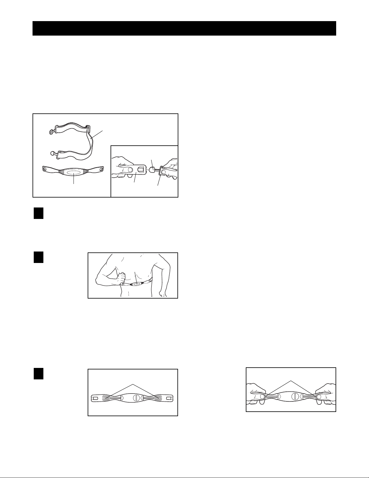
To get the best performance from the chest pulse sensor, please read the instructions below.
HOW TO PUT ON THE CHEST PULSE SENSOR
The chest pulse sensor consists of two components:
the chest strap and the sensor unit. Follow the steps
below to put on the chest pulse sensor.
Refer to the inset drawing above. Insert the tab
on one end of the chest strap through one end of
the sensor unit as shown. Then, press the end of
the sensor unit under the buckle on the chest
strap.
Wrap the
chest pulse
sensor
around
your chest.
Attach the
free end of
the chest
strap to the sensor unit as described above.
Adjust the length of the chest strap, if necessary.
The chest pulse sensor should be under your
clothing, against your skin, and as high under the
pectoral muscles or breasts as is comfortable.
Make sure that the logo is facing forward and is
right-side-up.
Pull the
sensor unit
away from
your body
a few inches and
locate the
two electrode areas on the inner side. Using a
saline solution such as saliva or contact lens
solution, wet both electrode areas. Return the
sensor unit to a position against your chest.
CHEST PULSE SENSOR TROUBLESHOOTING
If the chest pulse sensor does not function properly, or if the displayed heart rate is excessively high
or low, try the steps below.
• Make sure that the chest pulse sensor is worn
exactly as described in step 2 at the left. If the chest
pulse sensor does not function when positioned as
described, move it slightly lower or higher on your
chest.
• Each time you use the chest pulse sensor, use
saline solution such as saliva or contact lens solution to wet the two electrode areas on the sensor
unit (see the drawing in step 3 below). If heart rate
readings do not appear until you begin perspiring,
re-wet the electrode areas.
• Make sure that you are within arm’s length of the
console. For the console to display heart rate
readings, the user must be within arm’s length of
the console.
• The chest pulse sensor is designed to work with
people who have normal heart rhythms. Heart rate
reading problems may be caused by medical conditions such as premature ventricular contractions
(pvcs), tachycardia bursts, and arrhythmia.
• The operation of the chest pulse sensor can be
affected by magnetic interference caused by high
power lines or other sources. If it is suspected that
magnetic interference may be causing a problem,
try relocating the elliptical exerciser.
• If the chest pulse sensor still does not function properly, test the chest pulse sensor in the following way:
Hold the chest
pulse sensor
and place your
thumbs over
the electrode
areas as
shown.
3
2
1
Chest Strap
Sensor Unit
Tab
Buckle
Logo
Electrode Areas
Sensor
Unit
Electrode Areas
HOW TO USE THE CHEST PULSE SENSOR
 Loading...