

Reebok RBEL79740 User Manual
Patent Pending
Visit our website at
www.reebokhomefitness.com
new products, prizes,
fitness tips, and much more!
Model No. RBEL79740
Serial No. _
Serial Number Decal
(underneath frame)
QUESTIONS?
If you have questions, or if there
are missing parts, we will guarantee complete satisfaction
through direct assistance from
our factory.
USER’S MANUAL
TO AVOID DELAYS, PLEASE
CALL DIRECT TO OUR TOLLFREE CUSTOMER HOT LINE.
The trained technicians on our
customer hot line will provide
immediate assistance, free of
charge to you.
CUSTOMER HOT LINE:
1-877-994-4999
Mon.–Fri., 6 a.m.–6 p.m. MST
CAUTION
Read all precautions and instructions in this manual before using
this equipment. Keep this manual
for future reference.

TABLE OF CONTENTS
IMPORTANT PRECAUTIONS . . . . . . . . . . . . . . . . . . . . . . . . . . . . . . . . . . . . . . . . . . . . . . . . . . . . . . . . . . . . . . . .3
BEFORE YOU BEGIN . . . . . . . . . . . . . . . . . . . . . . . . . . . . . . . . . . . . . . . . . . . . . . . . . . . . . . . . . . . . . . . . . . . . . .4
ASSEMBLY . . . . . . . . . . . . . . . . . . . . . . . . . . . . . . . . . . . . . . . . . . . . . . . . . . . . . . . . . . . . . . . . . . . . . . . . . . . . . . .5
ELLIPTICAL EXERCISER OPERATION . . . . . . . . . . . . . . . . . . . . . . . . . . . . . . . . . . . . . . . . . . . . . . . . . . . . . . .10
MAINTENANCE AND TROUBLESHOOTING . . . . . . . . . . . . . . . . . . . . . . . . . . . . . . . . . . . . . . . . . . . . . . . . . . .22
EXERCISE GUIDELINES . . . . . . . . . . . . . . . . . . . . . . . . . . . . . . . . . . . . . . . . . . . . . . . . . . . . . . . . . . . . . . . . . . .23
PART LIST . . . . . . . . . . . . . . . . . . . . . . . . . . . . . . . . . . . . . . . . . . . . . . . . . . . . . . . . . . . . . . . . . . . . . . . . . . . . . .24
EXPLODED DRAWING . . . . . . . . . . . . . . . . . . . . . . . . . . . . . . . . . . . . . . . . . . . . . . . . . . . . . . . . . . . . . . . . . . . .26
ORDERING REPLACEMENT PARTS . . . . . . . . . . . . . . . . . . . . . . . . . . . . . . . . . . . . . . . . . . . . . . . . . .Back Cover
LIMITED WARRANTY . . . . . . . . . . . . . . . . . . . . . . . . . . . . . . . . . . . . . . . . . . . . . . . . . . . . . . . . . . . . . .Back Cover
REEBOK and the Vector Logo are registered trademarks and service marks of Reebok. This product is
manufactured and distributed under license from Reebok International.
2

IMPORTANT PRECAUTIONS
WARNING:To reduce the risk of serious injury, read the following important precau-
tions before using the elliptical exerciser.
1. Read all instructions in this manual before
using the elliptical exerciser.
2. It is the responsibility of the owner to ensure
that all users of the elliptical exerciser are
adequately informed of all precautions.
3. The elliptical exerciser is intended for
in-home use only. Do not use the elliptical
exerciser in a commercial, rental, or institutional setting.
4. Place the elliptical exerciser on a level surface, with a mat beneath it to protect the
floor or carpet. Keep the elliptical exerciser
indoors, away from moisture and dust.
5. Inspect and properly tighten all parts regularly. Replace any worn parts immediately.
6. Keep children under age 12 and pets away
from the elliptical exerciser at all times.
7. The elliptical exerciser should not be used
by persons weighing more than 250 pounds.
8. Wear appropriate exercise clothes when
using the elliptical exerciser. Always wear
athletic shoes for foot protection.
9. Keep your back straight when using the elliptical exerciser; do not arch your back.
10. Always hold the handlebars or the upper
body arms when mounting, dismounting, or
using the elliptical exerciser.
11. If you feel pain or dizziness at any time
while exercising, stop immediately and cool
down.
12. The pulse sensor is not a medical device.
Various factors, including the user's movement, may affect the accuracy of heart rate
readings. The pulse sensor is intended only
as an exerci se aid in determining heart rate
trends in general.
13. When you stop exercising, allow the pedals
to slowly come to a stop. The elliptical exerciser does not have a free wheel; the pedals
will continue to move until the flywheel
stops.
14. Always unplug the power cord immediately
after use and before cleaning the elliptical
exerciser.
15. The decals shown on page 4 have been
placed on the elliptical exerciser. If a decal
is missing or illegible, please call our
Customer Service Department toll-fr ee at
1-877-994-4999 and order a free replacement
decal. Apply the decal in the location shown.
WARNING:Before beginning this or any exercise program, consult your physician.
This is especially important for persons over the age of 35 or persons with pre-existing health problems. Read all instructions before using. ICON assumes no responsibility for personal injury or
property damage sustained by or through the use of this product.
3
BEFORE YOU BEGIN
Congratulations for selecting the new REEBOK®RL
645 elliptical exerciser
smooth exerciser that moves your feet in a natural
elliptical path, minimizing the impact on your knees
and ankles. And the unique RL 645 features
adjusta b le re s is t an c e and incline to help you get the
most from your exercise. Wel co m e t o a whol e n ew
world of natural, elliptical-motion exercise fr om
REEBOK.
For your benefit, read this manual carefully before
you use the elliptical exerciser. If you have ques-
. The RL 645 is an incredibly
Book Rack
Upper Body Arm
Console
tions after reading this manual, please call our
Customer Service
4999, Monday through Friday
Mountain Time (excluding holidays). To help us assist
you, please note the product model number and serial
number before calling. The model number is
RBEL79740. The serial number can be found on a
decal attached to the elliptical exerciser (see the front
cover of this manual for the location of the decal).
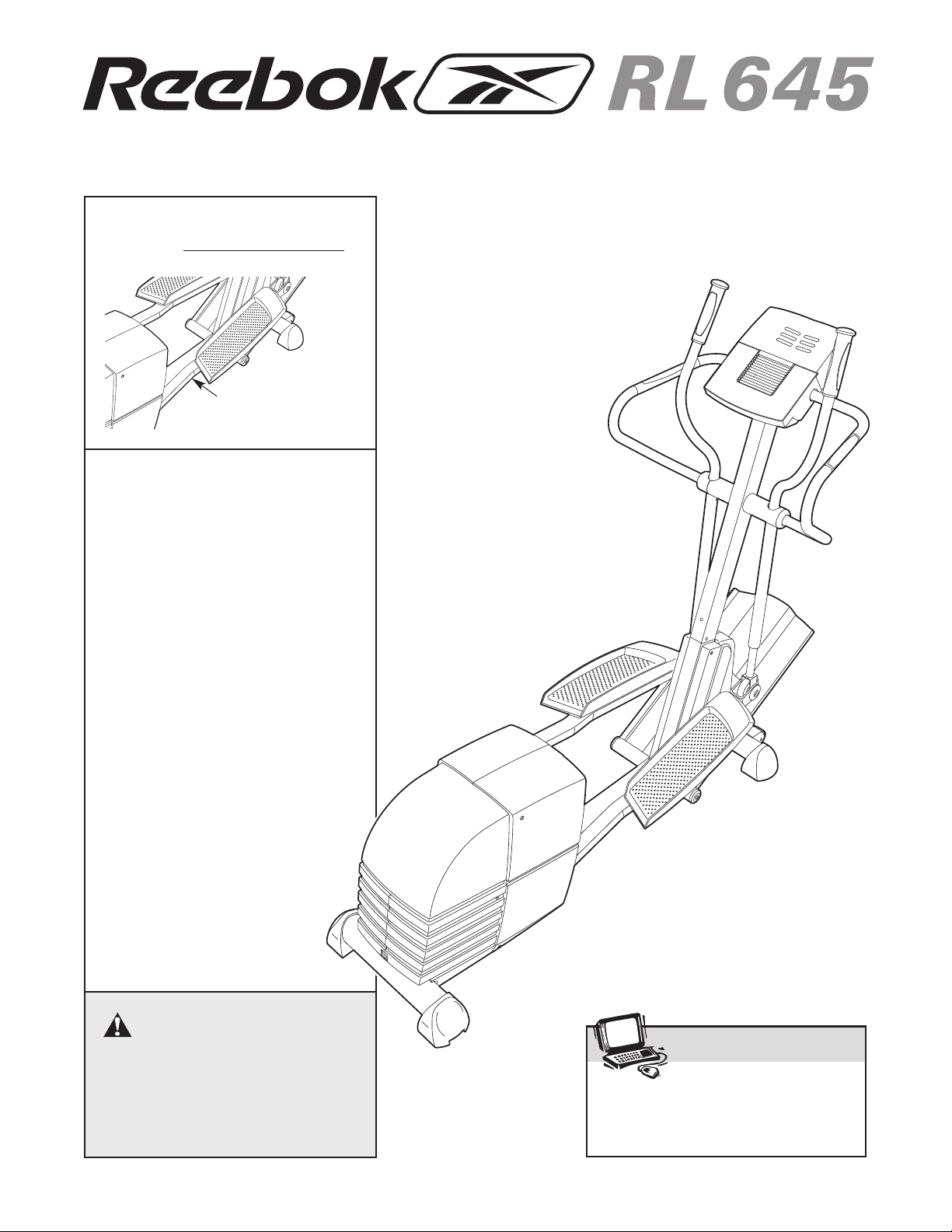
Before reading further, please familiarize yourself with
the parts that are labeled in the drawing below.
Department toll-free at 1-877-994-
, 6 a.m. until 6 p.m.
Fan
Pulse Sensor
LEFT SIDE
BACK
Upright
Power Receptacle
Handlebar
Ramp
Wheel
Pedal
Pedal Leg
RIGHT SIDE
Leveling Foot
4

M10 x 92mm Carriage Bolt (124)–2
M6 Washer
(102)–2
M10 x 25mm Button
Screw (123)–3
M8 Washer
(132)–4
M8 x 35mm Button
Bolt (117)–2
M8 x 42mm Button
Bolt (116)–4
M4 x 16mm
Screw (99)–4
M8 Jam Nut
(91)–6
M10 Split
Washer (118)–3
M10 x 105mm Button Screw (89)–2
M4 x 16mm Round
Head Screw (125)–1
M6 x 16mm Button
Screw (103)–4
Bolt Set (101)–2
M10 Nylon
Locknut (90)–2
M8 x 52mm Button
Bolt (100)–4
M8 Split
Washer (122)–4
M4 x 25mm Round
Head Screw (115)–2
ASSEMBLY
Assembly requires two persons. Place all parts of the elliptical exerciser in a cleared area and remove the
packing materials. Do not dispose of the packing materials until assembly is completed. In addition to the
included allen wrenches, assembly requires a phillips screwdriver , two adjustable
wrenches , a rubber mallet
As you assemble the elliptical exerciser, use the drawings below to identify the small parts used for assembly.
The number in parenthesis below each drawing is the key number of the part, from the PART LIST on pages 24
and 25. The number following the key number is the quantity used for assembly. Note: Some small parts may
have been pre-assembled. If a part is not in the parts bag, check to see if it has been pre-assembled.
, and pliers .
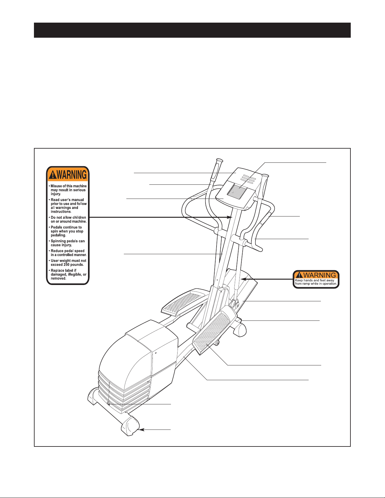
1. Identify the Front Stabilizer (29), which has Wheels (44)
attached to the front. While another person lifts the
front of the Frame (1), attach the Front Stabilizer to the
Frame with two M10 x 92mm Carriage Bolts (124) and
two M10 Nylon Locknuts (90).
1
124
5
44
29
90
1
2. While another person lifts the rear of the Frame (1),
attach the Rear Stabilizer (30) to the Frame with two
M10 x 105mm Button Screws (89).
2
30
1
89
3. Identify the Ramp Axle (39), which is the longest axle.
Next, identify the Ramp Axle Covers (41), which are
smaller than the Wheel Covers (not shown). Slide a
Ramp Axle Cover onto an M6 x 16mm Button Screw
(103) as shown. Tighten the Button Screw into one
end of the Ramp Axle. Apply a small amount of the
included grease to the Ramp Axle.
Have a second person hold the two Ramp Bushings
(40) against the indicated tubes on the Frame (1).
Align the tubes on the Ramp (33) with the Ramp
Bushings;
shown. Insert the open end of the Ramp Axle (39) into
the Ramp, the Ramp Bushings, and the Frame. If necessary, tap the Ramp Axle with a rubber mallet to
insert it.
Slide the other Ramp Axle Cover (41) onto an M6 x
16mm Button Screw (103) as shown. Tighten the
Button Screw into the open end of the Ramp Axle (39).
4. Slide an M6 Washer (102) onto an M6 x 16mm Button
Screw (103). Tighten the Button Screw into one end of
the Lift Axle (38). Apply a small amount of grease to
the Lift Axle.
make sure that the Ramp is turned as
3
103
4
33
Grease
39
41
33
40
Tubes
103
41
40
Tubes
1
Raise the Ramp (33). Insert the Lift Axle (38) into the
welded tube under one side of the Ramp, through the
motor screw, and then into the welded tube under the
other side of the Ramp. As you insert the Incline
Axle through the motor screw
motor screw does not turn.
Slide an M6 Washer (102) onto an M6 x 16mm Button
ighten the Button Screw into the open
Screw (103).
end of the Lift Axle (38).
T
, make sure that the
Motor
Screw
103
102
38
Grease
103
102
6
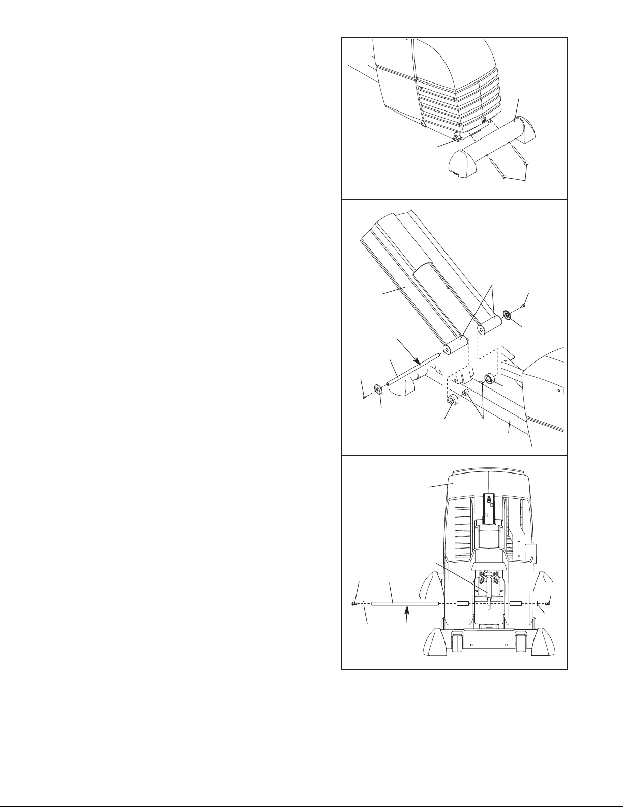
5. Hold a Ramp Wheel (50) inside of the bracket on one
of the Chrome Tubes (45). Hold the Chrome Tube and
the Ramp Wheel inside of the bracket on the Left
Pedal Leg (46). Slide a Wheel Cover (51) onto the
long part of a Bolt Set (101), and insert the Bolt Set
into the Left Pedal Leg, the Chrome Tube, and the
Ramp Wheel.
5
45
101
Slide a Wheel Cover (51) onto the short part of the
Bolt Set (101). Then, tighten the short part of the Bolt
Set into the long part.
Attach the other Chrome Tube (not shown) and the
other Ramp Wheel (not shown) to the right side of
the elliptical exerciser in the same way.
6. Identify the Left Pedal (48), which is marked with an
“L.” Attach the Left Pedal to the Left Pedal Leg (46)
with two M8 x 52mm Button Bolts (100), two M8 Split
Washers (122), and two M8 Washers (132).
Attach the Right Pedal (not shown) to the Right
Pedal Leg (not shown) in the same way.
46
50
101
51
6
132
122
51
48
46
132
122
7. Have another person hold the Upright (2) in the position shown. Make sure that the Upright is turned so
that the three holes are aligned with the holes in
the Frame (1).
Connect the Upper Wire Harness (18) to the Lower
Wire Harness (53). Carefully pull the upper end of
the Upper Wire Harness to remove the slack from
the Wire Harnesses. Slide the Upright (2) onto the
Frame (1). Be careful to avoid pinching the W
Harnesses. Attach the Upright to the Frame with three
M10 x 25mm Button Screws (123) and three M10 Split
Washers (118).
ire
100
7
2
1
118
123
18
123
118
18
53
1
7
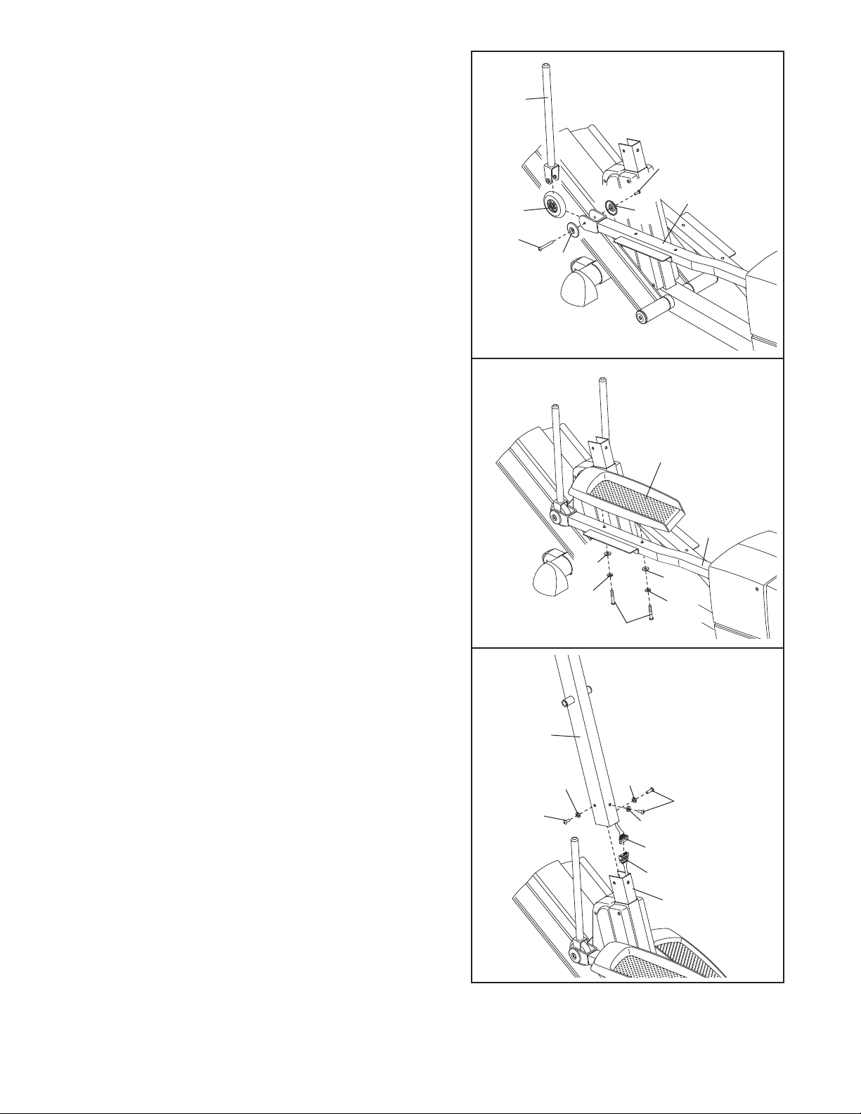
8. Apply a small amount of the included Teflon®lubricant
to a paper towel. Rub a thin film of the lubricant onto
each Chrome
Tube (45).
8
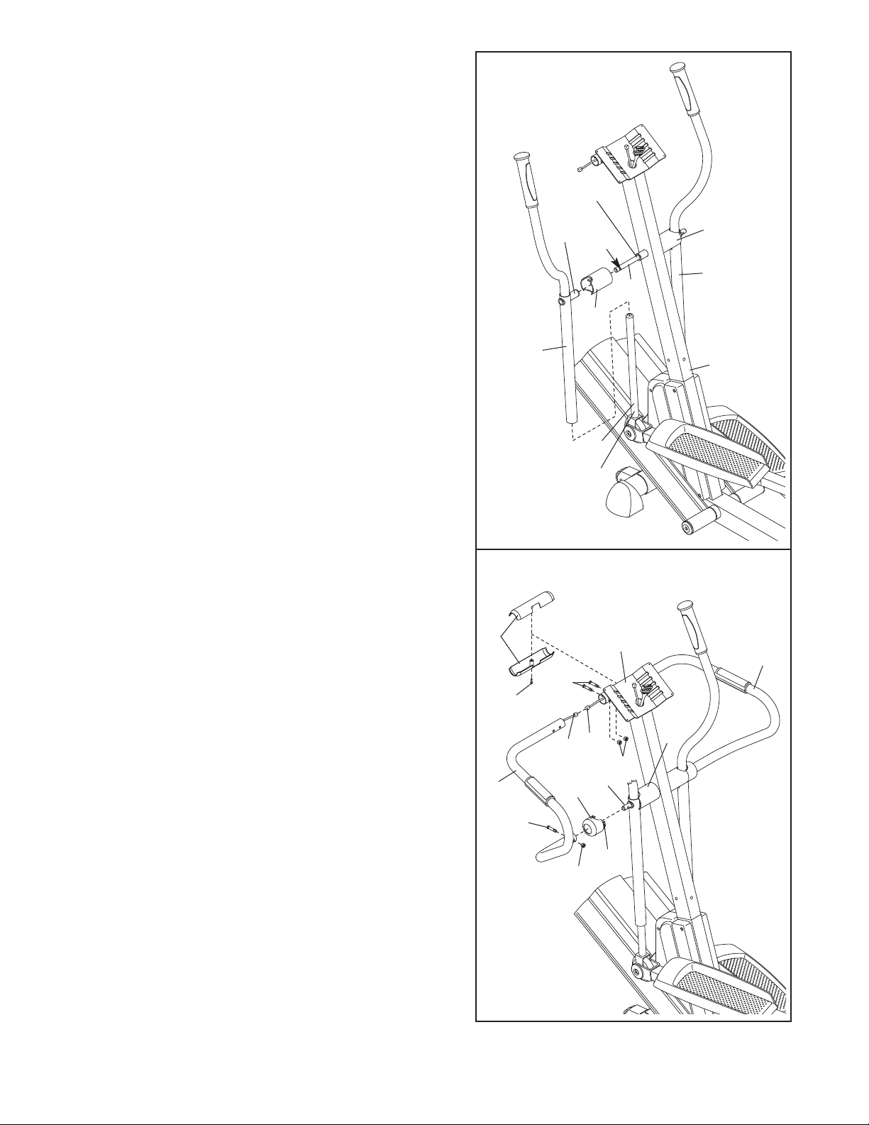
Identify the Left Upper Body
with an “L.” Slide the Left Upper Body Arm onto the left
Chrome Tube (45). Slide the Right Upper Body Arm
(10) onto the right Chrome Tube (not shown). Make
sure that the Upper Body Arms are on the correct
sides. Next, slide an Upper Body Cover (15) onto the
post on each Upper Body Arm.
Apply grease to the Pivot Axle (16). Insert the Pivot
Axle into the Upright (2), the right Upper Body Cover
(15), and the Right Upper Body Arm (10). Next, push
the Pivot Axle into the Upright
Pivot Axle is flush with the left side of the Upright.
Then, raise the Left Upper Body Arm (9), and insert
the Pivot Axle into the left Upper Body Cover and the
Left Upper Body Arm. Center the Pivot Axle and rotate
it so the indicated hole is in the position shown.
Arm (9), which is marked
until the left end of the
Post
9
Lubricate
Grease
15
Hole
10
16
15
2
45
9. Have another person hold the Left Handlebar (7) near
the Upright (2) as shown. Connect the left Pulse
Sensor Wire (11) to the Pulse Extension Wire (17).
Slide a Handlebar Cap (12) onto the lower end of the
Left Handlebar.
Slide the upper end of the Left Handlebar (7) into the
tube on the front of the Upright (2), while sliding the
lower end of the Left Handlebar onto the Pivot Axle
(16). Attach the upper end of the Left Handlebar with
two M8 x 42mm Button Bolts (116) and two M8 Jam
1,
Nuts (91); be careful not to damage the W
17) as you insert the Button Bolts. Make sure that
the Jam Nuts are resting in the hexagonal holes in
the tube on the front of the Upright.
end of the Left Handlebar with an M8 x 35mm Button
Bolt (117) and an M8 Jam Nut (91). Press the tabs on
the Handlebar Cap (12) into the left Upper Body Cover
(15).
Attach the Right Handlebar (8) to the Upright (2) in the
same way.
Hold the halves of the Upper Handlebar Cover (5)
around the tube on the front of the Upright (2).
the Upper Handlebar Cover with an M4 x 16mm Round
Head Screw (125);
Wires (11, 17).
be careful not to damage the
ires (1
Attach the lower
Attach
9
5
125
7
2
116
17
11
91
16
12
17
1
T
ab
91
15
8
8
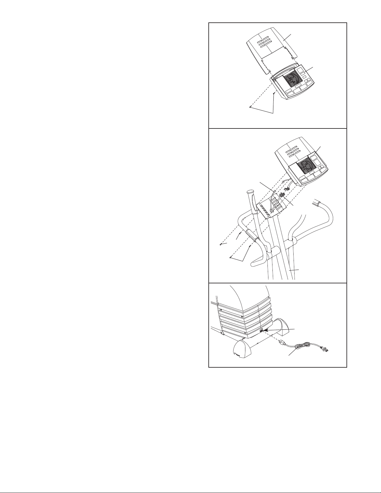
10.Attach the Book Rack (4) to the Console (3) with two
M4 x 25mm Round Head Screws (1
15).
10
4
3
115
11.Have another person hold the Console (3) near the
Upright (2).
Connect the Upper Wire Harness (18) to the wire harness on the Console (3). Connect the Pulse Extension
Wire (17) to the pulse wire on the Console.
Carefully insert all excess wiring down into the Upright
(2). Attach the Console (3) to the Upright with four M4
x 16mm Screws (99).
the wires.
12.Plug the Power Cord (83) into the Power Receptacle
(82) at the rear of the elliptical exerciser
Be careful to avoid pinching
.
11
Do not pinch
the wires
during this step.
99
99
12
3
17
18
2
82
83
13.Make sure that all parts of the elliptical exerciser are properly tightened. Cover the floor beneath the
elliptical exerciser to protect the floor from damage. Note: Some extra hardware may be left over.
9
 Loading...