

Page 1
CAUTION
Read all precautions and instructions in this manual before using
this equipment. Keep this manual
for future reference.
Model No. RBEL68080
Serial No. __
Serial
Number
Decal
QUESTIONS?
If you have questions, or if there
are missing or damaged parts,
please call direct to our toll-free
Customer Hot Line. The trained
technicians on our Customer Hot
Line will provide immediate
assistance, free of charge to you.
CUSTOMER HOT LINE:
1-800-999-3756
Mon.ÐFri., 6 a.m.Ð6 p.m. MST
USERÕS MANUAL
U.S. Patent No. 5,573,480
Other patents pending
Page 2
2
TABLE OF CONTENTS
LIMITED WARRANTY . . . . . . . . . . . . . . . . . . . . . . . . . . . . . . . . . . . . . . . . . . . . . . . . . . . . . . . . . . . . . . . . . . .2
IMPORTANT PRECAUTIONS . . . . . . . . . . . . . . . . . . . . . . . . . . . . . . . . . . . . . . . . . . . . . . . . . . . . . . . . . . . . .3
BEFORE YOU BEGIN . . . . . . . . . . . . . . . . . . . . . . . . . . . . . . . . . . . . . . . . . . . . . . . . . . . . . . . . . . . . . . . . . . .4
PART IDENTIFICATION CHART . . . . . . . . . . . . . . . . . . . . . . . . . . . . . . . . . . . . . . . . . . . . . . . . . . . . . . . . . . .5
ASSEMBLY . . . . . . . . . . . . . . . . . . . . . . . . . . . . . . . . . . . . . . . . . . . . . . . . . . . . . . . . . . . . . . . . . . . . . . . . . . .6
HOW TO USE THE ELLIPTICAL CROSSTRAINER . . . . . . . . . . . . . . . . . . . . . . . . . . . . . . . . . . . . . . . . . . . . .8
MAINTENANCE AND TROUBLE-SHOOTING . . . . . . . . . . . . . . . . . . . . . . . . . . . . . . . . . . . . . . . . . . . . . . . .10
CONDITIONING GUIDELINES . . . . . . . . . . . . . . . . . . . . . . . . . . . . . . . . . . . . . . . . . . . . . . . . . . . . . . . . . . . .12
PART LIST . . . . . . . . . . . . . . . . . . . . . . . . . . . . . . . . . . . . . . . . . . . . . . . . . . . . . . . . . . . . . . . . . . . . . . . . . . .14
EXPLODED DRAWING . . . . . . . . . . . . . . . . . . . . . . . . . . . . . . . . . . . . . . . . . . . . . . . . . . . . . . . . . . . . . . . . .15
HOW TO ORDER REPLACEMENT PARTS . . . . . . . . . . . . . . . . . . . . . . . . . . . . . . . . . . . . . . . . . . .Back Cover
LIMITED WARRANTY
ICON Health & Fitness, Inc. (ICON), warrants this product to be free from defects in workmanship and
material, under normal use and service conditions, for a period of ninety (90) days from the date of purchase. This warranty extends only to the original purchaser. ICONÕs obligation under this warranty is limited to replacing or repairing, at ICONÕs option, the product at one of its authorized service centers. All
products for which warranty claim is made must be received by ICON at one of its authorized service centers with all freight and other transportation charges prepaid, accompanied by sufficient proof of purchase.
All returns must be pre-authorized by ICON. This warranty does not extend to any product or damage to
a product caused by or attributable to freight damage, abuse, misuse, improper or abnormal usage or
repairs not provided by an ICON authorized service center, to products used for commercial or rental purposes, or to products used as store display models. No other warranty beyond that specifically set forth
above is authorized by ICON.
ICON is not responsible or liable for indirect, special or consequential damages arising out of or in connection with the use or performance of the product or damages with respect to any economic loss, loss
of property, loss of revenues or profits, loss of enjoyment or use, costs of removal, installation or other
consequential damages of whatsoever nature. Some states do not allow the exclusion or limitation of incidental or consequential damages. Accordingly, the above limitation may not apply to you.
The warranty extended hereunder is in lieu of any and all other warranties and any implied warranties of
merchantability or fitness for a particular purpose is limited in its scope and duration to the terms set forth
herein. Some states do not allow limitations on how long an implied warranty lasts. Accordingly, the above
limitation may not apply to you.
This warranty gives you specific legal rights. You may also have other rights which vary from state to state.
ICON Health & Fitness, Inc. 1500 S. 1000 W., Logan, UT 84321-9813
REEBOK and the Vector Logo are registered trademarks and service marks of Reebok. This product is
manufactured and distributed under license from Reebok International.
Page 3

3
1. Read all instructions in this manual before
using the elliptical crosstrainer.
2. It is the responsibility of the owner to
ensure that all users of the elliptical
crosstrainer are adequately informed of all
precautions.
3. Place the elliptical crosstrainer on a level
surface, with a mat beneath it to protect the
floor or carpet. Keep the elliptical crosstrainer indoors, away from moisture and dust.
4. Inspect and tighten all parts regularly.
Replace any worn parts immediately.
5. Keep children under the age of 12 and pets
away from the elliptical crosstrainer at all
times.
6. The elliptical crosstrainer should not be
used by persons weighing more than 250
pounds.
7. Wear appropriate exercise clothing when
using the elliptical crosstrainer. Always wear
athletic shoes for foot protection.
8. Always hold the handlebars when mounting,
dismounting, or using the elliptical
crosstrainer. Make sure to step onto and off
the pedal that is in the lowest position when
mounting and dismounting.
9. Each time you stop exercising, allow the
pedals to slowly come to a stop.
10. Keep your back straight when using the
elliptical crosstrainer. Do not arch your
back.
11. If you feel pain or dizziness while exercising, stop immediately and begin cooling
down.
12. The elliptical crosstrainer is intended for
in-home use only; do not use it in any
commercial, rental, or institutional setting.
13. The decal shown below is found on the elliptical crosstrainer. If the decal is missing, or
if it is not legible, call toll-free 1-800-9993756 to order a free replacement decal.
Apply the decal in the location shown.
WARNING: Before beginning this or any exercise program, consult your physician. This is especially important for persons over the age of 35 or persons with pre-existing health problems. Read
all instructions before using. ICON assumes no responsibility for personal injury or property
damage sustained by or through the use of this product.
IMPORTANT PRECAUTIONS
WARNING: To reduce the risk of serious injury, read the following important precautions before
using the REEBOK elliptical crosstrainer.
(Decal is not shown actual size)
Page 4
4
BEFORE YOU BEGIN
Congratulations for selecting the REEBOK
¨
elliptical crosstrainer. The REEBOK¨elliptical
crosstrainer is an incredibly smooth exerciser that
moves your feet in a natural elliptical path, minimizing
the impact on your knees and ankles. And the
REEBOK¨elliptical crosstrainer features both upperbody and lower-body exercise, adjustable resistance,
and motivational electronics to help you get the most
from each workout. Welcome to a whole new world of
natural, elliptical-motion exercise.
For your benefit, read this manual carefully before
you use the REEBOK¨elliptical crosstrainer. If you
have additional questions, please call our Customer
Service Department toll-free at 1-800-999-3756,
Monday through Friday, 6 a.m. until 6 p.m. Mountain
Time (excluding holidays). To help us assist you,
please note the product model number and serial
number before calling. The model number is
RBEL68080. The serial number can be found on a
decal attached to the elliptical crosstrainer (see the
front cover of this manual for the location of the decal).
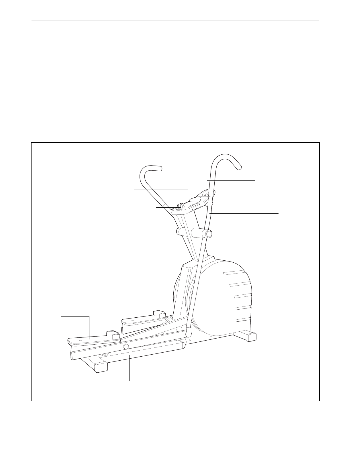
Before reading further, please look at the drawing
below and familiarize yourself with the parts that are
labeled.
Upright
Resistance Knob
Water Bottle Holder
(Bottle not included)
FRONT
BACK
RIGHT SIDE
Pedal
Handlebar
Hood
Pedal Wheel Frame
Console
Book Holder
Page 5
5
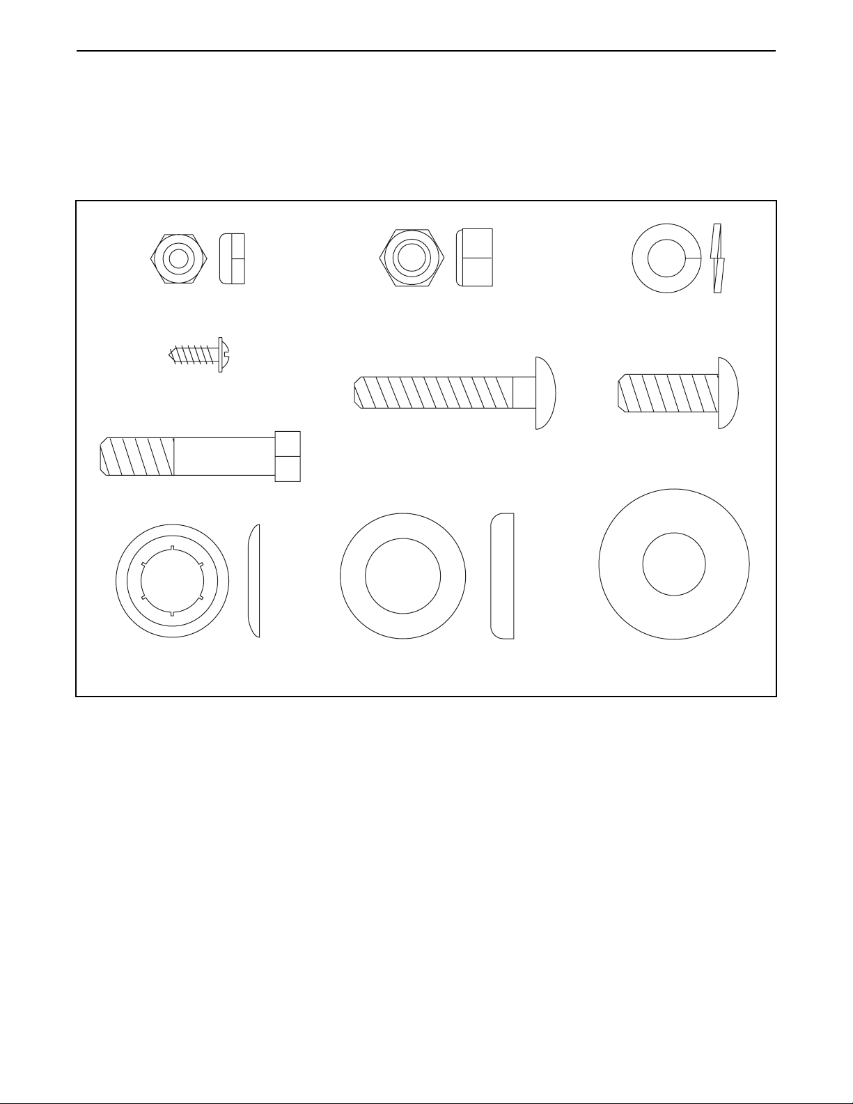
PART IDENTIFICATION CHART
Use the chart below to identify the small parts used in
assembly. The number in parenthesis below each part
is the key number of the part, from the PART LIST on
page 14. The number after the dash indicates the
quantity needed for assembly. Note: Some small
parts may have been pre-attached. If a part is not
in the parts bag, check to see if it has been preattached.
3/8" Button Head
Screw (65)Ñ5
3/8" x 1 3/4" Bolt (84)Ð2
5/16" x 1 3/4" Carriage
Bolt (61)Ð2
3/8" Lock Washer (66)Ñ3
3/8" Nylon Locknut (85)Ð2
5/16" Nylon Jam Nut (62)Ð2
#8 x 1/2" Screw (64)Ð6
(packaged with console)
5/8" Washer (59)Ñ2
3/4" Spacer (58)Ñ2
5/8" Push Nut (60)Ñ2*
*Extra 5/8Ó Push Nuts may be included
Page 6

6
ASSEMBLY
Assembly requires two persons. Place all parts of the elliptical crosstrainer in a cleared area and remove the
packing materials. Do not dispose of the packing materials until assembly is completed.
Assembly requires the included allen wrench and push nut tool , and your own phillips
screwdriver and two adjustable wrenches .
2. Hold the Upright (6) in the position shown. Carefully
pull the Resistance Control Wire (48) and the Reed
Switch Wire (52) up through the Upright until there is
no slack between the Upright and the Frame (1).
Slide the Upright (6) onto the Frame (1). Be careful
to avoid pinching the Resistance Control Wire
(48) and the Reed Switch Wire (52). Tighten a 3/8Ó
Button Head Screw (65) and a 3/8Ó Lock Washer
(66) into the front of the Upright and the Frame.
Next, tighten two 3/8Ó Button Head Screws and 3/8Ó
Lock Washers into the sides of the Upright and the
Frame. Note: It may be necessary to loosen the front
Button Head Screw slightly in order to attach the
other two Button Head Screws. Firmly tighten all
three Button Head Screws.
1. Attach a Wheel Bracket (82) to the front of the
Frame (1) with a 3/8Ó Button Head Screw (65).
Attach a Wheel (83) to the Wheel Bracket with a 3/8Ó
x 1 3/4Ó Bolt (84) and a 3/8Ó Nylon Locknut (85).
Make sure that the Wheel still turns after you have
tightened these parts. Attach the other Wheel
Bracket and Wheel to the Frame in the same way.
Press two 2Ó x 3Ó Caps (38) onto the front of the
Frame (1). Press the other two 2Ó x 3Ó Caps onto the
back of the Frame (not shown).
2
6
48
52
65
65
65
66
66
1
1
1
38
84
85
83 65
82
3. The Console (43) requires two ÒAAÓ batteries (not
included). Alkaline batteries are recommended.
To install batteries, turn over the Console (43) (see
the inset drawing). Insert two batteries into the battery clip. Make sure that the negative ends of the
batteries (marked ÒÐÓ) are touching the springs
in the battery clip.
3
43
43
Batteries
Battery Clip
Page 7

7
7. Make sure that all parts of the elliptical crosstrainer are properly tightened. To protect the floor or carpet
from damage, place a mat under the elliptical crosstrainer.
5. Slide a 3/4Ó Spacer (58) onto the left side of the
Upright (6). Make sure that the open side of the
Spacer is facing the Upright. Next, press a Plastic
Washer (55) into a Large Pivot Cover (54). Make
sure that the Plastic Washer is turned so it is flush
with the Large Pivot Cover. Slide the Plastic Washer
and the Large Pivot Cover onto the Upright.
Make sure that there are two Bushings (22) in the
Left Handlebar (5). Slide the Left Handlebar onto the
Upright (6).
Slide a Small Pivot Cover (56) and a 5/8Ó Washer
(59) onto the Upright (6). Using the included push
nut tool, tap a Push Nut (60) onto the Upright (see
the inset drawing). Press a Pivot Cap (57) into the
Small Pivot Cover.
Repeat this step to attach the Right Handlebar (not
shown).
6. Make sure that there are two 3/4Ó Bushings (18) in
the front end of the Right Outer Leg (2). Attach the
Right Handlebar (4) to the Right Outer Leg with a
5/16Ó x 1 3/4Ó Carriage Bolt (61) and a 5/16Ó Nylon
Jam Nut (62). Make sure that the head of the
Carriage Bolt is in the square hole in the Right
Handlebar.
Attach the Left Handlebar (5) to the Left Outer Leg
(3) in the same way.
6
4
5
3
2
62
61
5
58
55
54
5
56
59
60
57
6
22
48
64
64
43
63
48
6
6
52
43
Hole
4
4. Refer to the inset drawing. Detach the Reed Switch
Wire (52) from the Resistance Control Wire (48).
Plug the Reed Switch Wire into the back of the
Console (43). Next, route the Resistance Control
Wire (48) on top of the Upright (6) so that it will fit
beneath the Console (43). Make sure that the
Resistance Control Wire is not kinked and that it
does not block the indicated hole.
Place the Console (43) on top of the Upright (6).
Attach the Console with six #8 x 1/2Ó Screws (64).
Press the Resistance Knob (63) firmly onto the
Resistance Control (48).
60
6
Push Nut
Tool
18
Page 8

DESCRIPTION OF THE CONSOLE
The innovative console offers a manual mode and
three pacer programs. The pacer programs are
designed to help you achieve your exercise goals by
pacing your exercise. The console also features six
monitor modes that provide continuous exercise
feedback.
HOW THE PACER PROGRAMS OPERATE
When you use a
pacer program,
two columns of
bars will appear
in the display.
The left column
will show a target
pace, which is
determined by
the program you
have selected;
the right column will show your actual pace. The target
pace will change periodically during the program; as
the target pace changes, simply adjust your pace to
keep both columns at the same height. Important:
The target pace is a goal pace. Your actual pace
may be slower than the target pace, especially
during the first few months of your exercise program. Be sure to exercise at a pace that is comfortable for you.
The three graphs on the console show how the target
pace will change during the pacer programs (see the
drawing at the left). Each graph is divided into ten
columns, and each column represents a two-minute
time period. The bars in each column show what the
target pace will be during that two-minute period. For
example, in the first column of graph 1, there is one
bar. This shows that during the first two minutes of
program 1, the target pace will be about 1.5 miles per
hour (see the scale at the left end of the graph). In the
second column, there are five bars. This shows that
during the second two-minute period, the target pace
will be almost 4.5 mph. Each pacer program is twenty
minutes long.
DESCRIPTION OF THE MONITOR MODES
The six monitor modes provide continuous exercise
feedback. The modes are described below.
¥ SpeedÑThis mode shows your pace, in miles per
hour.
¥ TimeÑIf you select one of the three pacer programs,
this mode will count down the time remaining in the
program. If you select the manual mode, this mode
will count up the length of time you have exercised.
Note: If you stop exercising for ten seconds or
longer, the time mode will pause.
¥ DistanceÑThis mode shows the distance you have
completed, in miles.
¥ Fat calories (FAT CALS)ÑThis mode shows the
approximate number of fat calories you have
burned. (See BURNING FAT on page 12 for an
explanation of fat calories.)
¥ Calories (CALS)ÑThis mode shows the approxi-
mate number of calories you have burned. (This
number includes both fat calories and carbohydrate
calories.)
¥ ScanÑThis mode displays the calories, fat calories,
speed, time, and distance modes, for five seconds
each, in a repeating cycle.
Note: If there is a thin sheet of clear plastic on
the face of the console, remove it.
8
HOW TO USE THE ELLIPTICAL CROSSTRAINER
Target Pace
Actual Pace
Page 9

9
STEP-BY-STEP CONSOLE OPERATION
Before the console can be operated, two ÒAAÓ batteries must be installed. (See assembly step 3 on
page 6 for installation instructions.) Follow the steps
below to operate the console.
Turn on the power
To turn on the
power, press
the on/reset
button or simply begin
exercising on
the elliptical crosstrainer. When the power is
turned on, the entire display will appear for two
seconds. The console will then be ready for use.
Note: If batteries were just installed, the power will
already be on.
Select one of the three pacer programs or the
manual mode
To select one
of the pacer
programs,
repeatedly
press the
program
button. The
program
indicator will
show which program you have selected. To select
the manual mode, press the program button until
the program indicator disappears. The programs
will be selected in the following order: program 1,
program 2 , program 3, manual mode.
Begin your workout
If you selected the manual mode, go
to step 4. If
you selected
one of the
pacer programs, two
columns of
bars will
appear in the display. The left column will show
one bar, showing that the target pace is about
1.5 miles per hour. The right column will show
your actual pace. Adjust your pace until only one
bar appears in the right column. As the program
progresses, the target pace will change periodically; as the target pace changes, adjust your pace
to keep both columns at the same height.
Remember, the target pace is a goal pace.
Your actual pace may be slower than the target pace, especially during the first few
months of your exercise program. Be sure to
exercise at a pace that is comfortable for you.
Follow your progress with the monitor modes
When the
power is
turned on,
the scan
mode will
automatically
be selected.
One mode
indicator will
show that
the scan mode is selected, and a flashing mode
indicator will show which mode is currently displayed. Note: If you select a different mode, you
can select the scan mode again by repeatedly
pressing the mode button.
If desired, you can select the speed, time, distance, fat calories, or calories mode for full-time
display. To select one of these modes, repeatedly
press the mode button. The mode indicators will
show which mode is selected. (Make sure that the
scan mode is not selected.)
If desired, the display can be reset by pressing
the on/reset button.
Turn off the power
To turn off the power, simply wait for about six
minutes. If the pedals are not moved and the
console buttons are not pressed for six
minutes, the power will turn off automatically.
5
4
3
2
1
Program Indicator
Target Pace Actual Pace
Mode Indicators
Page 10

10
HOW TO ADJUST THE RESISTANCE OF THE
PEDALS
To adjust the
intensity of your
exercise, the
resistance of
the pedals can
be adjusted. To
increase the
resistance, turn
the resistance
knob clockwise;
to decrease the
resistance, turn the knob counterclockwise.
HOW TO EXERCISE ON THE ELLIPTICAL
CROSSTRAINER
To mount the elliptical crosstrainer, hold the handlebars and step onto the pedal that is in the lowest
position (see the drawing at the right). Next, step onto
the other pedal. Center your feet on the pedals. Push
the pedals until they begin to move with a continuous
motion. Note: The crank arms beneath the hood
can turn in either direction; turn the crank arms in
the direction that is the most comfortable for you.
To dismount the elliptical crosstrainer, allow the pedals to slowly come to a stop. CAUTION: The ellipti-
cal crosstrainer does not have a freewheel; the
pedals will continue to move until the flywheel
stops. When the pedals are stationary, step off the
highest pedal first. Then, step off the lowest pedal.
Inspect and tighten all parts of the elliptical crosstrainer regularly. Replace any worn parts immediately. To
prevent damage to the console, keep liquid away from
the console, keep the console out of direct sunlight,
and remove the batteries when storing the elliptical
crosstrainer.
The elliptical
crosstrainer can
be cleaned with
a soft, damp
cloth. Be sure
to keep the
frame clean
where the
pedal wheels
move.
BATTERY REPLACEMENT
If the console does not function properly, the batteries
should be replaced. Refer to assembly steps 3 and 4
on pages 6 and 7. Remove the resistance knob,
remove the six screws attaching the console, and turn
the console over. Insert two new batteries into the
battery compartment. Make sure that the reed switch
wire is connected to the console. Reattach the console and the resistance knob.
Pedals
Crank Arm
MAINTENANCE AND TROUBLE-SHOOTING
Resistance Knob
Frame
Pedal Wheel
Page 11

HOW TO RAISE THE HOOD
Before the trouble-shooting steps on this page can be
performed, the Hood (42) must be raised. Refer to the
inset drawing below. Remove the three 3/8Ó Button
Head Screws (65) and the three 3/8Ó Lock Washers
(66) from the Upright (6).
Next, remove the #8 x 3/4Ó Screws (53) attaching the
Hood (42). Raise the Hood as far as possible.
HOW TO ADJUST THE REED SWITCH
If the console does not display correct feedback, the
Reed Switch (52) should be adjusted. To adjust the
Reed Switch, first raise the hood (see HOW TO
RAISE THE HOOD above).
While another
person holds the
hood, locate the
Reed Switch (52)
on the right side of
the frame. Turn
the Flywheel (30)
until the Magnet
(79) is aligned with
the Reed Switch.
Loosen, but do not
remove, the indicated #8 x 3/4Ó Screw (53). Slide the Reed Switch
slightly closer to or farther away from the Magnet.
Make sure that the Magnet will not hit the Reed
Switch. Retighten the Screw. Turn the Flywheel for a
moment. Repeat until the console displays correct
feedback. When the Reed Switch is correctly adjusted, reattach the hood.
HOW TO ADJUST THE V-BELT
If the V-belt (44) slips as you exercise, it should be
adjusted. To adjust the V-belt, first raise the hood (see
HOW TO RAISE THE HOOD at the left).
While another
person holds the
hood, locate the
V-belt (44). To
tighten the V-belt,
turn the 5/16Ó Hex
Nut (47) slightly;
be careful not to
overtighten the
V-belt. When the
V-belt is properly
adjusted, reattach
the hood.
HOW TO ADJUST THE RANGE OF RESISTANCE
If the resistance of the pedals is too high when the
resistance knob is adjusted to the lowest setting, the
Resistance Control Cable (48) should be adjusted. To
adjust the Cable, first raise the hood (see HOW TO
RAISE THE HOOD at the left).
While another
person holds the
hood, locate the
end of the
Resistance Control
Cable (48) below
the flywheel. To
decrease the resistance of the pedals, loosen nut A
one or two turns
and then tighten
nut B against the bracket. Repeat until the range of
resistance is adjusted as desired. Then, reattach the
hood.
11
65
6
65
64
64
65
53
42
30
79
53
44
48
Nut A
Nut B
Bracket
47
53
64
52
53
Page 12

12
CONDITIONING GUIDELINES
The following guidelines will help you to plan your
exercise program. Remember that proper nutrition and
adequate rest are essential for successful results.
WARNING: Before beginning this or any exercise
program, consult your physician. This is especially important for individuals over the age of 35 or
individuals with pre-existing health problems.
WHY EXERCISE?
Exercise has proven essential for good health and
well-being. Participation in a well-rounded exercise
program helps to develop a stronger and more efficient heart, improved respiratory function, increased
stamina, better weight management, increased ability
to handle stress, and greater self-esteem.
EXERCISE INTENSITY
Whether your goal is to burn fat or to strengthen your
cardiovascular system, the key to achieving the
desired results is to exercise with the proper intensity.
The proper intensity level can be found by using your
heart rate as a guide. For effective exercise, your heart
rate should be maintained at a level between 70% and
85% of your maximum heart rate as you exercise. This
is known as your training zone. You can find your training zone in the table below. Training zones are listed
according to age and physical condition.
Burning Fat
To burn fat effectively, you must exercise at the proper
intensity level for a sustained period of time. During
the first few minutes of exercise, your body uses easily accessible carbohydrate calories for energy. Only
after the first few minutes does your body begin to use
stored fat calories for energy. If your goal is to burn
fat, keep your heart rate in the lower half of your training zone as you exercise.
Aerobic Exercise
If your goal is to strengthen your cardiovascular system, your exercise must be Òaerobic.Ó Aerobic exercise
is activity that requires large amounts of oxygen for
prolonged periods of time. This increases the demand
on the heart to pump blood to the muscles, and on the
lungs to oxygenate the blood. For effective aerobic
exercise, keep your heart rate in the higher half of
your training zone as you exercise. Note: During the
first few weeks of your exercise program, it is recommended that you keep your heart rate in the lower half
of the your training zone as you exercise.
HOW TO MEASURE YOUR HEART RATE
To measure
your heart rate,
stop exercising
and place two
fingers on your
wrist as shown.
Take a six-second heartbeat
count, and multiply the result
by ten to find
your heart rate. (A six-second count is used because
your heart rate drops quickly when you stop exercising.) If your heart rate is too high, decrease the intensity of your exercise. If your heart rate is too low,
increase the intensity of your exercise.
WORKOUT GUIDELINES
A proper workout includes the following three parts:
A warm-up, consisting of 5 to 10 minutes of stretching
and light exercise. A proper warm-up increases the
body temperature, heart rate, and circulation in preparation for exercise.
TRAINING ZONE (BEATS/MIN.)
AGE CONDITIONEDUNCONDITIONED
20
25
30
35
40
45
50
55
60
65
70
75
80
138Ð167
136Ð166
135Ð164
134Ð162
132Ð161
131Ð159
129Ð156
127Ð155
126Ð153
125Ð151
123Ð150
122Ð147
120Ð146
133Ð162
132Ð160
130Ð158
129Ð156
127Ð155
125Ð153
124Ð150
122Ð149
121Ð147
119Ð145
118Ð144
117Ð142
115Ð140
Page 13

13
SUGGESTED STRETCHES
The correct form for several basic stretches is shown at the
right. Move slowly as you stretchÑnever bounce.
1. Toe Touch Stretch
Stand with your knees bent slightly and slowly bend forward
from your hips. Allow your back and shoulders to relax as you
reach down toward your toes as far as possible. Hold for 15
counts, then relax. Repeat 3 times. Stretches: Hamstrings,
back of knees and back.
2. Hamstring Stretch
Sit with one leg extended. Bring the sole of the opposite foot
toward you and rest it against the inner thigh of your extended
leg. Reach toward your toes as far as possible. Hold for 15
counts, then relax. Repeat 3 times for each leg. Stretches:
Hamstrings, lower back and groin.
3. Calf/Achilles Stretch
With one leg in front of the other, reach forward and place
your hands against a wall. Keep your back leg straight and
your back foot flat on the floor. Bend your front leg, lean forward and move your hips toward the wall. Hold for 15 counts,
then relax. Repeat 3 times for each leg. To cause further
stretching of the achilles tendons, bend your back leg as well.
Stretches: Calves, achilles tendons and ankles.
4. Quadriceps Stretch
With one hand against a wall for balance, reach back and
grasp one foot with your other hand. Bring your heel as close
to your buttocks as possible. Hold for 15 counts, then relax.
Repeat 3 times for each leg. Stretches: Quadriceps and hip
muscles.
5. Inner Thigh Stretch
Sit with the soles of your feet together and your knees outward. Pull your feet toward your groin area as far as possible.
Hold for 15 counts, then relax. Repeat 3 times. Stretches:
Quadriceps and hip muscles.
1
2
3
4
5
A cardiovascular exercise period, including 20 to
30 minutes of exercise with your heart rate in your
training zone.
A cool-down, with 5 to 10 minutes of stretching.
Thorough stretching helps to offset problems caused
when you stop exercising suddenly. Stretching after
exercise is also very effective for increasing flexibility.
EXERCISE FREQUENCY
To maintain or improve your condition, plan three
workouts each week, with at least one day of rest
between workouts. After a few months of regular
exercise, you may complete up to five workouts each
week, if desired. The key to success is to make exercise a regular and enjoyable part of your everyday life.
Page 14

14
PART LISTÑModel No. RBEL68080 R0398B
Specifications are subject to change without notice. See the back cover of this manual for information about
ordering replacement parts.
Key No. Qty. Description
1 1 Frame
2 1 Right Outer Leg
3 1 Left Outer Leg
4 1 Right Handlebar
5 1 Left Handlebar
6 1 Upright
7 1 Right Inner Leg
8 1 Left Inner Leg
9 2 Crank Arm
10 1 Pulley
11 1 Idler Bracket
12 1 Idler Pulley
13 2 Bearing
14 2 3/8Ó Spacer
15 1 3/8Ó Axle Cap
16 5 Retaining Ring
17 4 3/4Ó Washer
18 4 3/4Ó Bushing
19 2 5/16Ó Washer
20 2 5/16Ó x 3/4Ó Nylon Screw
21 2 Pulley Bearing
22 8 Bushing
23 2 Pedal Wheel
24 4 Wheel Bearing
25 2 Shoulder Bolt
26 4 5/16Ó Black Washer
27 2 1/4Ó Nylon Jam Nut
28 4 Brace Clamp
29 4 3/8Ó Bushing
30 1 Flywheel w/Hub
31 2 5/16Ó Lock Washer
32 2 Flywheel Bearing
33 1 Flywheel Axle
34 2 3/8Ó Washer
35 2 3/8Ó Nylon Jam Nut
36 2 V-cap
37 4 1 1/4Ó Round Cap
38 4 2Ó x 3Ó Cap
39 2 1Ó x 2Ó Cap
40 1 2Ó x 4Ó Cap
41 2 Pedal
42 1 Hood
43 1 Console
44 1 V-belt
45 2 Foam Grip
46 1 J-hook
47 1 5/16Ó Hex Nut
Key No. Qty. Description
48 1 Resistance Control Assembly
49 2 Extension Spring
50 1 Resistance Belt
51 1 Cable Clip
52 1 Reed Switch/Wire
53 17 #8 x 3/4Ó Screw
54 2 Large Pivot Cover
55 2 Plastic Washer
56 2 Small Pivot Cover
57 2 Pivot Cap
58 2 3/4Ó Spacer
59 2 5/8Ó Washer
60* 2 5/8Ó Push Nut
61 2 5/16Ó x 1 3/4Ó Carriage Bolt
62 2 5/16Ó Nylon Jam Nut
63 1 Resistance Knob
64 6 #8 x 1/2Ó Screw
65 5 3/8Ó Button Head Screw
66 3 3/8Ó Lock Washer
67 2 Zip Tie Anchor
68 1 Resistance Screw
69 10 1/4Ó Washer
70 1 5mm Nut
71 4 Zip Tie
72 6 1/4Ó Nylon Jam Nut
73 4 Toe Stop Spacer
74 2 Toe Stop
75 1 Return Spring
76 6 Snap Cap Washer
77 4 1/4Ó x 2Ó Screw
78 6 Snap Cap
79 1 Magnet
80 2 1/4Ó x 3/4Ó Screw
81 1 Right Wire Brace
82 2 Wheel Bracket
83 2 Wheel
84 2 3/8Ó x 1 3/4Ó Bolt
85 2 3/8Ó Nylon Locknut
86 4 #10 x 1/4Ó Screw
87 1 Left Wire Brace
# 1 Allen Wrench
# 1 Push Nut Tool
# 1 UserÕs Manual
* Extra 5/8Ó Push Nuts may be included
# These parts are not illustrated
Page 15

53
53
78
76
76
77
77
69
69
74
73
73
78
80
76
69
41
57
60
59
56
22
5
22
54
55
58
65
66
64
45
43
63
86
58
55
54
22
4
22
56
59
60
57
64
65
66
66
65
62
61
39
29
29
2
37
41
69
76
80
78
73
73
74
69
76
77
78
77
76
69
16
17
18
18
31
19
20
9
10
53
28
72
22
27
23
24
24
25
37
16
17
22
46
47
11
50
49
35
34
14
13
12
13
14
15
32
30
38
21
53
28
32
52
53
36
53
28
53
48
67
71
28
21
19
20
38
18
18
17
16
39
29
29
3
8
22
22
17
16
37
25
34
35
33
68
53
49
69
70
24
23
24
27
72
37
36
44
1
38
40
38
87
81
7
6
42
16
26
26
26
26
31
79
65
83
75
53
69
51
15
EXPLODED DRAWINGÑModel No. RBEL68080 R0398B
Page 16

Part No. 144342 H00184AC R0398B Printed in USA © 1998 ICON Health & Fitness, Inc.
HOW TO ORDER REPLACEMENT PARTS
To order replacement parts, simply call our Customer Service Department toll-free at 1-800-999-3756, Monday
through Friday, 6 a.m. until 6 p.m. Mountain Time (excluding holidays). To help us assist you, please be
prepared to give the following information when calling:
¥ The MODEL NUMBER of the product (RBEL68080).
¥ The NAME of the product (REEBOK¨elliptical crosstrainer).
¥ The SERIAL NUMBER of the product (see the front cover of this manual).
¥ The KEY NUMBER and DESCRIPTION of the part(s) from page 14 of this manual.
 Loading...