

Reebok RBEL607081 Owner's Manual
ww.reebokfitness.com
w
Model No. RBEL60708.1
Serial No.
Write the serial number in the
space above for reference.
Number
QUESTIONS?
If you have questions, or if parts are
damaged or missing, DO NOT
CONTACT THE STORE; please
contact Customer Care.
USERʼS MANUAL
Serial
Decal
IMPORTANT: Please register this
product (see the limited warranty
on the back cover of this manual)
before contacting Customer Care.
CALL TOLL-FREE:
1-877-994-4999
Mon.–Fri. 6 a.m.–6 p.m. MT
Sat. 8 a.m.–4 p.m. MT
ON THE WEB:
www.reebokservice.com
CAUTION
Read all precautions and instructions in this manual before using
this equipment. Keep this manual for future reference.
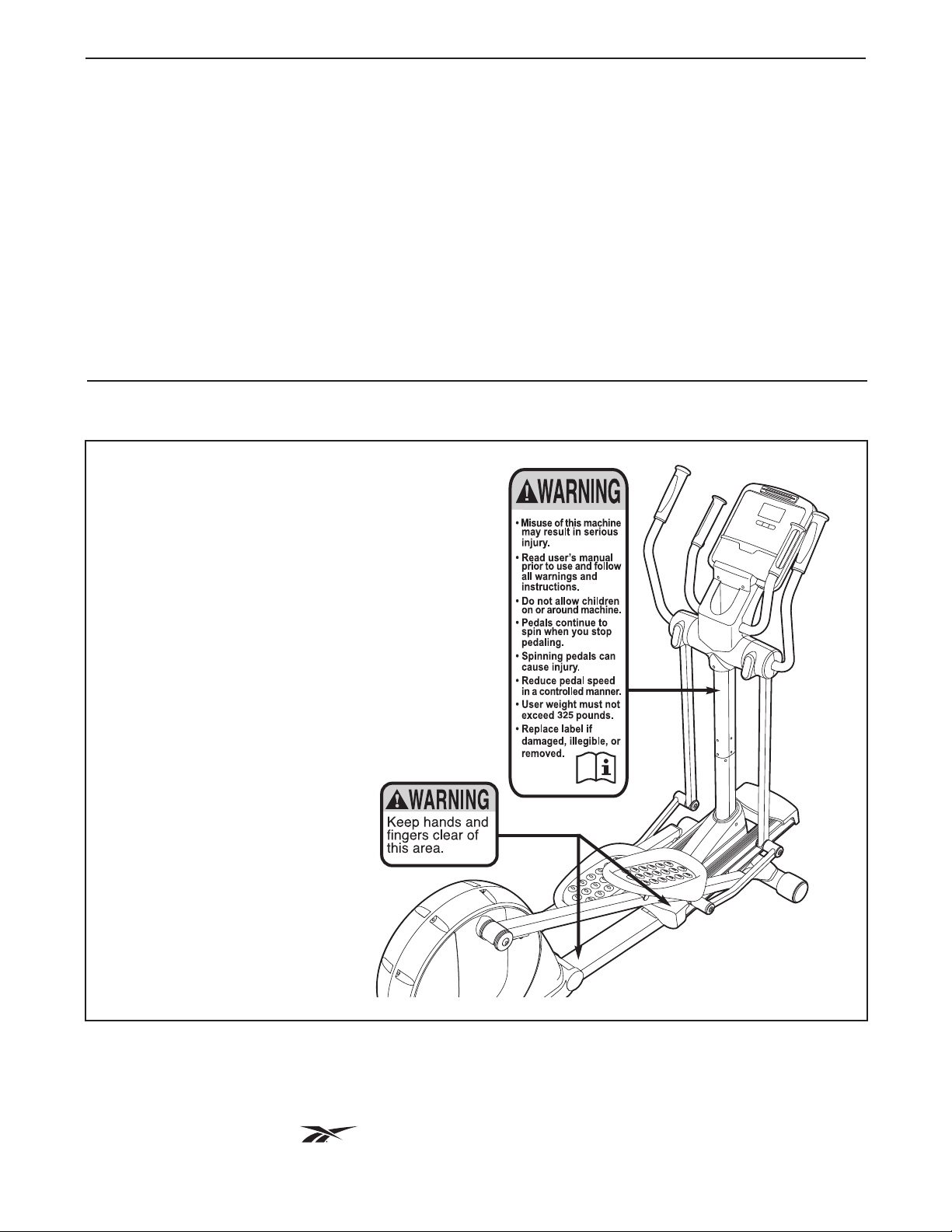
TABLE OF CONTENTS
WARNING DECAL PLACEMENT . . . . . . . . . . . . . . . . . . . . . . . . . . . . . . . . . . . . . . . . . . . . . . . . . . . . . . . . . . . . . .2
MPORTANT PRECAUTIONS . . . . . . . . . . . . . . . . . . . . . . . . . . . . . . . . . . . . . . . . . . . . . . . . . . . . . . . . . . . . . . . .3
I
BEFORE YOU BEGIN . . . . . . . . . . . . . . . . . . . . . . . . . . . . . . . . . . . . . . . . . . . . . . . . . . . . . . . . . . . . . . . . . . . . . .4
ASSEMBLY . . . . . . . . . . . . . . . . . . . . . . . . . . . . . . . . . . . . . . . . . . . . . . . . . . . . . . . . . . . . . . . . . . . . . . . . . . . . . . .5
HOW TO USE THE ELLIPTICAL EXERCISER . . . . . . . . . . . . . . . . . . . . . . . . . . . . . . . . . . . . . . . . . . . . . . . . . .11
MAINTENANCE AND TROUBLESHOOTING . . . . . . . . . . . . . . . . . . . . . . . . . . . . . . . . . . . . . . . . . . . . . . . . . . .22
EXERCISE GUIDELINES . . . . . . . . . . . . . . . . . . . . . . . . . . . . . . . . . . . . . . . . . . . . . . . . . . . . . . . . . . . . . . . . . . .23
PART LIST . . . . . . . . . . . . . . . . . . . . . . . . . . . . . . . . . . . . . . . . . . . . . . . . . . . . . . . . . . . . . . . . . . . . . . . . . . . . . .24
EXPLODED DRAWING . . . . . . . . . . . . . . . . . . . . . . . . . . . . . . . . . . . . . . . . . . . . . . . . . . . . . . . . . . . . . . . . . . . .26
ORDERING REPLACEMENT PARTS . . . . . . . . . . . . . . . . . . . . . . . . . . . . . . . . . . . . . . . . . . . . . . . . . .Back Cover
LIMITED WARRANTY . . . . . . . . . . . . . . . . . . . . . . . . . . . . . . . . . . . . . . . . . . . . . . . . . . . . . . . . . . . . . .Back Cover
WARNING DECAL PLACEMENT
The drawing shows the location(s) of the warning
decal(s). If a decal is missing or illegible, see
the front cover of this manual and request a
free replacement decal. Apply the decal in the
location shown. Note: The decal(s) may not be
shown at actual size.
REEBOK and the Vector Logo are registered trademarks and service marks of Reebok. This product is
manufactured and distributed under license from Reebok International.
2

IMPORTANT PRECAUTIONS
WARNING: To reduce the risk of serious injury, read all important precautions and
instructions in this manual and all warnings on your elliptical exerciser before using your elliptical
exerciser. ICON assumes no responsibility for personal injury or property damage sustained by or
through the use of this product.
1. Before beginning any exercise program,
consult your physician. This is especially
important for persons over age 35 or persons with pre-existing health problems.
2. Use the elliptical exerciser only as described
in this manual.
3. It is the responsibility of the owner to ensure
that all users of the elliptical exerciser are
adequately informed of all precautions.
4. The elliptical exerciser is intended for
home use only. Do not use the elliptical exerciser in a commercial, rental, or institutional
setting.
5. Keep the elliptical exerciser indoors, away
from moisture and dust. Place the elliptical
exerciser on a level surface, with a mat
beneath it to protect the floor or carpet.
Make sure that there is at least 3 ft. (0.9 m) of
clearance in the front and rear of your elliptical exerciser and 2 ft. (0.6 m) on each side.
6. Inspect and properly tighten all parts regu-
larly. Replace any worn parts immediately.
8. The elliptical exerciser should not be used
by persons weighing more than 325 lbs.
(147 kg).
9. Wear appropriate clothes while exercising;
do not wear loose clothes that could become
caught on the elliptical exerciser. Always
wear athletic shoes for foot protection while
exercising.
10. Hold the handlebars or the upper body arms
when mounting, dismounting, or using the
elliptical exerciser.
11. The pulse sensor is not a medical device.
Various factors may affect the accuracy of
heart rate readings. The pulse sensor is
intended only as an exercise aid in determining heart rate trends in general.
12. Keep your back straight while using the
elliptical exerciser; do not arch your back.
13. Over exercising may result in serious injury
or death. If you feel faint or if you experience
pain while exercising, stop immediately and
cool down.
7. Keep children under age 12 and pets away
from the elliptical exerciser at all times.
14. When you stop exercising, allow the pedals
to slowly come to a stop.
3
BEFORE YOU BEGIN
Thank you for selecting the revolutionary REEBOK
SPACESAVER RL elliptical exerciser. The SPACE-
AVER RL elliptical exerciser provides an impressive
S
selection of features designed to make your workouts
at home more effective and enjoyable.
For your benefit, read this manual carefully before
you use the elliptical exerciser. If you have ques-
tions after reading this manual, please see the front
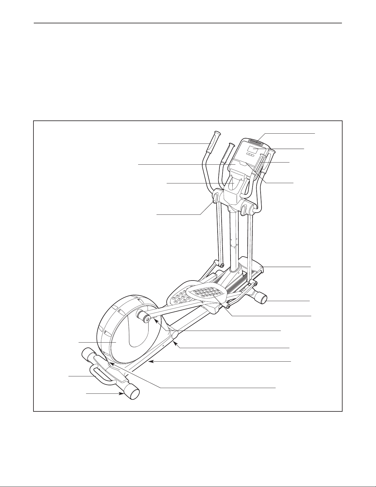
Upper Body Arm
Speakers
Water Bottle Holder
(No water bottle is
included)
Storage Magnet
®
cover of this manual. To help us assist you, note the
product model number and serial number before con-
acting us. The model number and the location of the
t
serial number decal are shown on the front cover of
this manual.
Before reading further, please familiarize yourself with
the parts that are labeled in the drawing below.
Fan
Console
Pulse Sensor
Audio Cable
Pedal Disc
Handle
Leveling Foot
Ramp
Wheel
Pedal
Pedal Arm Latch
Leveling Foot
Latch Button
Power Receptacle
4
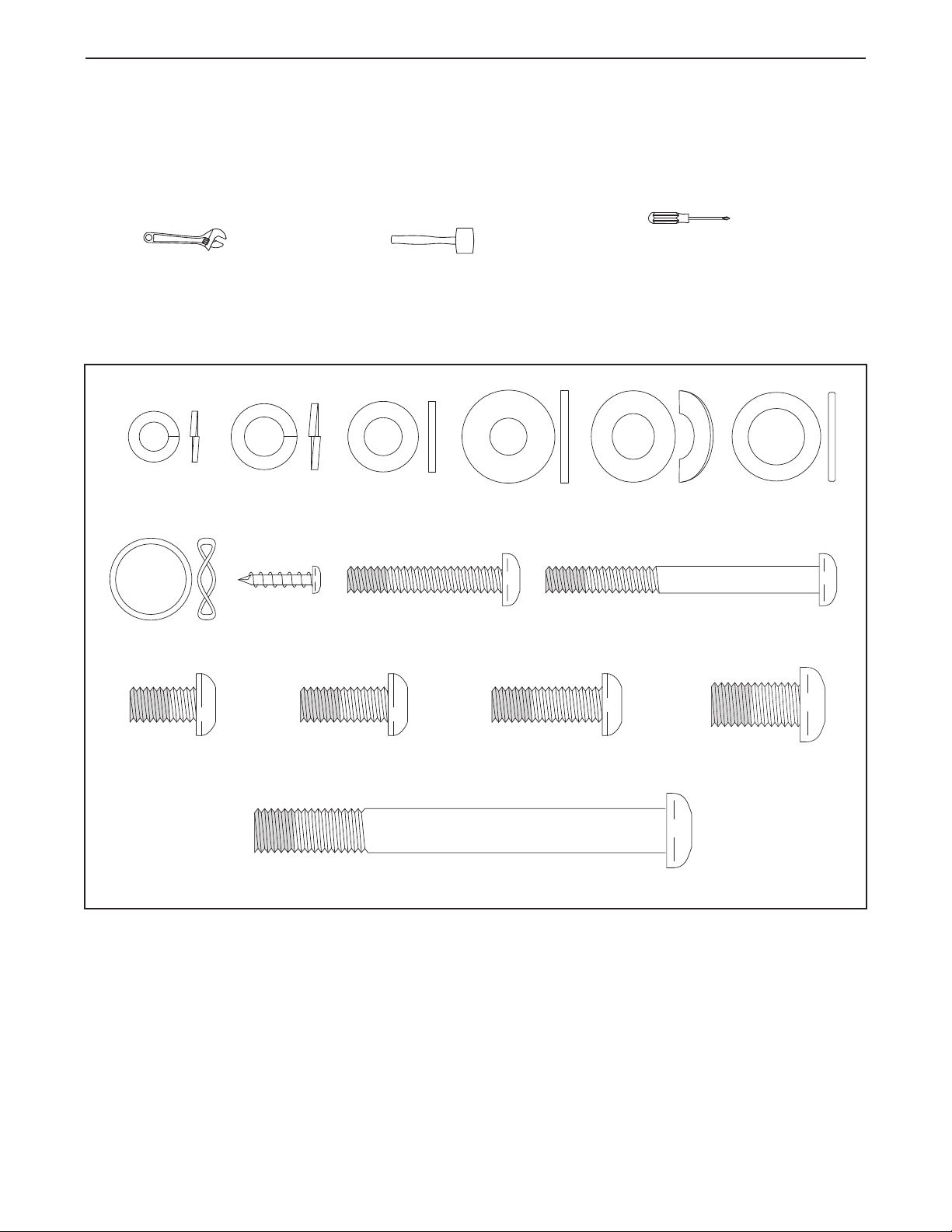
M10 x 93mm Patch Screw (82)–4
M10 x 25mm
Washer (87)–2
M8 Split
Washer (101)–4
M4 x 16mm
Screw (116)–16
M6 Split Washer
(102)–8
M6 x 35mm Patch
Screw (109)–4
M6 x 62mm Patch
Screw (108)–4
M8 x 16mm
Washer (103)–6
Link Arm
Spacer (74)–4
M8 x 20mm Patch
Screw (107)–4
M8 x 25mm Patch
Screw (110)–2
M10 x 20mm Patch
Screw (111)–2
M8 x 15mm Patch
Screw (106)–10
M10 Curved
Washer (99)–4
Wave Washer
(100)–2
ASSEMBLY
To hire an authorized service technician to assemble the elliptical exerciser, call 1-800-445-2480.
ssembly requires two persons. Place all parts of the elliptical exerciser in a cleared area and remove the
A
packing materials. Do not dispose of the packing materials until assembly is completed.
In addition to the included tool(s), assembly requires a Phillips screwdriver , an adjustable
wrench , and a rubber mallet .
As you assemble the elliptical exerciser, use the drawings below to identify small parts. The number in parentheses
below each drawing is the key number of the part, from the PART LIST near the end of this manual. The number
following the parentheses is the quantity needed for assembly. Note: If a part is not in the hardware kit, check
to see if it has been preassembled.
5
1.
To make assembly easier, read the
nformation on page 5 before you begin.
i
1
If there is a shipping bracket attached to the
rear of the Folding Frame (not shown), remove
he screw and the shipping bracket from the
t
Folding Frame. Discard the screw and the shipping bracket.
See HOW TO FOLD AND UNFOLD THE
ELLIPTICAL EXERCISER on page 11 and
unfold the elliptical exerciser.
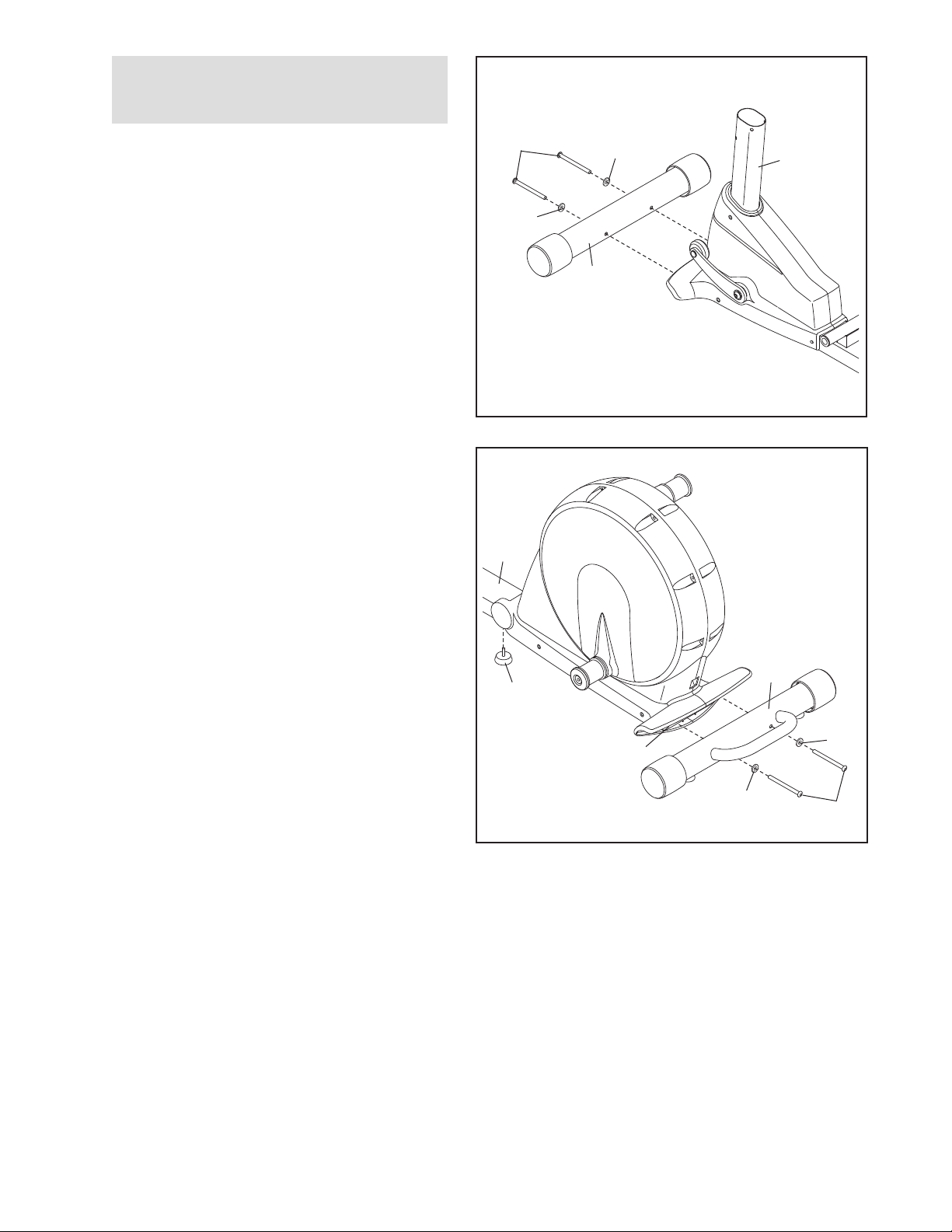
While another person lifts the front of the
Frame (1), attach the Front Stabilizer (4) to the
Frame with two M10 x 93mm Patch Screws (82)
and two M10 Curved Washers (99).
2. While another person lifts the Folding Frame
(2), attach the Rear Stabilizer (3) to the Folding
Frame with two M10 x 93mm Patch Screws (82)
and two M10 Curved Washers (99).
Next, tighten the Center Foot (95) into the
Frame (1).
82
99
2
1
99
4
1
95
3
2
99
99
82
6
3. Attach the Front Ramp Cover (6) to the
amp (5) with four M4 x 16mm Screws (116).
R
Slide an M10 x 25mm Washer (87) onto an M10
x 20mm Patch Screw (111). Tighten the Patch
Screw into one end of the Ramp Axle (72).
Apply a small amount of the included grease to
he Ramp Axle.
t
Orient the Ramp (5) as shown. Align the lower
end of the Ramp with the welded tube on the
Frame (1). Insert the Ramp Axle (72) into the
Ramp and the welded tube.
Slide an M10 x 25mm Washer (87) onto an M10
x 20mm Patch Screw (111). Tighten the Patch
Screw into the open end of the Ramp Axle (72).
3
116
6
5
87
111
4. Identify the Left Pedal (34) and the Left Pedal
Arm (32), which are marked with “Left” stickers.
Attach the Left Pedal (34) to the Left Pedal
Arm (32) with two M6 x 62mm Patch Screws
(108), two M6 x 35mm Patch Screws (109), and
four M6 Split Washers (102).
Attach the Right Pedal (not shown) to the
Right Pedal Arm (not shown) in the same
way.
72
87
111
4
32
102
109
108
Grease
34
102
109
102
1
7
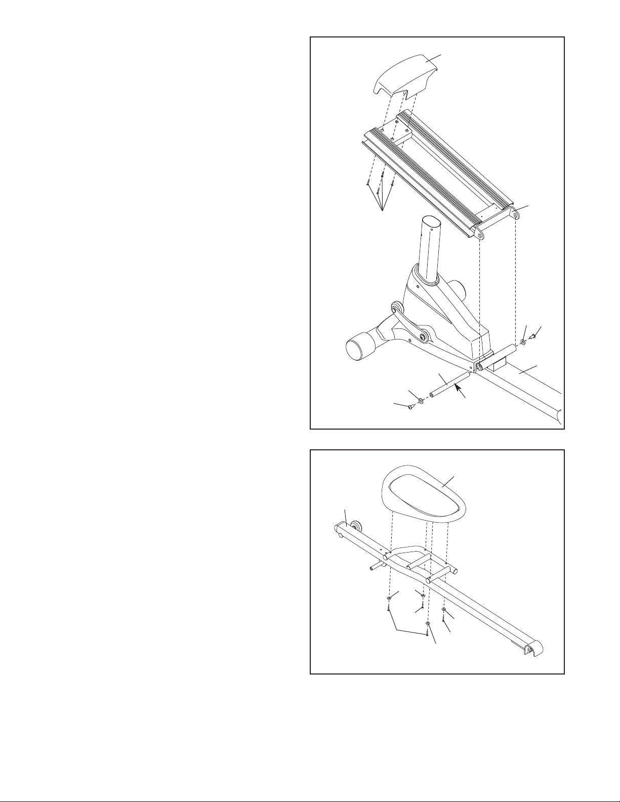
5. Insert the Roller (38) on the Left Pedal Arm (32)
and the Roller on the Right Pedal Arm (33) into
the sides of the Ramp (5).
Attach the Rear Ramp Cover (7) to the
amp (5) with two M4 x 16mm Screws (116).
R
See the inset drawing. Lift the Pedal Arm
atch (41) on the Left Pedal Arm (32) and set
L
the end of the Left Pedal Arm on the left Crank
Bushing Sleeve (54). Release the Pedal Arm
Latch; make sure that the Left Pedal Arm is
securely connected to the Crank Bushing
Sleeve.
Connect the Right Pedal Arm (33) to the
right Crank Bushing Sleeve (not shown) in
the same way.
5
16
1
33
5
32
32
7
38
6. While another person holds the Upright (10)
near the Frame (1), connect the Upper Wire
Harness (65) to the Lower Wire Harness (64).
Tip: Avoid pinching the Wire Harnesses (64,
65). Carefully insert the Upright (10) into the
Frame (1). Attach the Upright with four M8 x
20mm Patch Screws (107) and four M8 Split
Washers (101).
41
54
6
Avoid pinching the
Wire Harnesses
(64, 65)
101
10
65
107
64
101
107
1
8
. Attach the Left Upper Body Arm (22) to the left
7
Upper Body Leg (24) with three M8 x 15mm
Patch Screws (106).
ttach the Right Upper Body Arm (23) in the
A
same way.
7
3
2
22
106
24
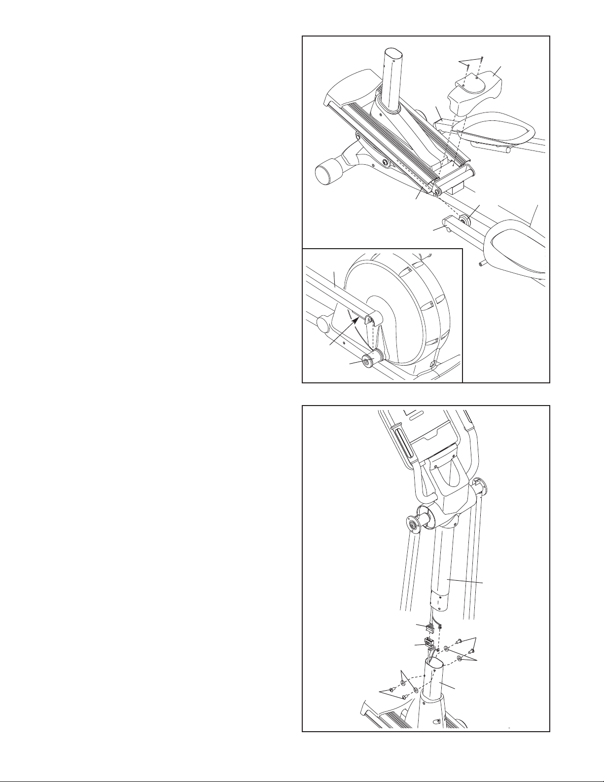
8. Hold the Left Rear Upper Body Cover (26) and
the Left Front Upper Body Cover (27) around
the left Upper Body Leg (24). Attach the Upper
Body Covers with five M4 x 16mm Screws
(116).
Attach the Right Rear Upper Body Cover
(28) and the Right Front Upper Body Cover
(29) in the same way.
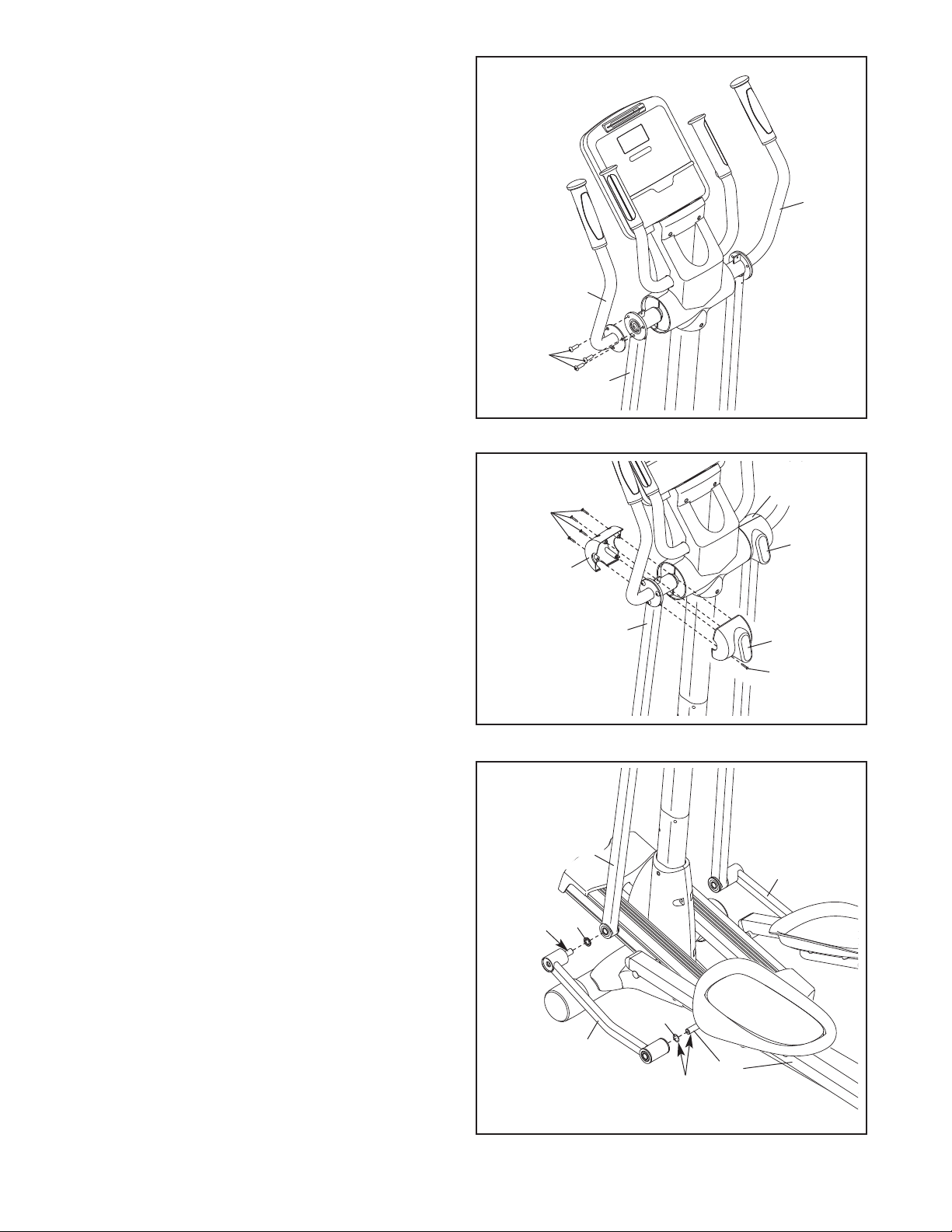
9. Apply a small amount of grease to the axle on
the Left Link Arm (30), to the axle on the Left
Pedal Arm (32), and to a Wave Washer (100).
Slide the Wave Washer (100) onto the axle on
the Left Pedal Arm (32). Next, slide a Link Arm
Spacer (74) onto the axle on the Left Link Arm
(30).
Then, gradually work the axle on the Left Link
Arm (30) into the left Upper Body Leg (24)
while at the same time working the Left Link
Arm onto the axle on the Left Pedal Arm (32).
Tip: These parts are designed to fit tightly. It
may be helpful to move the Left Pedal Arm
(32) while working these parts into place.
Repeat this step with the Right Link Arm (31).
8
9
Grease
116
27
74
24
30
24
100
Grease
29
28
26
116
31
32
9
 Loading...