

Reebok RBE09950 User Manual
Visit our website at
www.reebokhomefitness.com
new products, prizes,
fitness tips, and much more!
Patent Pending
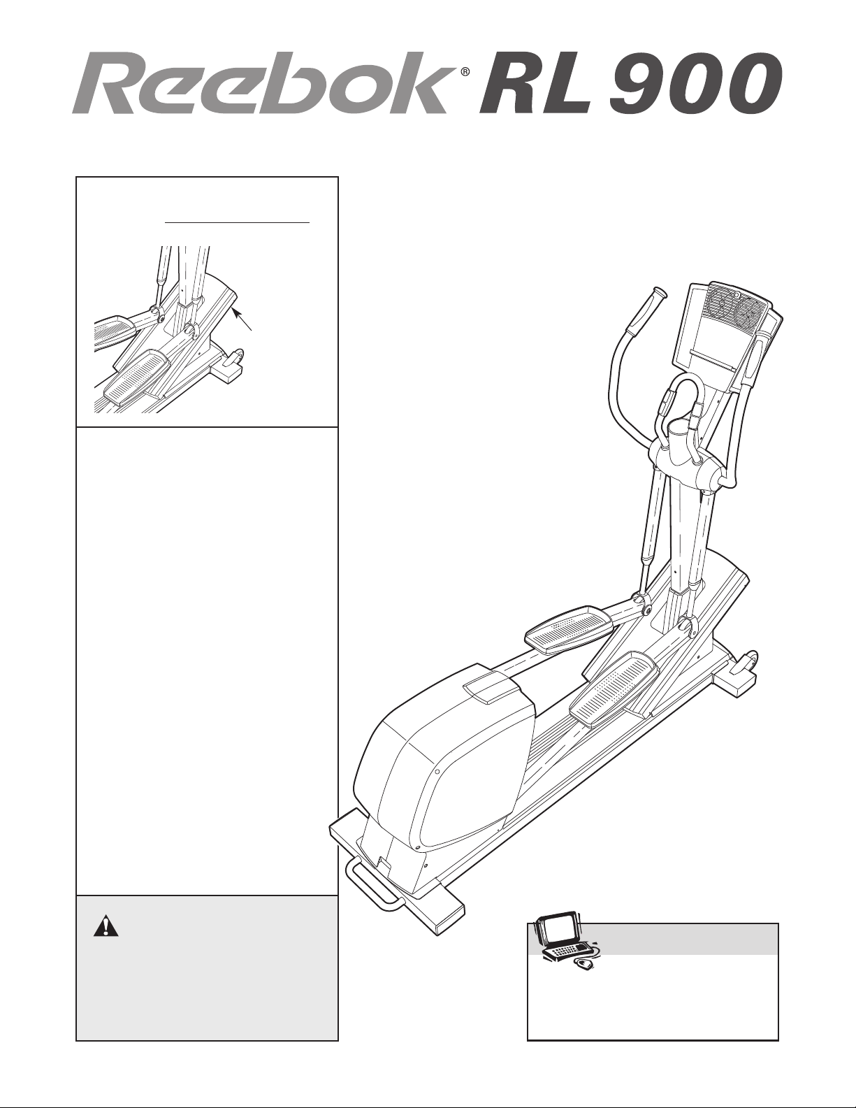
Model No. RBE09950
Serial No. _
Serial Number
Decal
(beneath
ramp)
QUESTIONS?
If you have questions, or if there
are missing parts, we will guarantee complete satisfaction
through direct assistance from
our factory.
USER’S MANUAL
TO AVOID DELAYS, PLEASE
CALL DIRECT TO OUR TOLLFREE CUSTOMER HOT LINE.
The trained technicians on our
customer hot line will provide
immediate assistance, free of
charge to you.
OMER HOT LINE:
CUST
1-877-994-4999
Mon.–Fri., 6 a.m.–6 p.m. MST
CAUTION
Read all precautions and instructions in this manual before using
this equipment. Keep this manual
for future reference.

TABLE OF CONTENTS
IMPORTANT PRECAUTIONS . . . . . . . . . . . . . . . . . . . . . . . . . . . . . . . . . . . . . . . . . . . . . . . . . . . . . . . . . . . . . . . .2
BEFORE YOU BEGIN . . . . . . . . . . . . . . . . . . . . . . . . . . . . . . . . . . . . . . . . . . . . . . . . . . . . . . . . . . . . . . . . . . . . . .3
ASSEMBLY . . . . . . . . . . . . . . . . . . . . . . . . . . . . . . . . . . . . . . . . . . . . . . . . . . . . . . . . . . . . . . . . . . . . . . . . . . . . . . .4
ELLIPTICAL EXERCISER OPERATION . . . . . . . . . . . . . . . . . . . . . . . . . . . . . . . . . . . . . . . . . . . . . . . . . . . . . . . .9
MAINTENANCE AND TROUBLESHOOTING . . . . . . . . . . . . . . . . . . . . . . . . . . . . . . . . . . . . . . . . . . . . . . . . . . .22
EXERCISE GUIDELINES . . . . . . . . . . . . . . . . . . . . . . . . . . . . . . . . . . . . . . . . . . . . . . . . . . . . . . . . . . . . . . . . . . .23
PART LIST . . . . . . . . . . . . . . . . . . . . . . . . . . . . . . . . . . . . . . . . . . . . . . . . . . . . . . . . . . . . . . . . . . . . . . . . . . . . . .24
EXPLODED DRAWING . . . . . . . . . . . . . . . . . . . . . . . . . . . . . . . . . . . . . . . . . . . . . . . . . . . . . . . . . . . . . . . . . . . .26
ORDERING REPLACEMENT PARTS . . . . . . . . . . . . . . . . . . . . . . . . . . . . . . . . . . . . . . . . . . . . . . . . . .Back Cover
LIMITED WARRANTY . . . . . . . . . . . . . . . . . . . . . . . . . . . . . . . . . . . . . . . . . . . . . . . . . . . . . . . . . . . . . .Back Cover
IMPORTANT PRECAUTIONS
WARNING:To reduce the risk of serious injury, read the following important precau-
tions before using the elliptical exerciser.
1. Read all instructions in this manual before
using the elliptical exerciser.
2. It is the responsibility of the owner to ensure
that all users of the elliptical exerciser are
adequately informed of all precautions.
3. The elliptical exerciser is intended for
in-home use only. Do not use the elliptical
exerciser in a commercial, rental, or institutional setting.
9. Wear appropriate exercise clothes when
using the elliptical exerciser. Always wear
athletic shoes for foot protection.
10. Keep your back straight when using the elliptical exerciser; do not arch your back.
11. If you feel pain or dizziness while exercising, stop immediately and begin cooling
down.
Place the elliptical exerciser on a level sur-
4.
face, with a mat beneath it to protect the
floor or carpet. Keep the elliptical exerciser
indoors, away from moisture and dust.
5. Inspect and properly tighten all parts regularly. Replace any worn parts immediately.
Keep children under age 12 and pets away
6.
from the elliptical exerciser at all times.
7. The elliptical exerciser should not be used
by persons weighing more than 350 pounds.
8. Always hold the handlebars when mounting,
dismounting, or using the elliptical exerciser
.
The pulse sensor is not a medical device.
12.
Various factors, including the user's movement, may affect the accuracy of heart rate
readings. The pulse sensor is intended only
as an exerci se aid in determining heart rate
trends in general.
13.
When you stop exercising, allow the pedals
to slowly come to a complete stop. The ellip
tical exerciser does not have a free wheel;
the pedals will continue to move until the
flywheel stops.
Always unplug the power cord immediately
14.
after use and before cleaning the elliptical
exerciser
.
WARNING:Before beginning this or any exercise program, consult your physician.
This is especially important for persons over the age of 35 or persons with pre-existing health problems. Read all instructions before using. ICON assumes no responsibility for personal injury or
property damage sustained by or through the use of this product.
2
-
BEFORE YOU BEGIN
Congratulations for selecting the new REEBOK®RL
900 elliptical exerciser. The RL 900 elliptical exerciser
is an incredibly smooth exerciser that moves your feet
in a natural elliptical path, minimizing the impact on
your knees and ankles.
cal exerciser features adjustable resistance
incline to help you get the most from your exercise.
For your benefit, read this manual carefully before
you use the elliptical exerciser. If you have ques-
tions after reading this manual, please call our
And the unique RL 900 ellipti-
and
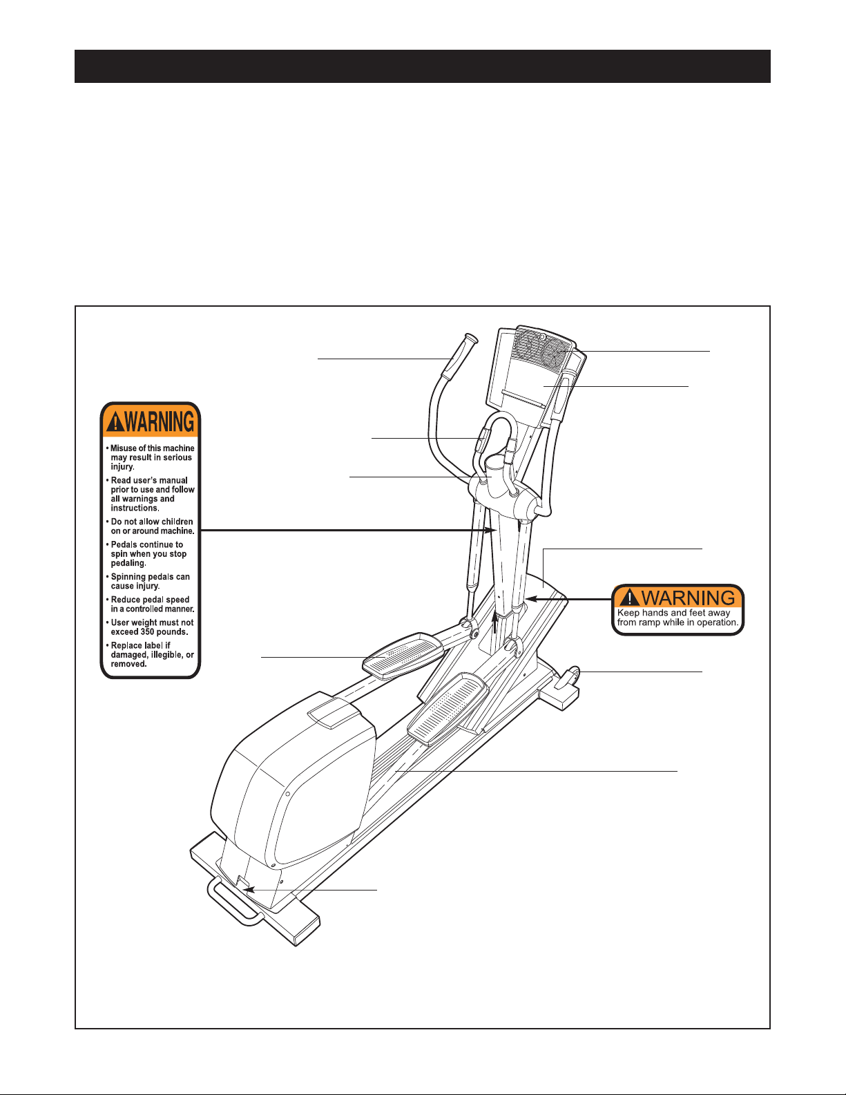
Left Handlebar
Handgrip Pulse Sensor
Water Bottle Holder*
Customer Service Department toll-free at 1-877-9944999, Monday through Friday, 6 a.m. until 6 p.m.
Mountain Time (excluding holidays). To help us assist
you, please note the product model number and serial
number before calling.
RBE09950.
decal attached to the elliptical exerciser (see the front
cover of this manual for the location of the decal).
Before reading further, please familiarize yourself with
the parts that are labeled in the drawing below.
The serial number can be found on a
The model number is
Fans
Console
BACK
Ramp
Pedal
Wheel
Pedal Arm
RIGHT SIDE
Power Receptacle
*No water bottle is included
The decals shown above have been placed on the elliptical exerciser
illegible, please call our Customer Service Department toll-free at 1-877-994-4999 and order a free
replacement decal. Apply the decal in the location shown.
. If either decal is missing or
3
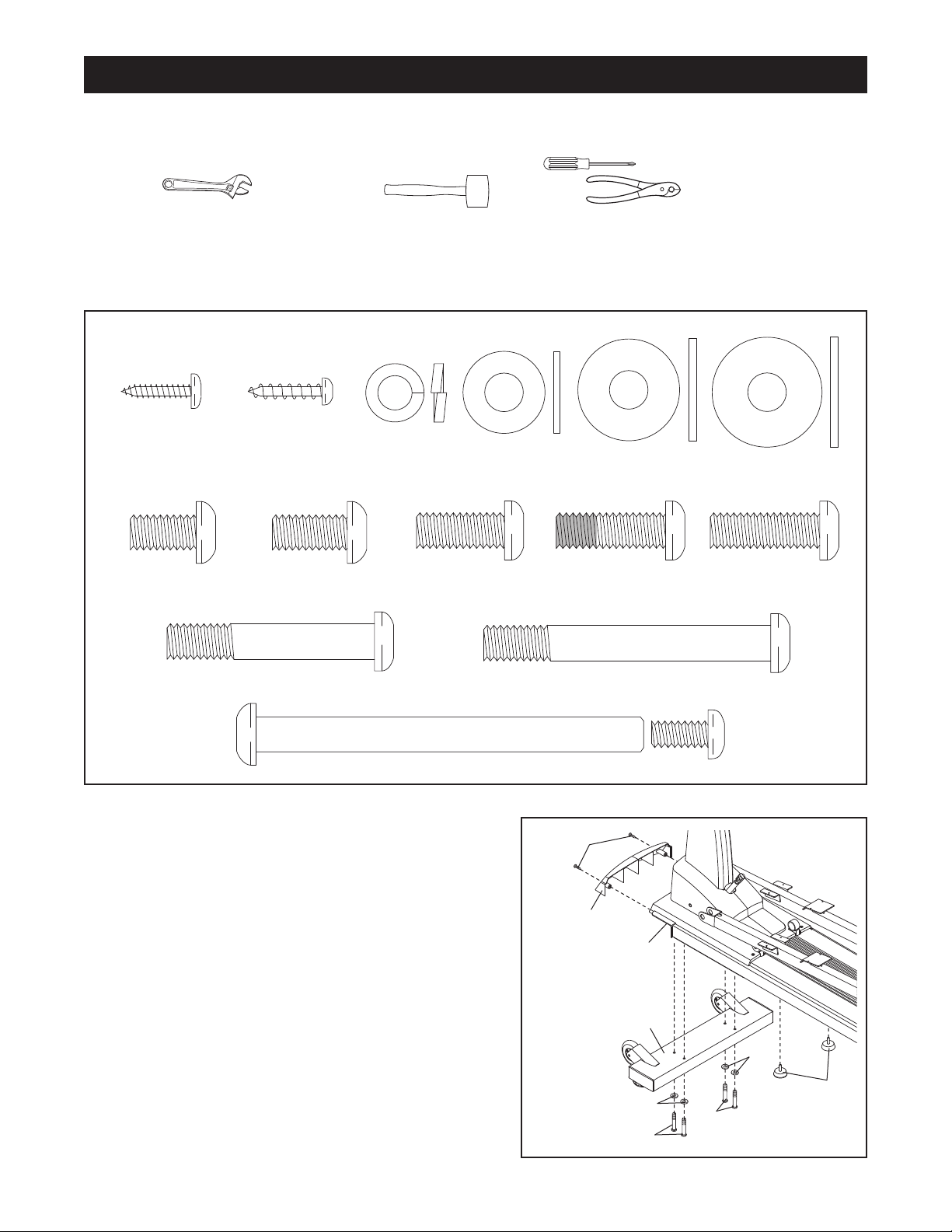
M8 Split
Washer
(85)–11
M8 x 25mm
Washer (119)–2
M8 x 18mm
Washer (93)–4
M8 x 20mm Button
Screw (118)–2
M8 x 25mm Button
Screw (100)–1
M8 x 65mm Button Screw (95)–8
M8 x 47mm Button Screw (1 10)–2
M8 x 23mm
Washer (103)–2
Union Set (86)–2
M4 x 16mm
Screw (89)–30
M4 x 16mm Round
Head Screw (91)–6
M8 x 13mm Button
Screw (90)–8
M8 x 16mm Button
Screw (94)–4
M8 x 25mm Patch
Screw (123)–2
ASSEMBLY
Assembly requires two persons. Place all parts of the elliptical exerciser in a cleared area and remove the
packing materials. Do not dispose of the packing materials until assembly is completed. In addition to the two
included hex keys, assembly requires a phillips screwdriver , two adjustable
wrenches , a rubber mallet
Use the drawings below to identify the small parts used for assembly. The number in parenthesis below each
drawing is the key number of the part, from the PART LIST on pages 24 and 25. The number following the key
number is the quantity needed for assembly. Note: Some sm all par ts may have been pre-assembled. If a part
is not in the parts bag, check to see if it has been pre-assembled.
, and pliers .
Orient the Front Stabilizer (3) as shown.
1.
Front Stabilizer to the Frame (1) with four M8 x 65mm
Button Screws (95) and four M8 Split Washers (85).
Next, attach the Front Shield (38) to the Front
Stabilizer (3) with two M4 x 16mm Round Head
Screws (91).
Then, tighten the two Frame Cushions (106) into the
underside of the Frame (1).
Attach the
1
91
38
4
1
3
85
95
95
85
106
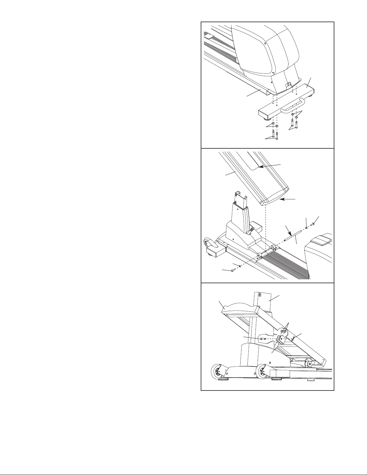
2. Orient the Rear Stabilizer (2) as shown. Attach the
Rear Stabilizer to the Frame (1) with four M8 x 65mm
Button Screws (95) and four M8 Split W
ashers (85).
2
2
1
85
3. Slide an M8 x 25mm Washer (119) onto an M8 x
20mm Button Screw (118). Tighten the Button Screw
into one end of the Incline Axle (68). Apply a small
amount of the included grease to the Incline
Orient the Ramp (5) so that the opening is up as
shown. Fit the welded tube on the underside of the
Ramp between the two rings on the top of the Frame
(1). Insert the Incline Axle (68) through the rings and
the welded tube.
Slide an M8 x 25mm Washer (119) onto an M8 x
20mm Button Screw (118). Tighten the Button Screw
into the open end of the Incline Axle (68).
4. Using your fingers, turn the shaft on top of the Motor
(46) counterclockwise until it stops turning. Next, fit the
opening of the Ramp (5) over the front of the Frame
(1) as shown. Position the U-bracket on the underside
of the Ramp over the end of the shaft as shown.
Insert the Clevis Pin (112) through one side of the Ubracket on the Ramp (5), an 8mm Plastic Spacer
(111), the shaft on the Motor (46), another 8mm Plastic
Spacer, and the other side of the U-bracket. Then,
insert the straight end of a Hairpin (65) through the
hole in the Clevis Pin.
Axle.
85
95
3
5
119
118
4
5
12
1
46
95
Opening
Grease
1
111
Welded
Tube
119
68
65
118
5
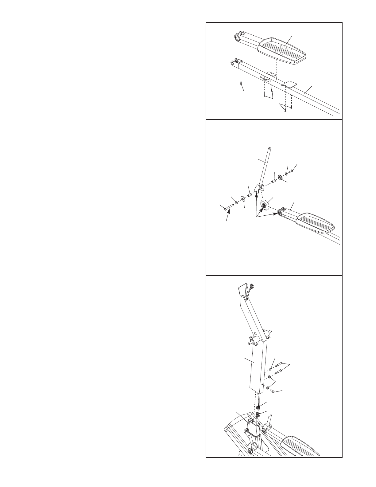
5. Attach a Pedal Assembly (39) to the Left Pedal Arm (9)
with five M4 x 16mm Screws (89).
Attach the other Pedal Assembly (not shown) to the
Right Pedal
Arm (not shown) in the same way.
5
89
89
39
9
6. Remove the two Pivot Shafts (10) from the two Pivot
Arms (not shown). Next, identify a Union Set (86), and
remove t he scr ew fro m the barrel. Apply a small
amount of grease to the outside of the barrel.
Slide an M8 x 18mm Washer (93), a Wheel Cap (53),
and a 30mm Spacer (87) onto the barrel of the Union
Set (86). While another person aligns the indicated
holes in the Left Pedal Assembly (39), a Pedal Arm
Wheel (52), and a Pivot Shaft (10), insert the barrel
through all of the holes. Then, slide another 30mm
Spacer (87) onto the barrel.
Next, slide an M8 x 18mm Washer (93) and a Wheel
Cap (53) onto the screw of the Union Set (86), and
tighten the screw into the barrel.
Attach the other Pivot Shaft (not shown) and the other
Pedal Arm Wheel (not shown) to the Right Pedal
Assembly (not shown) in the same way.
7. While another person holds the Upright (4) near the
Frame (1), connect the Upper Wire Harness (58) to the
Extension Wire Harness (59). Slide the Upright onto
the top of the Frame, being careful not to pinch the
ire Harnesses
W
Attach the Upright (4) to the Frame (1) with two M8 x
47mm Button Screws (110), an M8 x 25mm Button
Screw (100), and three M8 Split Washers (85).
.
6
86
Grease
7
93
87
53
Align
these
holes
10
86
93
87
53
52
39
Do not pinch the
wire harnesses
during this step.
58
59
85
85
100
10
1
4
1
6
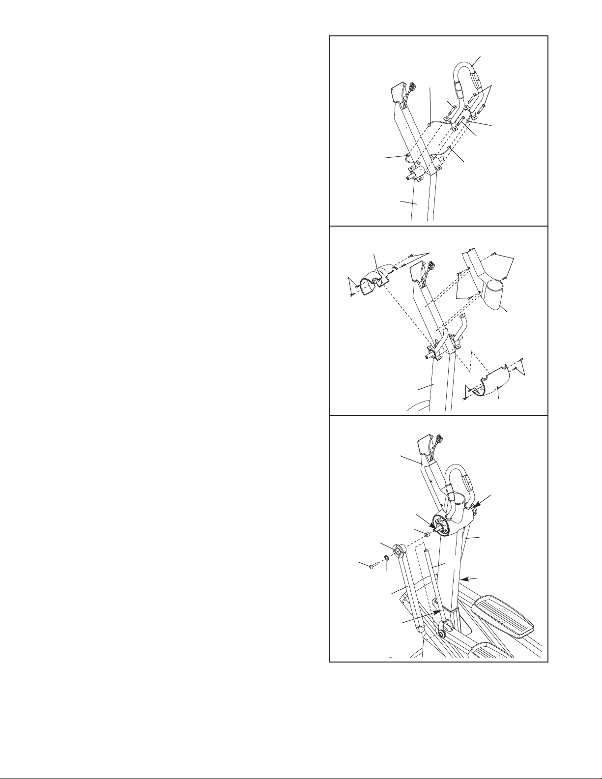
While another person holds the Pulse Sensor Bar (26)
8.
near the Upright (4), connect the upper pulse wires to
the lower pulse wires. Insert the excess wire into the
Upright.
Orient the Pulse Sensor Bar (26) as shown. Attach the
Pulse Sensor Bar to the Upright (4) with four M8 x
16mm Button Screws (94),
pinch the wires.
being careful not to
8
Lower
Pulse Wire
26
Upper
Pulse
Wire
94
Pulse Wire
4
94
Upper
Pulse Wire
94
Lower
9. Identify the Front Center Pivot Cover (27). Attach the
Front Center Pivot Cover to the Frame (1) with four M4
x 16mm Screws (89).
Next, identify the Rear Center Pivot Cover (28). Attach
the Rear Center Pivot Cover to the Frame (1) with four
M4 x 16mm Screws (89).
Attach the Water Bottle Holder (23) to the Upright (4)
with four M4 x 16mm Screws (89).
10.Apply a small amount of the included Teflon®lubricant
to a paper towel, and rub a thin film of the lubricant
onto both of the Pivot Shafts (10). Next, apply a small
amount of grease to the axle in the Upright (4).
Then, slide a 5mm Spacer (35) onto each end of the
axle in the Upright (4).
Next, slide the two Pivot Arms (20) onto the Pivot
Shafts (10), and turn the Pivot Arms so the flanges are
facing away from the elliptical exerciser. Then, slide
the Pivot Arms onto the ends of the axle in the Upright
(4); use a rubber mallet, if necessary.
Slide an M8 x 23mm Washer (103) onto an M8 x
25mm Patch Screw (123). Attach the left Pivot Arm
(20) to the left end of the axle with the Patch Screw.
Attach the right Pivot
axle in the same way.
Arm (20) to the right end of the
9
89
10
123
28
Flange
103
20
Lubricate
4
4
Grease
35
89
89
10
89
89
23
89
27
Grease
20
10
7
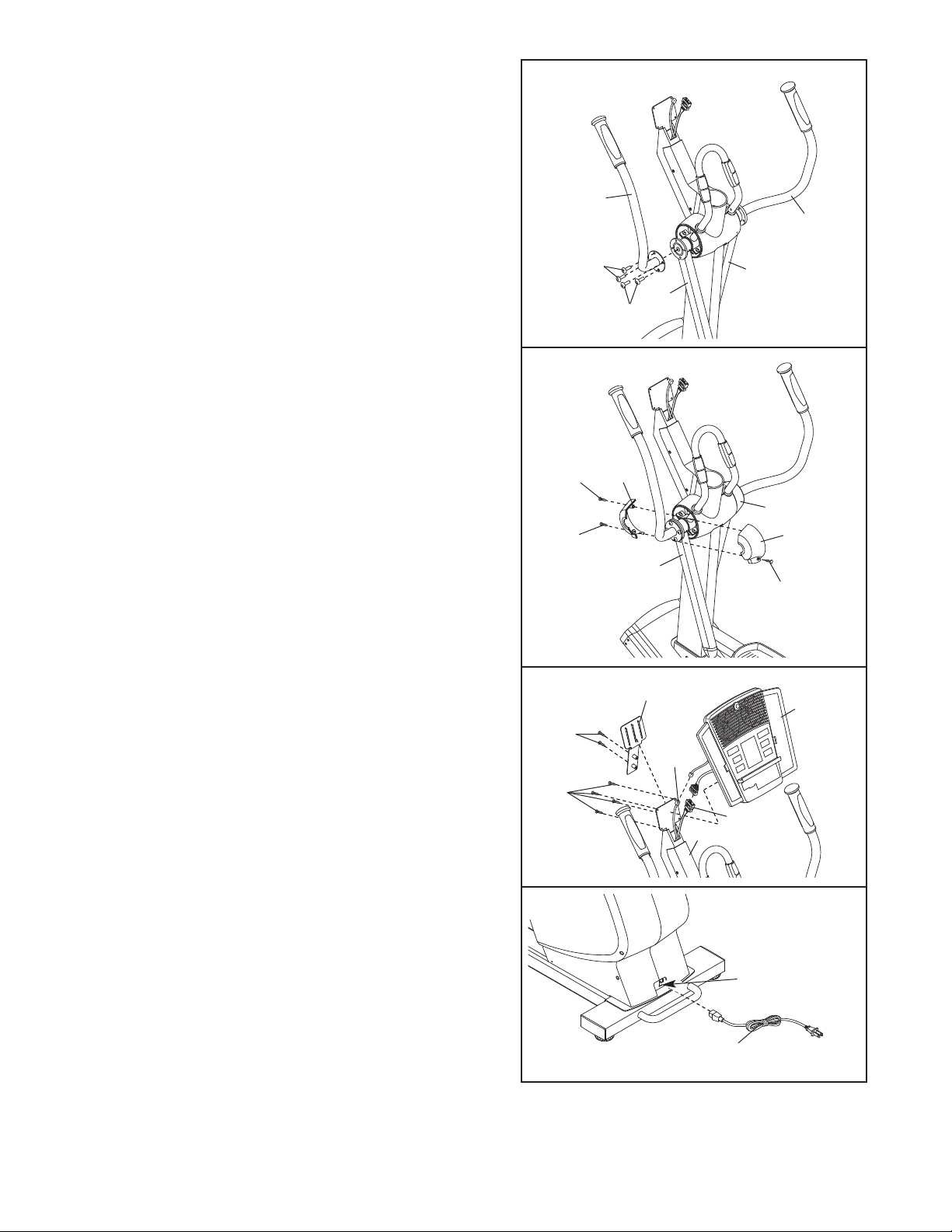
11.Identify the Left Handlebar (7). Attach the Left
Handlebar to the left Pivot Arm (20) with four M8 x
13mm Button Screws (90) as shown.
Attach the Right Handlebar (6) to the right Pivot Arm
(20) in the same way.
1
1
7
6
12.Position the Front Left Pivot Cover (21) and the Rear
Left Pivot Cover (31) over the left Pivot Arm (20) as
shown. Attach the Left Pivot Covers with an M4 x
16mm Round Head Screw (91) and two M4 x 16mm
Screws (89).
Attach the Front Right Pivot Cover (29) and the Rear
Right Pivot Cover (not shown) over the right Pivot Arm
(not shown) in the same way.
13. While another person holds the Console (17) near the
Upright (4), attach the Upper Wire Harness (58) and
the Pulse Sensor Wire (25) to the corresponding console wire harnesses. Then, attach the Console to the
Upright with four M4 x 16mm Screws (89), being
careful not to pinch the wires.
Attach the Upright Cover (22) to the Upright (4) with
two M4 x 16mm Round Head Screws (91).
12
13
89
89
91
91
90
31
90
20
22
20
20
29
21
89
17
25
58
4
14. Plug the Power Cord (56) into the Power Receptacle
(70) at the rear of the elliptical exerciser.
15.Make sure that all parts of the elliptical exerciser are properly tightened. Cover the floor beneath the
elliptical exerciser to protect the floor from damage. Note: Some extra hardware may be left over.
14
70
56
8
ELLIPTICAL EXERCISER OPERATION
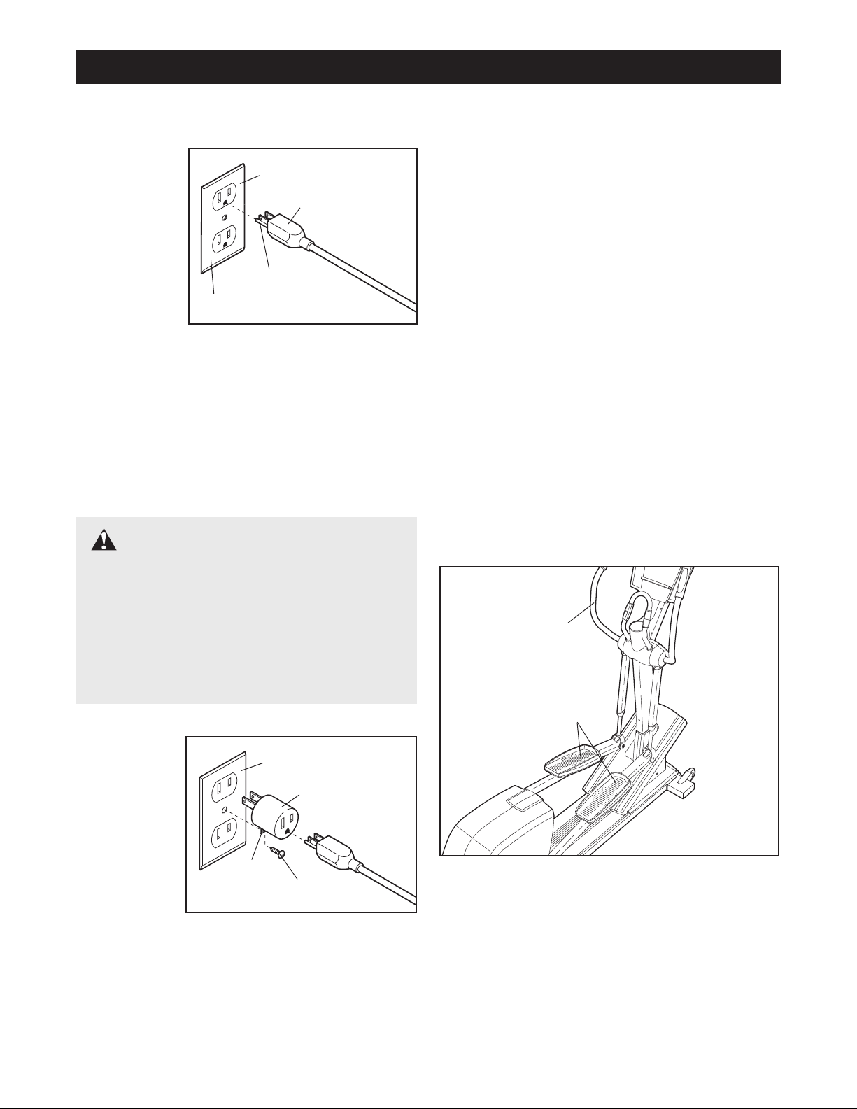
HOW TO PLUG IN THE POWER CORD
This product
must be
grounded.
If it should
malfunction
or break
down,
grounding
provides a
path of least
resistance for
electric
current to reduce the risk of electric shock. This product is equipped with a cord having an equipmentgrounding conductor and a grounding plug.
power cord into an appropriate outlet that is properly installed and grounded in accordance with all
local codes and ordinances. This product is for
use on a nominal 120-volt circuit. Important: The
elliptical exerciser is not compatible with GFCIequipped outlets.
Grounded Outlet
Grounded Outlet Box
Grounding Plug
Grounding Pin
Plug the
DANGER:Improper connection of
the equipment-grounding conductor can result
in an increased risk of electric shock. Check
with a qualified electrician or serviceman if
you are in doubt as to whether the product is
properly grounded. Do not modify the plug
provided with the product—if it will not fit the
outlet, have a proper outlet installed by a qualified electrician.
The green-colored rigid ear, lug, or the like extending
from the adapter must be connected to a permanent
ground such as a properly grounded outlet box cover.
Whenever the adapter is used, it must be held in
place by a metal screw.
let box covers are not grounded. Contact a quali
fied electrician to determine if the outlet box cover
is grounded before using an adapter.
Note: When the power cord is plugged in, the elliptical exerciser’s incline system may automatically
calibrate itself. During the calibration process, two
dashes (– –) will appear in the Ramp display
while the ramp rises to the highest position and
then moves down to the lowest position. The calibration process may last for one to two minutes. If
the incline system does not calibrate itself, see
HOW TO CALIBRATE THE INCLINE SYSTEM on
page 22.
EXERCISING ON THE ELLIPTICAL EXERCISER
To mount the elliptical exerciser, hold the handlebars
and step onto the pedal that is in the lowest position.
Next, step onto the other pedal. Push the pedals until
they begin to move with a continuous motion.
Handlebar
Some 2-pole receptacle out-
-
A temporary
adapter may
be used to
connect the
power cord
to a 2-pole
receptacle
as shown at
the right if a
properly
grounded
outlet is not
available. The temporary adapter should be used only
until a properly grounded outlet can be installed by a
qualified electrician.
Grounded Outlet Box
Adapter
Lug
Metal Screw
Pedals
o dismount the elliptical exerciser
T
als come to a complete stop.
does not have a free wheel; the pedals will contin
ue to move until the flywheel stops. When the ped
als are stationary, step off the highest pedal first.
Then, step of
f the lowest pedal.
, wait until the ped
The elliptical exerciser
9
-
-
-
 Loading...