

Reebok RBCCEX149100 Owner's Manual
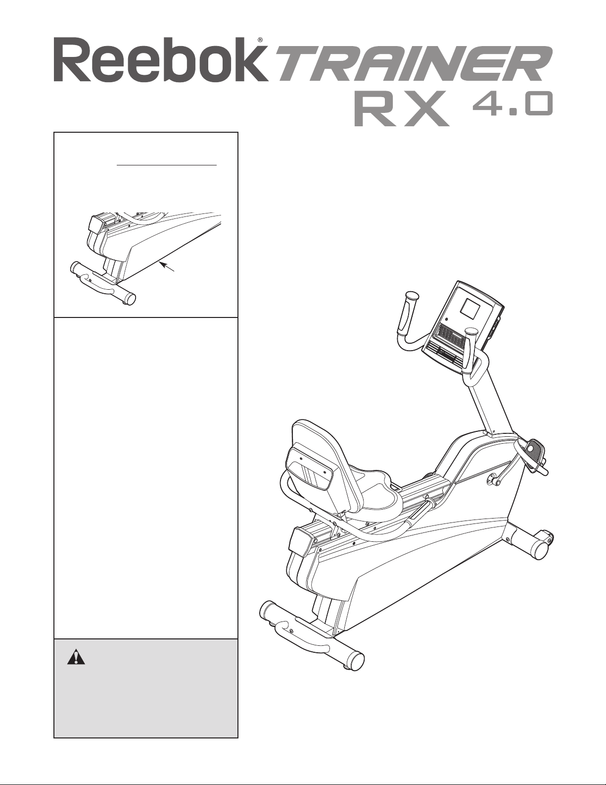
Model No. RBCCEX14910.0
Serial No.
Write the serial number in the
space above for reference.
Serial
Number
Decal
QUESTIONS?
If you have questions, or if parts are
damaged or missing, PLEASE
CONTACT OUR CUSTOMER SERVICE DEPARTMENT DIRECTLY.
CALL TOLL-FREE:
USER'S MANUAL
1-888-936-4266
Mon.–Fri., 7:30 until 16:30 ET
(excluding holidays)
OR E-MAIL US:
customerservice@iconcanada.ca
CAUTION
Read all precautions and instructions in this manual before using
this equipment. Keep this manual
for future reference.
www.reebokfitness.com
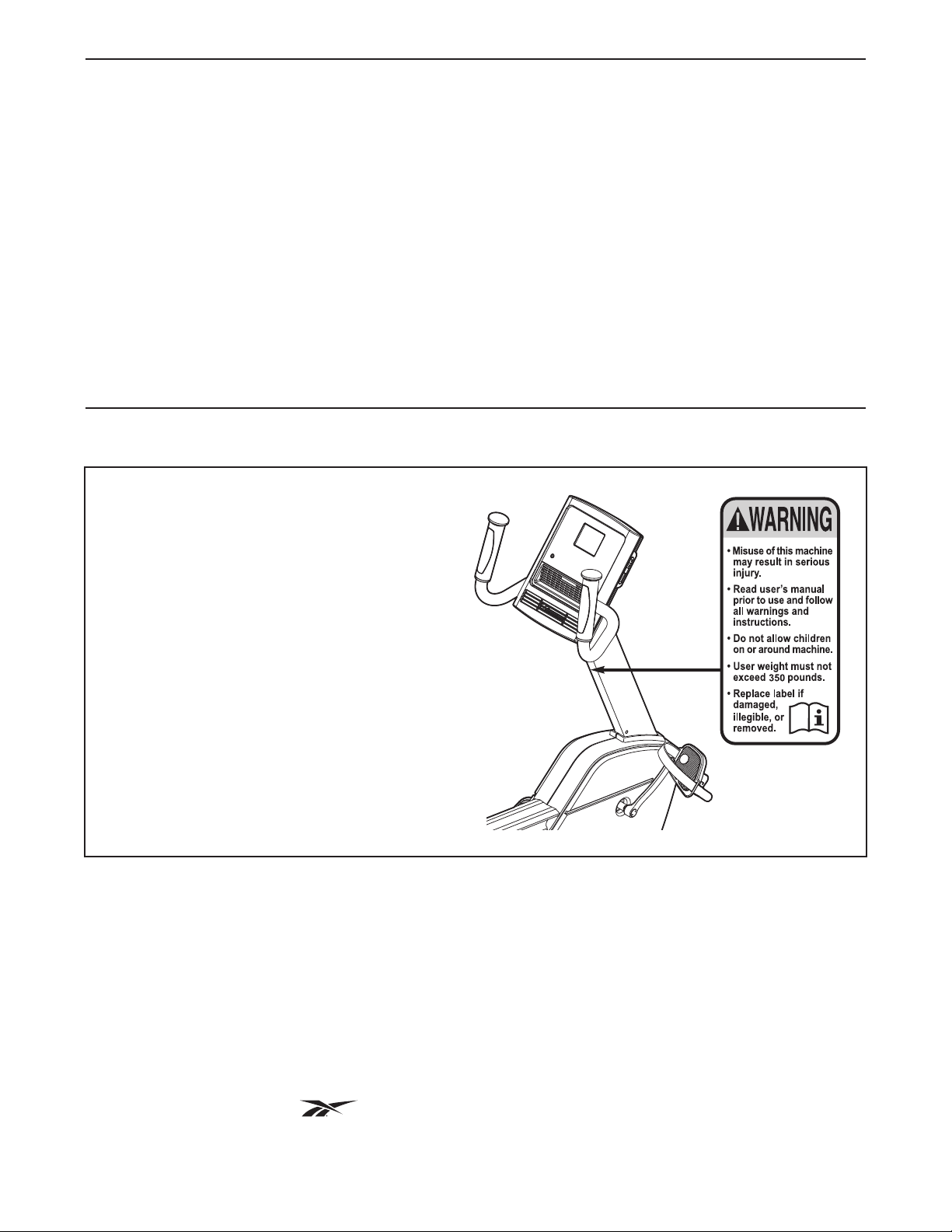
TABLE OF CONTENTS
WARNING DECAL PLACEMENT . . . . . . . . . . . . . . . . . . . . . . . . . . . . . . . . . . . . . . . . . . . . . . . . . . . . . . . . . . . . . .2
IMPORTANT PRECAUTIONS . . . . . . . . . . . . . . . . . . . . . . . . . . . . . . . . . . . . . . . . . . . . . . . . . . . . . . . . . . . . . . . .3
EFORE YOU BEGIN . . . . . . . . . . . . . . . . . . . . . . . . . . . . . . . . . . . . . . . . . . . . . . . . . . . . . . . . . . . . . . . . . . . . . .4
B
ASSEMBLY . . . . . . . . . . . . . . . . . . . . . . . . . . . . . . . . . . . . . . . . . . . . . . . . . . . . . . . . . . . . . . . . . . . . . . . . . . . . . . .5
HOW TO USE THE EXERCISE BIKE . . . . . . . . . . . . . . . . . . . . . . . . . . . . . . . . . . . . . . . . . . . . . . . . . . . . . . . . .11
MAINTENANCE AND TROUBLESHOOTING . . . . . . . . . . . . . . . . . . . . . . . . . . . . . . . . . . . . . . . . . . . . . . . . . . .17
EXERCISE GUIDELINES . . . . . . . . . . . . . . . . . . . . . . . . . . . . . . . . . . . . . . . . . . . . . . . . . . . . . . . . . . . . . . . . . . .18
PART LIST . . . . . . . . . . . . . . . . . . . . . . . . . . . . . . . . . . . . . . . . . . . . . . . . . . . . . . . . . . . . . . . . . . . . . . . . . . . . . .20
EXPLODED DRAWING . . . . . . . . . . . . . . . . . . . . . . . . . . . . . . . . . . . . . . . . . . . . . . . . . . . . . . . . . . . . . . . . . . . .22
ORDERING REPLACEMENT PARTS . . . . . . . . . . . . . . . . . . . . . . . . . . . . . . . . . . . . . . . . . . . . . . . . . .Back Cover
LIMITED WARRANTY . . . . . . . . . . . . . . . . . . . . . . . . . . . . . . . . . . . . . . . . . . . . . . . . . . . . . . . . . . . . . .Back Cover
WARNING DECAL PLACEMENT
This drawing shows the location(s) of the
warning decal(s). If a decal is missing or
illegible, see the front cover of this
manual and request a free replacement
decal. Apply the decal in the location
shown. Note: The decal(s) may not be
shown at actual size.
REEBOK and the Vector Logo are registered trademarks and service marks of Reebok. This product is
manufactured and distributed under license from Reebok International. iPod is a trademark of Apple Computer,
Inc., registered in the U.S. and other countries. iPod®is not included.
2

IMPORTANT PRECAUTIONS
WARNING: To reduce the risk of serious injury, read all important precautions and
instructions in this manual and all warnings on your exercise bike before using your exercise bike.
CON assumes no responsibility for personal injury or property damage sustained by or through the
I
use of this product.
1. Before beginning any exercise program,
consult your physician. This is especially
important for persons over age 35 or persons with pre-existing health problems.
2. Use the exercise bike only as described in
this manual.
3. It is the responsibility of the owner to ensure
that all users of the exercise bike are adequately informed of all precautions.
4. The exercise bike is intended for home use
only. Do not use the exercise bike in a commercial, rental, or institutional setting.
5. Keep the exercise bike indoors, away from
moisture and dust. Do not put the exercise
bike in a garage or covered patio, or near
water.
6. Place the exercise bike on a level surface
with at least 2 ft. (0.6 m) of clearance around
the exercise bike. To protect the floor or
carpet from damage, place a mat under the
exercise bike.
8. Keep children under age 12 and pets away
from the exercise bike at all times.
9. The exercise bike should not be used by
persons weighing more than 350 lbs.
(159 kg).
10. Wear appropriate clothes while exercising;
do not wear loose clothes that could become
caught on the exercise bike. Always wear
athletic shoes for foot protection.
11. The pulse sensor is not a medical device.
Various factors, including the user's movement, may affect the accuracy of heart rate
readings. The pulse sensor is intended only
as an exercise aid in determining heart rate
trends in general.
12. Always keep your back straight while using
the exercise bike; do not arch your back.
13. Over exercising may result in serious injury
or death. If you feel faint or if you experience
pain while exercising, stop immediately and
cool down.
7. Inspect and properly tighten all parts regularly. Replace any worn parts immediately.
14. This Class [B] digital apparatus complies
with Canadian ICES-003.
3
BEFORE YOU BEGIN
hank you for selecting the revolutionary REEBOK
T
TRAINER RX 4.0 exercise bike. Cycling is an effective
exercise for increasing cardiovascular fitness, building
endurance, and toning the body. The TRAINER RX
.0 exercise bike provides an impressive selection of
4
features designed to make your workouts at home
more effective and enjoyable.
For your benefit, read this manual carefully before
you use the exercise bike. If you have questions
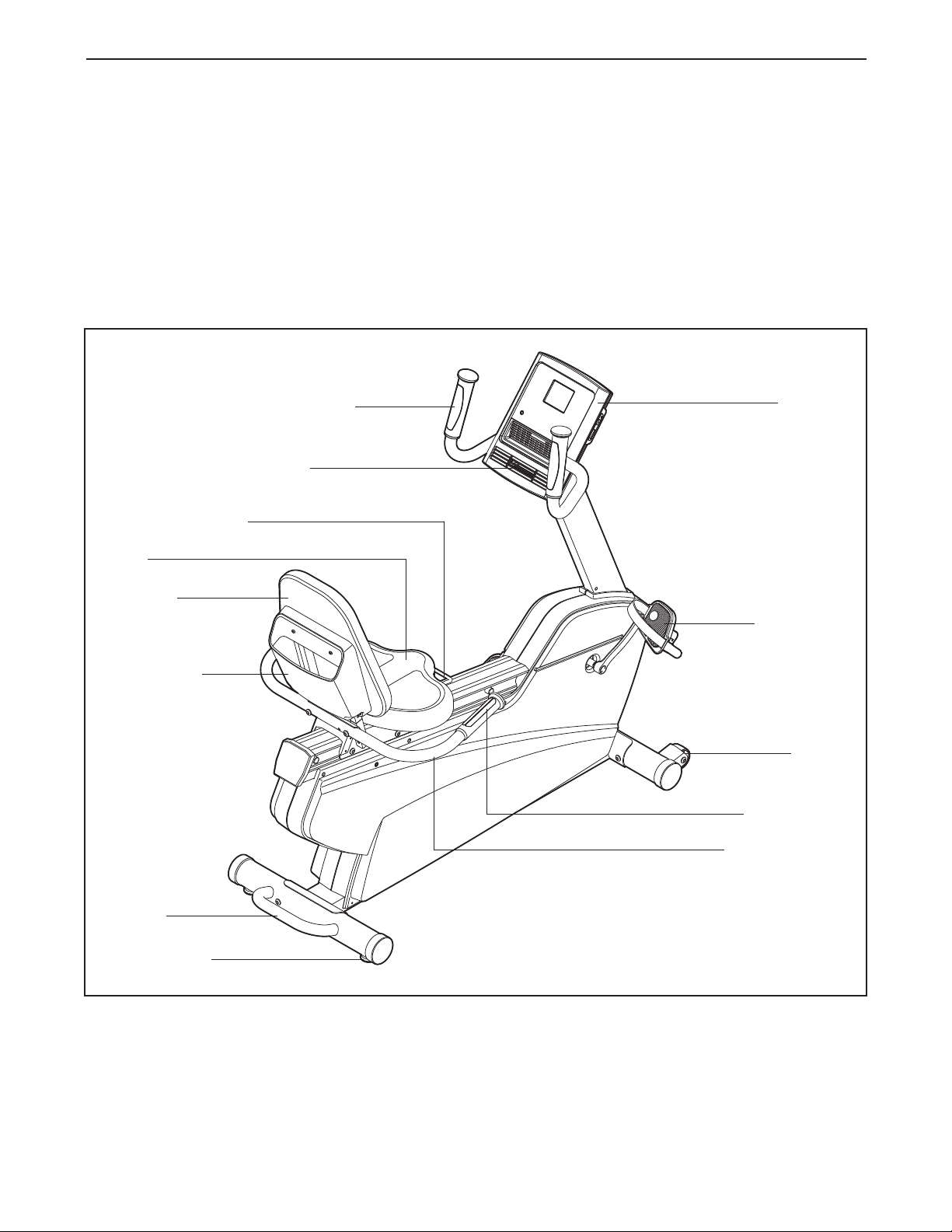
Handlebar
Fan
Adjustment Handle
Seat
®
fter reading this manual, please see the front cover
a
of this manual. To help us assist you, note the product
model number and serial number before contacting
us. The model number and the location of the serial
umber decal are shown on the front cover of this
n
manual.
Before reading further, please familiarize yourself with
the parts that are labeled in the drawing below.
Console
Backrest
Book Holder
Handle
Leveling Foot
Pedal/Strap
Wheel
Pulse Sensor
Seat Handlebar
4
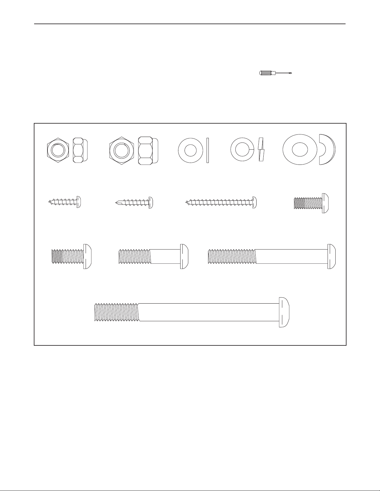
ASSEMBLY
M8 x 68mm Button
Bolt (70)–2
M8 x 35mm Button
Bolt (72)–2
M4 x 19mm Tek
Screw (75)–2
M4 x 38mm
Screw (89)–2
M10 Locknut
(91)–4
M8 Locknut
(99)–4
M8 Split
Washer (93)–10
M6 Washer
(88)–4
M8 Curved
Washer (86)–2
M4 x 16mm
Screw (77)–4
M10 x 96mm Button Bolt (65)–4
M6 x 16mm Patch
Screw (71)–4
M8 x 18mm Patch
Screw (67)–8
Assembly requires two persons. Place all parts of the exercise bike in a cleared area and remove the packing
materials. Do not dispose of the packing materials until assembly is completed.
In addition to the included tool(s), assembly requires a Phillips screwdriver .
See the drawings below to identify the small parts needed for assembly. The number in parentheses below each
drawing is the key number of the part, from the PART LIST near the end of this manual. The number following
the key number is the quantity needed for assembly. Note: If a part is not in the hardware kit, check to see if
it has been preassembled. To avoid damaging parts, do not use power tools for assembly.
5
1.
To make assembly easier, read the
nformation on page 5 before you begin.
i
Orient the Front Stabilizer (15) so that the
Wheels (17) are in the position shown.
1
17
5
6
Attach the Front Stabilizer (15) to the Frame (1)
with two M10 x 96mm Button Bolts (65) and two
M10 Locknuts (91). Note: Only one Locknut is
shown.
2. While another person lifts the rear of the Frame
(1), attach the Rear Stabilizer (16) to the Frame
with two M10 x 96mm Button Bolts (65) and two
M10 Locknuts (91).
17
15
1
91
2
91
91
1
65
16
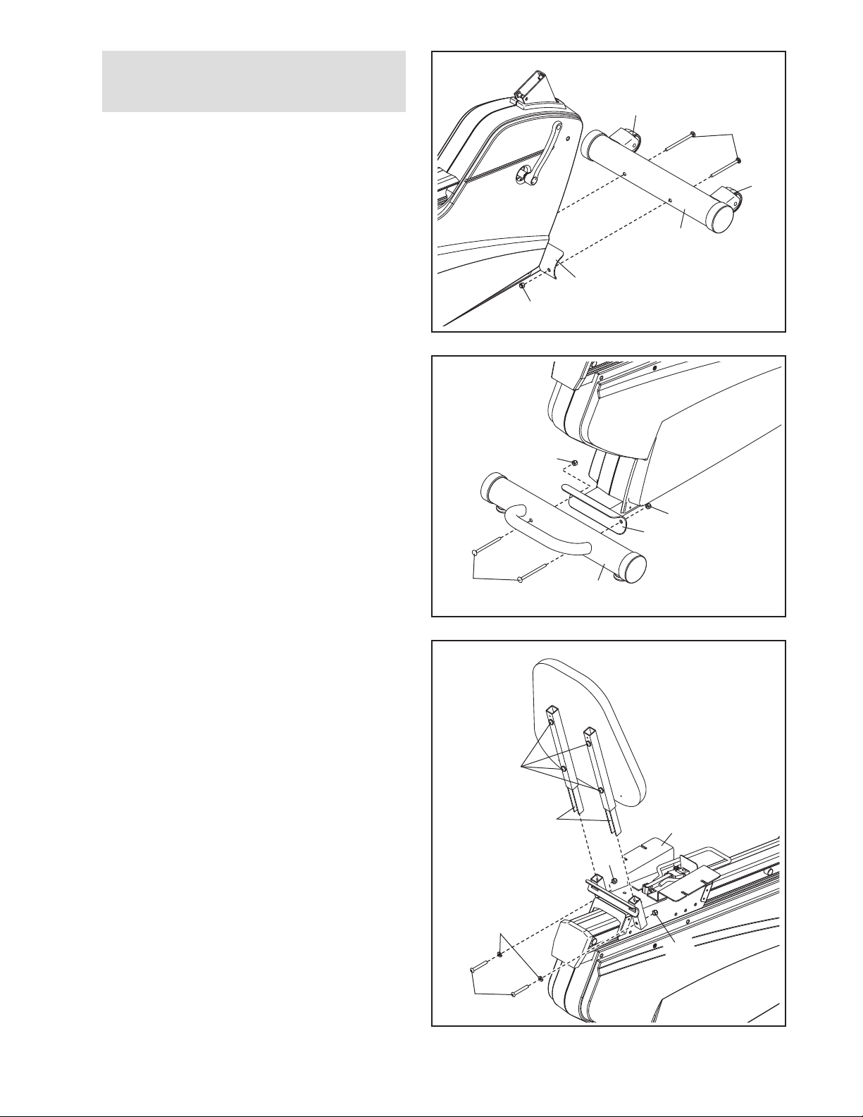
3. Tip: If the Backrest Tubes (52) do not slide
into the Seat Carriage (41), loosen the four
M6 x 38mm Button Screws (25).
Insert the Backrest Tubes (52) into the Seat
Carriage (41).
Attach each Backrest Tube (52) with an M8 x
35mm Button Bolt (72), an M8 Split Washer
(93), and an M8 Locknut (99). Make sure that
the Locknuts are in the hexagonal holes in
the Seat Carriage. Do not tighten the Button
Bolts yet.
3
25
52
99
93
72
41
99
6
4. Tip: Do not damage the wires inside the Seat
Handlebar (11) during this step.
ttach the Seat Handlebar (11) to the Seat
A
Carriage (41) with two M8 x 68mm Button Bolts
70), two M8 Curved Washers (86), and two M8
(
Locknuts (99). Make sure that the Locknuts
are in the hexagonal holes in the Seat
Carriage.
Then, plug the Lower Pulse Wire (58) into the
receptacle in the Right Shield (14).
See step 3. Tighten the two M8 x 35mm
Button Bolts (72).
4
11
86
1
4
99
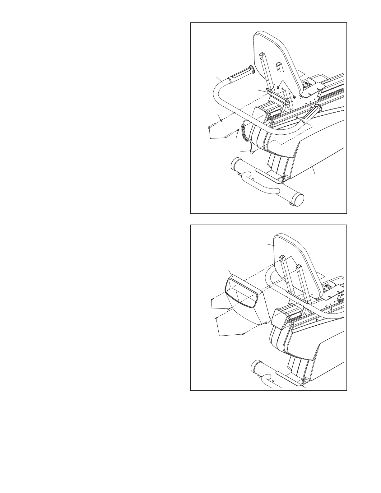
5. Attach the Book Holder (3) to the Backrest
Tubes (52) with two M4 x 19mm Tek Screws
(75).
Then, attach the Book Holder (3) to the
Backrest (8) with two M4 x 38mm Screws (89).
70
5
75
86
58
14
8
52
3
89
7
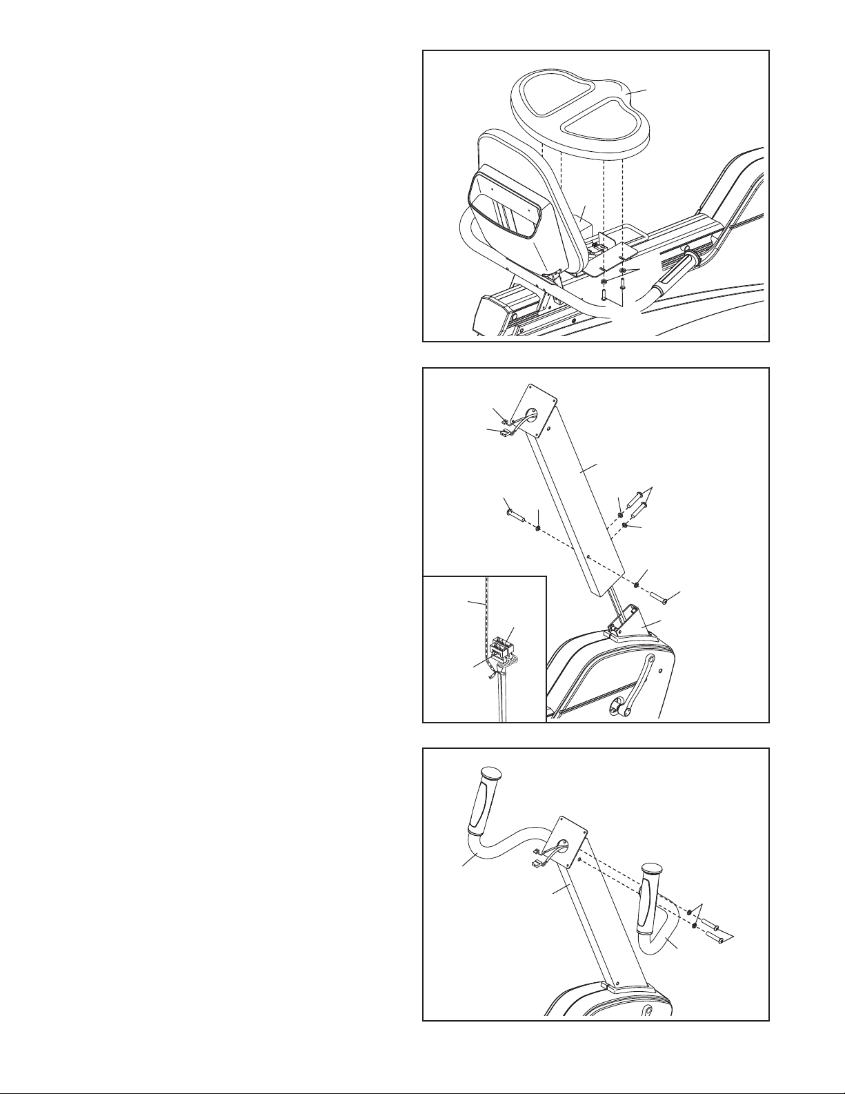
6. Attach the Seat (9) to the Seat Carriage (41)
with four M6 x 16mm Patch Screws (71) and
four M6 Washers (88). Note: Only two Patch
crews and two Washers are shown.
S
6
9
41
88
71
7. Have another person hold the Upright (2) near
the Frame (1).
See the inset drawing. Locate the wire tie in
the Upright (2). Tie the lower end of the wire tie
to the Main Wire Harness (43) and to the Upper
Pulse Wire (42). Next, pull the upper end of the
wire tie upward out of the top of the Upright.
Then, untie and discard the wire tie. Tip: Do
not allow the ends of the wires to fall into
the Upright. Use a piece of tape or an elastic
band to hold the wires in place until step 9.
Tip: Avoid pinching the wires. Attach the
Upright (2) to the Frame (1) with four M8 x
18mm Patch Screws (67) and four M8 Split
Washers (93). Tip: Tighten the two Patch
Screws in the front of the Upright and then
tighten the other two Patch Screws.
8. Identify the Right Handlebar (20), which is
marked with a “Right” sticker, and orient it as
shown.
7
Wire
Tie
8
42
43
42
67
43
93
Avoid pinching
the wires
2
67
93
93
93
67
1
Attach the Right Handlebar (20) to the Upright
(2) with two M8 x 18mm Patch Screws (67) and
two M8 Split Washers (93).
Attach the Left Handlebar (7) in the same
way.
7
2
93
67
20
8
 Loading...