

Reebok RBCCEL79021 User Manual
Model No. RBCCEL79021
www.weslo.com
Visit our website at
www.jumpking.com
Visit our website at
www.imagefitness.com
Visit our website at
www.reebokfitness.com
Visit our website at
Serial No.
Serial Number
Decal (on top
of the frame)
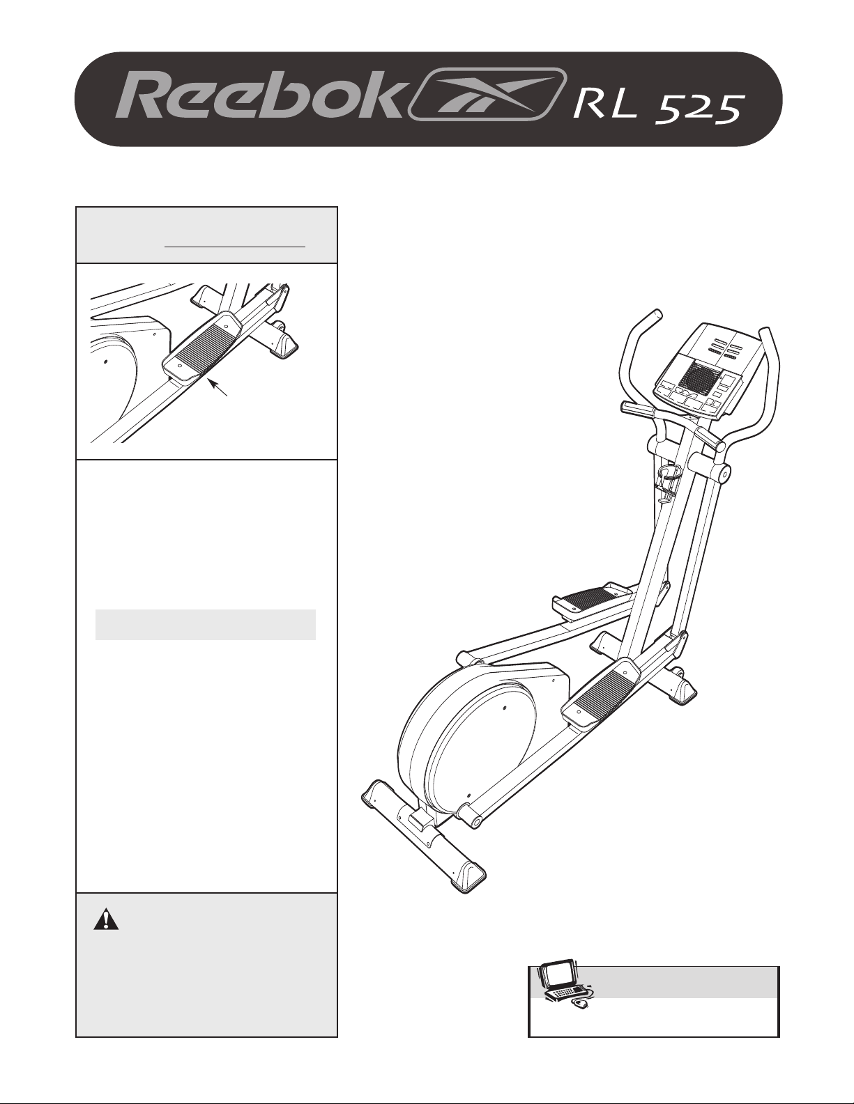
QUESTIONS?
As a manufacturer, we are committed to providing complete
customer satisfaction. If you
have questions, or if there are
missing parts, please call:
USER'S MANUAL
1-888-936-4266
Monday through Friday from
8h00 to 18h30 EST (excluding
holidays).
CAUTION
Read all precautions and instructions in this manual before using
this equipment. Keep this manual
for future reference.
Patent Pending

TABLE OF CONTENTS
MPORTANT PRECAUTIONS . . . . . . . . . . . . . . . . . . . . . . . . . . . . . . . . . . . . . . . . . . . . . . . . . . . . . . . . . . . . . . . .3
I
BEFORE YOU BEGIN . . . . . . . . . . . . . . . . . . . . . . . . . . . . . . . . . . . . . . . . . . . . . . . . . . . . . . . . . . . . . . . . . . . . . .4
SSEMBLY . . . . . . . . . . . . . . . . . . . . . . . . . . . . . . . . . . . . . . . . . . . . . . . . . . . . . . . . . . . . . . . . . . . . . . . . . . . . . . .5
A
ELLIPTICAL EXERCISER OPERATION . . . . . . . . . . . . . . . . . . . . . . . . . . . . . . . . . . . . . . . . . . . . . . . . . . . . . . .10
MAINTENANCE AND TROUBLESHOOTING . . . . . . . . . . . . . . . . . . . . . . . . . . . . . . . . . . . . . . . . . . . . . . . . . . .22
EXERCISE GUIDELINES . . . . . . . . . . . . . . . . . . . . . . . . . . . . . . . . . . . . . . . . . . . . . . . . . . . . . . . . . . . . . . . . . . .23
PART LIST . . . . . . . . . . . . . . . . . . . . . . . . . . . . . . . . . . . . . . . . . . . . . . . . . . . . . . . . . . . . . . . . . . . . . . . . . . . . . .25
EXPLODED DRAWING . . . . . . . . . . . . . . . . . . . . . . . . . . . . . . . . . . . . . . . . . . . . . . . . . . . . . . . . . . . . . . . . . . . .26
ORDERING REPLACEMENT PARTS . . . . . . . . . . . . . . . . . . . . . . . . . . . . . . . . . . . . . . . . . . . . . . . . . .Back Cover
LIMITED WARRANTY . . . . . . . . . . . . . . . . . . . . . . . . . . . . . . . . . . . . . . . . . . . . . . . . . . . . . . . . . . . . . .Back Cover
REEBOK and the Vector Logo are registered trademarks and service marks of Reebok. This product is
manufactured and distributed under license from Reebok International.
2
IMPORTANT PRECAUTIONS
0
A
209489
ADD PART NO. 210125 AND TABLE
1274-10
210125
REVISIONS
DRAWINGS PREVIOUS TO LAST REV. DATE ARE OBSOLETE
D
REV ECN DESCRIPTION OF CHANGE
WARNING:To reduce the risk of serious injury, read the following important precau-
tions before using the elliptical exerciser.
1. Read all instructions in this manual before
using the elliptical exerciser.
2. It is the responsibility of the owner to ensure
that all users of the elliptical exerciser are
adequately informed of all precautions.
3. The elliptical exerciser is intended for
in-home use only. Do not use the elliptical
exerciser in a commercial, rental, or institutional setting.
4. Place the elliptical exerciser on a level surface, with a mat beneath it to protect the
floor or carpet. Keep the elliptical exerciser
indoors, away from moisture and dust.
5. Inspect and properly tighten all parts regularly. Replace any worn parts immediately.
6. Keep children under age 12 and pets away
from the elliptical exerciser at all times.
7. The elliptical exerciser should not be used
by persons weighing more than 250 pounds.
8. Wear appropriate exercise clothing when
using the elliptical exerciser. Always wear
athletic shoes for foot protection.
9. Always hold the handlebar when mounting
dismounting the elliptical exerciser.
or
Always hold the handlebar or the upper body
arms when using the elliptical exerciser.
10. Keep your back straight when using the elliptical exerciser; do not arch your back.
11. If you feel pain or dizziness while exercis-
ing, stop immediately and begin cooling
down.
12. The pulse sensor is not a medical device.
Various factors, including the user's movement, may affect the accuracy of heart rate
readings. The pulse sensor is intended only
as an exercise aid in determining heart rate
trends in general.
13. When you stop exercising, allow the pedals
to slowly come to a stop. The elliptical exerciser does not have a free wheel; the pedals
will continue to move until the flywheel
stops.
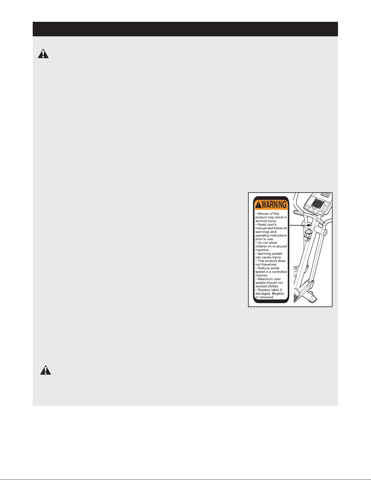
14. The decal
shown at the
right has
been placed
on the elliptical exerciser
in the indicated location. If the
decal is
missing or
illegible,
please call
our
Customer
Service
Department
toll-free at 1-888-936-4266, Monday through
Friday, 8h00 until 18h30 Eastern Time
(excluding holidays), to order a free replacement decal. Apply the replacement decal in
the location
shown.
WARNING:Before beginning this or any exercise program, consult your physician.
This is especially important for persons over the age of 35 or persons with pre-existing health problems. Read all instructions before using. ICON assumes no responsibility for personal injury or
property damage sustained by or through the use of this product.
3
BEFORE YOU BEGIN
ongratulations for selecting the new REEBOK
C
525 elliptical exerciser. The RL 525 elliptical exerciser
s an incredibly smooth exerciser that moves your feet
i
in a natural elliptical path, minimizing the impact on
your knees and ankles. And the unique RL 525 features adjustable resistance and a state-of-the-art console to help you get the most from your exercise.
Welcome to a whole new world of natural, ellipticalmotion exercise from REEBOK.
For your benefit, read this manual carefully before
you use the elliptical exerciser.
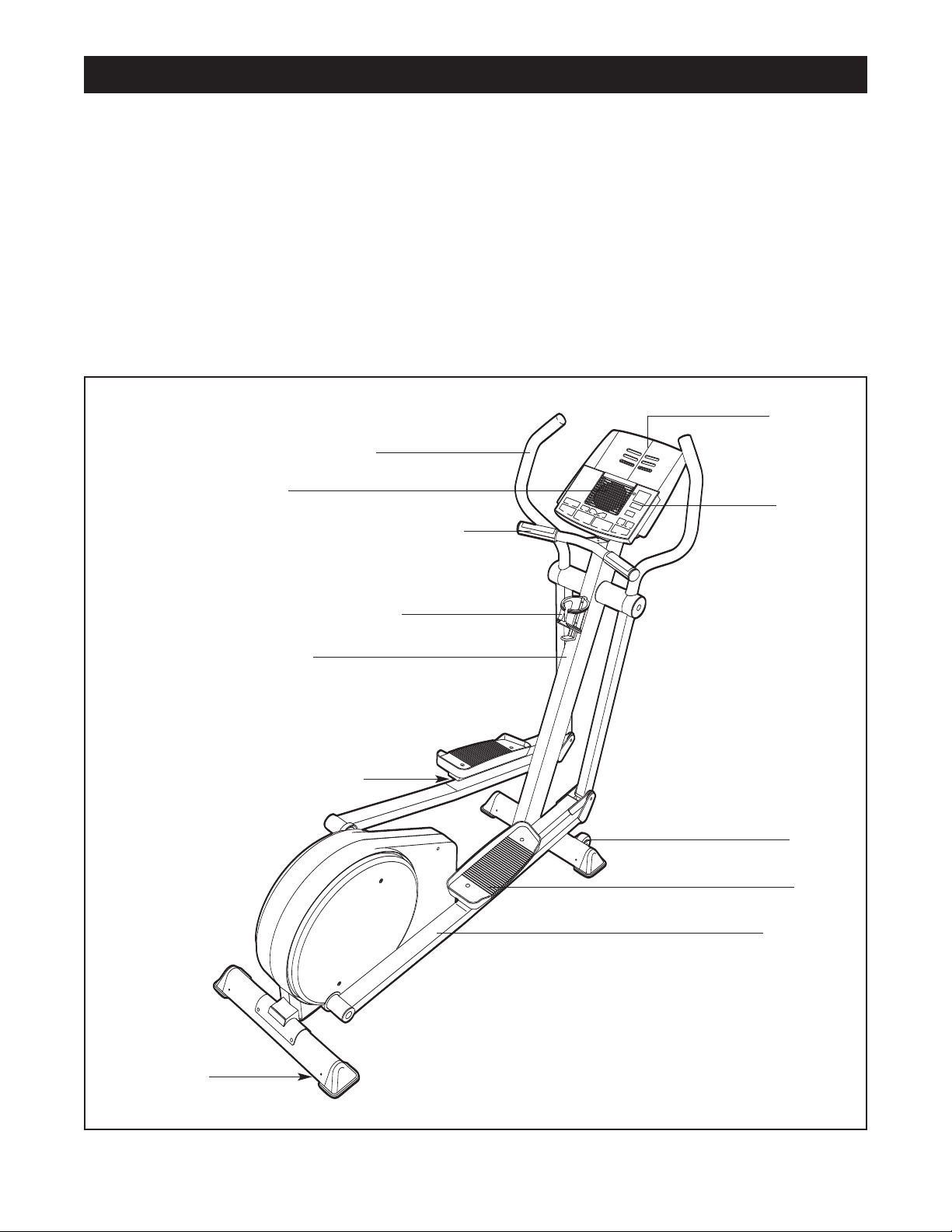
Upper Body Arm
Fan
Handlebar with Pulse Sensor
If you have addi-
®
L
R
ional questions, please call our Customer Service
t
Department at
riday, 8h00 until 18h30 Eastern Time (excluding holi-
F
days). To help us assist you, please mention the product model number and serial number when calling.
The model number is RBCCEL79021. The serial number can be found on a decal attached to the elliptical
exerciser (see the front cover of this manual for the
location of the decal).
Before reading further, please familiarize yourself with
the parts that are labeled in the drawing below.
1-888-936-4266, Monday through
Bookrack
Console
BACK
Water Bottle Holder*
Upright
Pedal Cushion
FRONT
Wheel
Pedal
Pedal Leg
RIGHT SIDE
Leveling Foot
*No water bottle is included
4
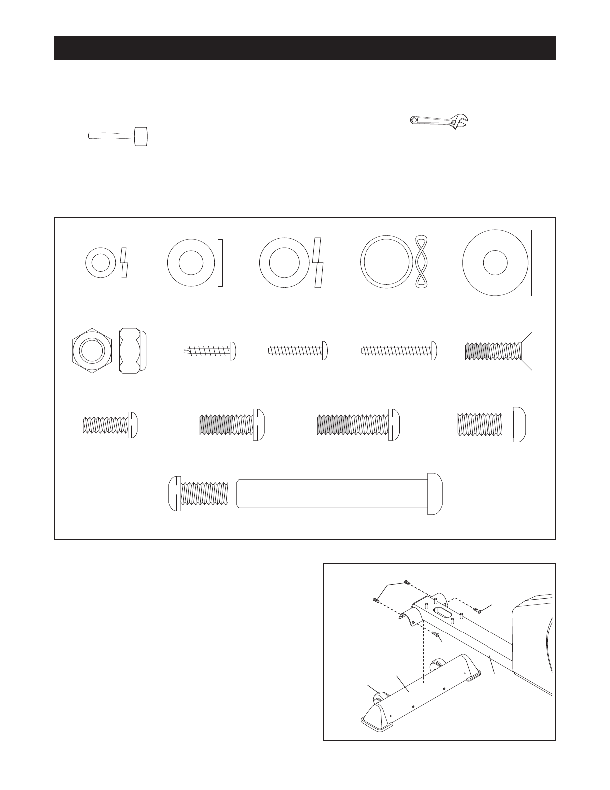
ASSEMBLY
M6 x 20mm Patch
Screw (75)–4
Large M8
Washer (70)–2
Small M8
Washer (71)–2
M4 x 25mm
Screw (96)–2
M4 x 16mm
Screw (82)—6
M4 x 19mm
Screw (92)–2
M6 Split Washer
(72)–2
M6 x 16mm Button
Screw (93)–2
Bolt Set (67)–2
M10 Nylon
Locknut (85)–4
M8 x 19mm Patch
Screw (81)–4
M8 x 25mm Patch
Screw (73)–10
M8 x 19mm Shoulder
Screw (102)–2
M10 Split
Washer (103)–4
Wave Washer
(101)–2
lace all parts of the elliptical exerciser in a cleared area and remove the packing materials. Do not dispose of
P
the packing materials until assembly is completed.
In addition to the included tools, assembly requires an adjustable wrench and a rubber
mallet .
Use the part drawings below to identify the small parts used in assembly. The number in parenthesis below
each drawing refers to the key number of the part, from the PART LIST on page 25. The second number refers
to the quantity used in assembly. Note: Some small parts may have been pre-assembled for shipping. If a
part is not in the parts bag, check to see if it has been pre-assembled.
1. Identify the Front Stabilizer (63), which has Wheels
(27) attached to one side. Attach the Front Stabilizer
to the front of the Frame (1) with four M8 x 25mm
Patch Screws (73).
1
5
27
73
73
73
63
1
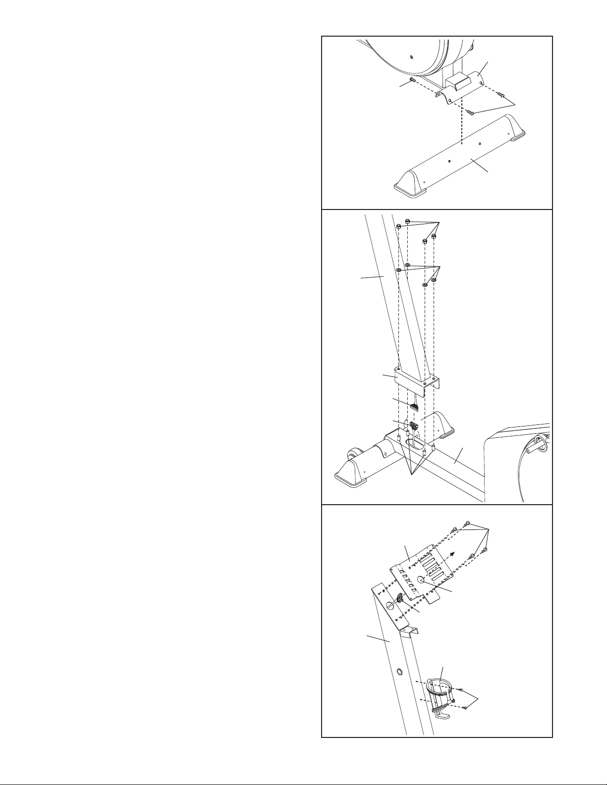
2. Attach the Rear Stabilizer (24) to the rear of the
rame (1) with four M8 x 25mm Patch Screws (73).
F
2
1
73
73
24
3. Remove the four M10 Nylon Locknuts (85) and the
four M10 Split Washers (103) from the welded bolts
near the front of the Frame (1).
While a second person holds the Upright (2), connect the Upper Wire Harness (15) to the Lower Wire
Harness (39).
Align the holes in the bracket on the lower end of the
Upright (2) with the welded bolts on the Frame (1).
Lower the Upright,
Harness (15) and the Lower Wire Harness (39) up
into the Upright, until the welded bolts are fully
inserted into the bracket. Be careful to avoid
pinching and damaging the Wire Harnesses.
Tighten the four M10 Nylon Locknuts (85) and the
four M10 Split Washers (103) onto the welded bolts
on the Frame (1).
feeding the Upper Wire
3
85
103
2
Be careful to
avoid pinching
and damaging the
Wire Harnesses
(15, 39) during
this step.
Bracket
15
39
1
Welded
Bolts
4. Feed the Upper Wire Harness (15) up through the
indicated hole in the Console Bracket (3).
Console Bracket to the Upright (2) with four M8 x
19mm Patch Screws (81).
pinching and damaging the Upper Wire Harness.
Attach the Water Bottle Holder (13) to the Upright (2)
with two M4 x 19mm Screws (92). Note: The water
bottle holder is designed to be used with your own
water bottle.
Be careful to avoid
Attach the
4
81
3
Hole
15
2
13
92
6
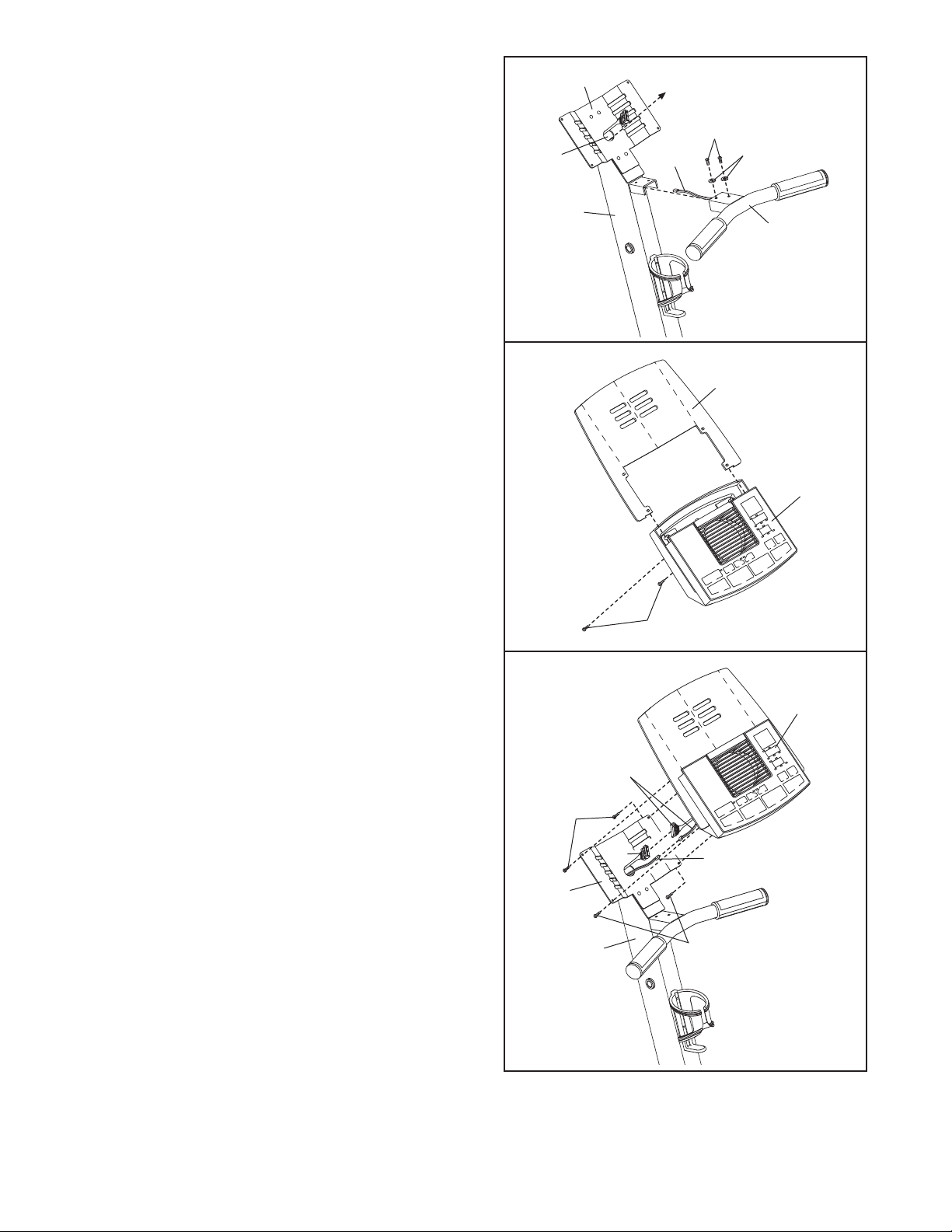
5. While another person holds the Handlebar (4) near
the Upright (2), feed the Pulse Sensor Wire (14) into
he Upright and out of the indicated hole in the
t
Console Bracket (3). Attach the Handlebar to the
pright with two M6 x 16mm Button Screws (93)
U
and two M6 Split Washers (72). Be careful to
avoid pinching and damaging the Pulse Sensor
Wire.
5
Hole
3
93
4
1
2
72
4
6. Insert the Bookrack (7) into the slots in the Console
(8). Attach the Bookrack to the Console with two M4
x 25mm Screws (96). Be careful to avoid pinching
and damaging the wires in the Console.
7. While another person holds the Console (8) near
the Console Bracket (3), connect the Pulse Sensor
Wire (14) and the Upper Wire Harness (15) to the
corresponding wires on the Console.
Insert all excess wiring down into the Upright
(2). Attach the Console (8) to the Console Bracket
(3) with four M4 x 16mm Screws (82). Be careful to
avoid pinching and damaging the Pulse Sensor
Wire (14) and the Upper Wire Harness (15).
6
7
8
96
7
8
Console
Wires
82
15
3
2
14
82
7
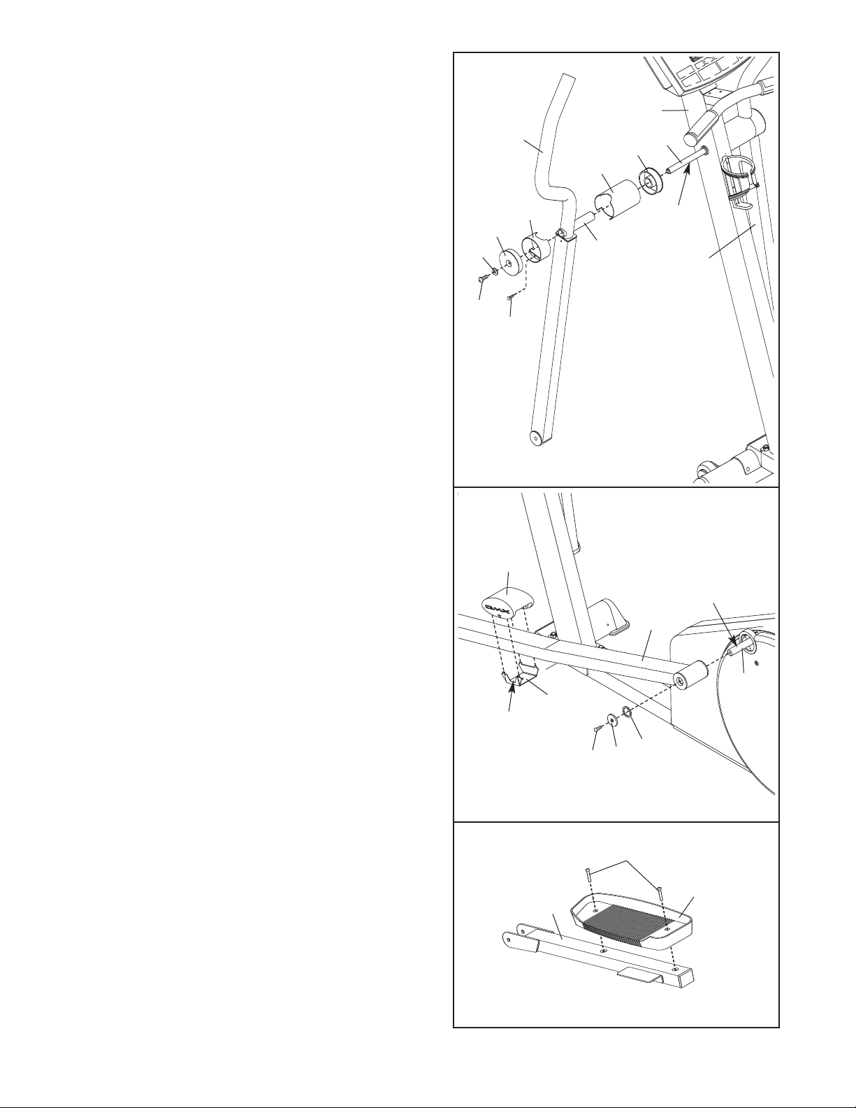
8. Insert the Pivot Axle (21) into the Upright (2), and
center the Pivot Axle. Apply a small amount of the
ncluded grease to both ends of the Pivot Axle.
i
dentify the Left Upper Body Arm (5), which is
I
marked with a decal. Insert an Upright Bushing (20)
into an Upright Spacer (19). Turn the Upright
Spacer so that the semicircular cutout is at the top,
and slide the Upright Spacer onto the post on the
Left Upper Body Arm.
Slide the Left Upper Body Arm (5) onto the Pivot
Axle (21). Attach a Pivot Spacer (17) to the Left
Upper Body Arm with an M4 x 16mm Screw (82).
Turn a Pivot Endcap (16) so that the rectangular
cutout is at the bottom. Using a rubber mallet, tap
the Pivot Endcap into the Pivot Spacer.
Slide a Small M8 Washer (71) onto an M8 x 19mm
Shoulder Screw (102), and tighten the Patch Screw
into the Pivot Axle (21).
Attach the Right Upper Body Arm (6) in the
same way.
8
102
71
16
82
2
5
9
1
17
Post
20
21
Grease
6
9. Apply a small amount of grease to the axle on the
left Crank Arm (40). Identify the Left Pedal Leg (28),
which is marked with a decal. Slide the Left Pedal
Leg onto the axle on the left Crank Arm (40). Slide a
Large M8 Washer (70) and a Wave Washer (101)
onto an M8 x 25mm Patch Screw (73), and tighten
the Patch Screw into the axle.
Wave Washer is on the axle before tightening the
Patch Screw.
Snap a Pedal Cushion (74) around the Left Pedal
Leg (28) onto a Cushion Bracket (99). Make sure that
the arrow on the Pedal Cushion is pointing to one of
the numbers on the Left Pedal Leg and that the num
ber shows through the window in the Cushion
Bracket.
Assemble the Right Pedal Leg (not shown) in the
same way.
Identify the Left Pedal Arm (33), which is marked
10.
with a decal. Attach the Left Pedal (35) to the Left
Pedal Arm with two M6 x 20mm Patch Screws (75)
as shown.
Attach the Right Pedal (not shown) to the Right
Pedal Arm (not shown) in the same way.
Make sure that the
9
74
Grease
28
40
33
99
73
70
101
75
35
Window
10
8
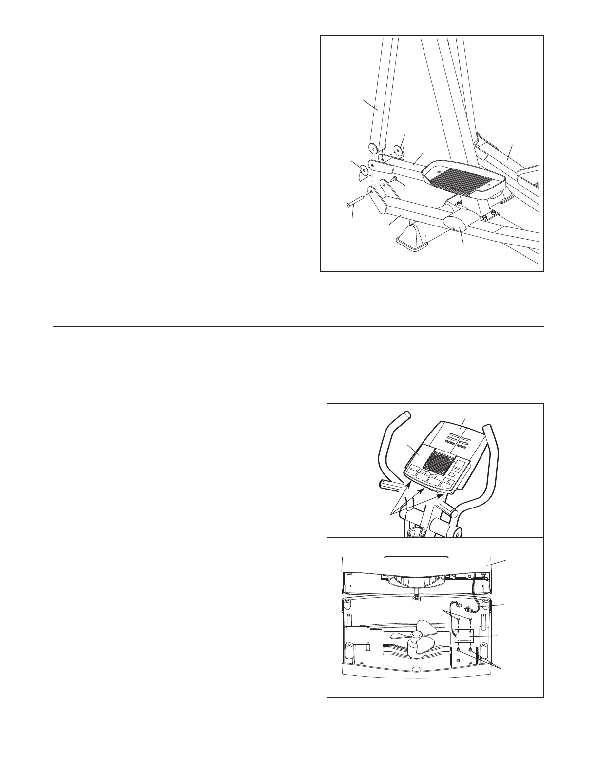
11. Set the Left Pedal Arm (33) on the left Pedal Cushion
(74), and hold the end of the Left Pedal Arm inside of
he bracket on the Left Pedal Leg (28).
t
old a Plastic Pedal Arm Spacer (65) between the
H
Left Pedal Leg (28) and the Left Pedal Arm (33).
Insert the long part of a Bolt Set (67) through the Left
Pedal Leg, the Plastic Pedal Arm Spacer, and the
Left Pedal Arm.
Lift the Left Pedal Leg (28), and hold the lower end of
the Left Upper Body Arm (5) inside of the bracket on
the Left Pedal Arm (33). Insert the long part of the
Bolt Set (67) through the Left Upper Body Arm. Hold
another Plastic Pedal Arm Spacer (65) between the
Left Pedal Arm and the Left Pedal Leg, and insert the
long part of the Bolt Set through these parts. Tighten
the short part of the Bolt Set into the long part.
Attach the Right Pedal Arm (32) in the same way.
12. Make sure that all parts are properly tightened before you use the elliptical exerciser. Note: Some
hardware may be left over after assembly is completed.
11
65
67
5
65
32
33
67
28
74
HOW TO INSTALL THE RECEIVER FOR THE OPTIONAL CHEST PULSE SENSOR
The elliptical exerciser is now fully assembled. If you purchase the optional chest pulse sensor (see
page 21), follow the steps below to install the receiver included with the chest pulse sensor.
1. See assembly step 6 on page 7, and remove the two
M4 x 25mm Screws (not shown) and the Bookrack (7).
Next, look under the Console (8) and locate the three
indicated screws (not shown). Remove the three
screws. Do not remove the screws attaching the
Console to the Console Bracket (not shown).
2. Carefully lift the top of the Console (8) as shown. Using
the two small screws included with the chest pulse sensor, attach the receiver to the indicated plastic posts on
the Console.
exactly as shown.
the indicated wire on the Console.
See step 1 above. Lower the top of the Console (8).
Make sure that no wires are pinched. Reattach the
top of the Console with the three screws removed in
step 1.
the Bookrack (7) with the two M4 x 25mm Screws (not
shown). N
chest pulse sensor may be discarded.
Make sure that the receiver is turned
Connect the wire on the receiver to
See assembly step 6 on page 7, and reattach
ote: The remaining wires included with the
1
2
Screws
8
Screws
7
8
Wire
Receiver
Posts
9
 Loading...