


Reebok RBCCEL779100 Owner's Manual
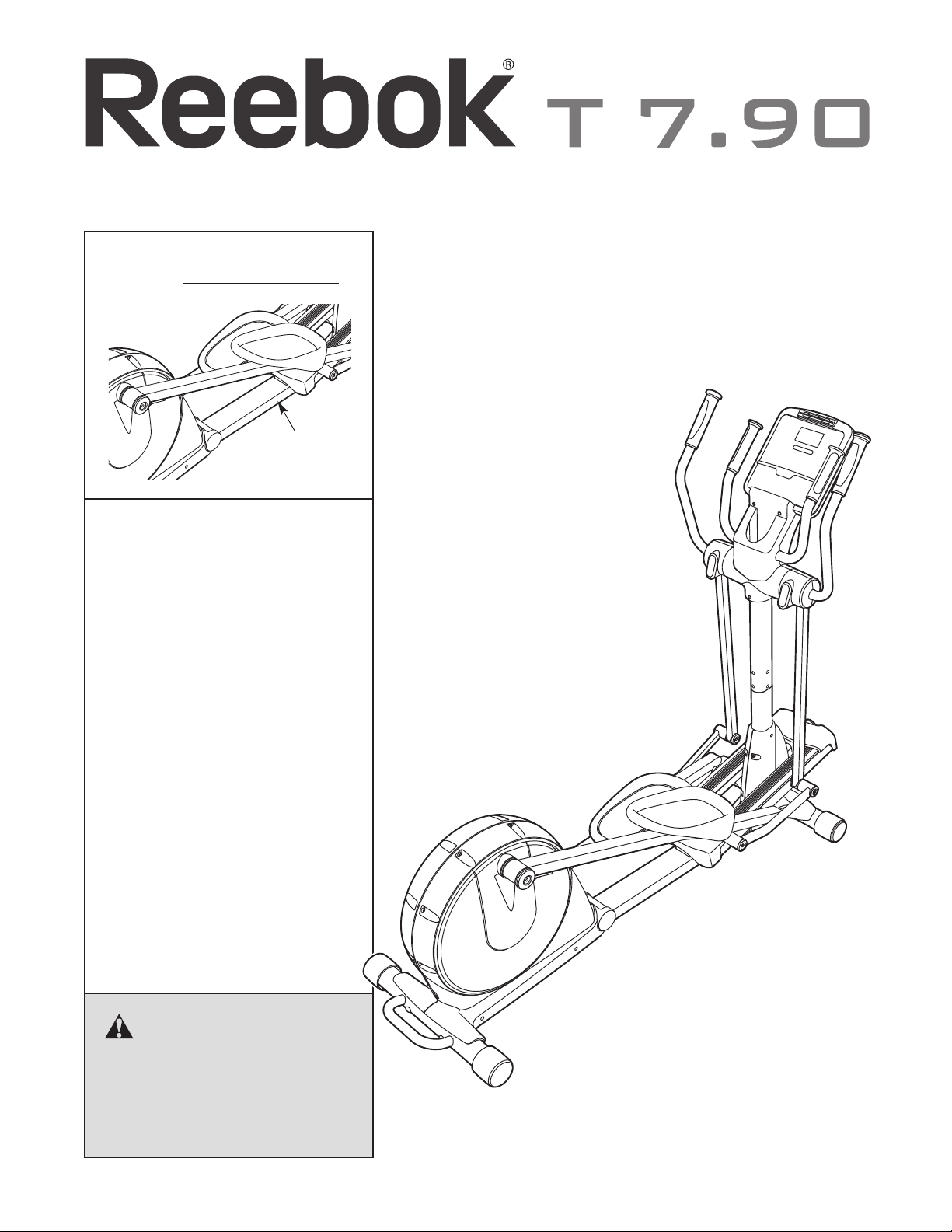
Model No. RBCCEL77910.0
Serial No.
Serial
Number
Decal
QUESTIONS?
If you have questions, or if parts
are damaged or missing, PLEASE
CONTACT OUR CUSTOMER
SERVICE DEPARTMENT
DIRECTLY.
CALL TOLL-FREE:
1-888-936-4266
Mon.–Fri., 7:30 until 16:30 ET
(excluding holidays)
USERʼS MANUAL
OR E-MAIL US:
customerservice@iconcanada.ca
CAUTION
Read all precautions and instructions in this manual before using
this equipment. Keep this manual
for future reference.
www.reebokfitness.com
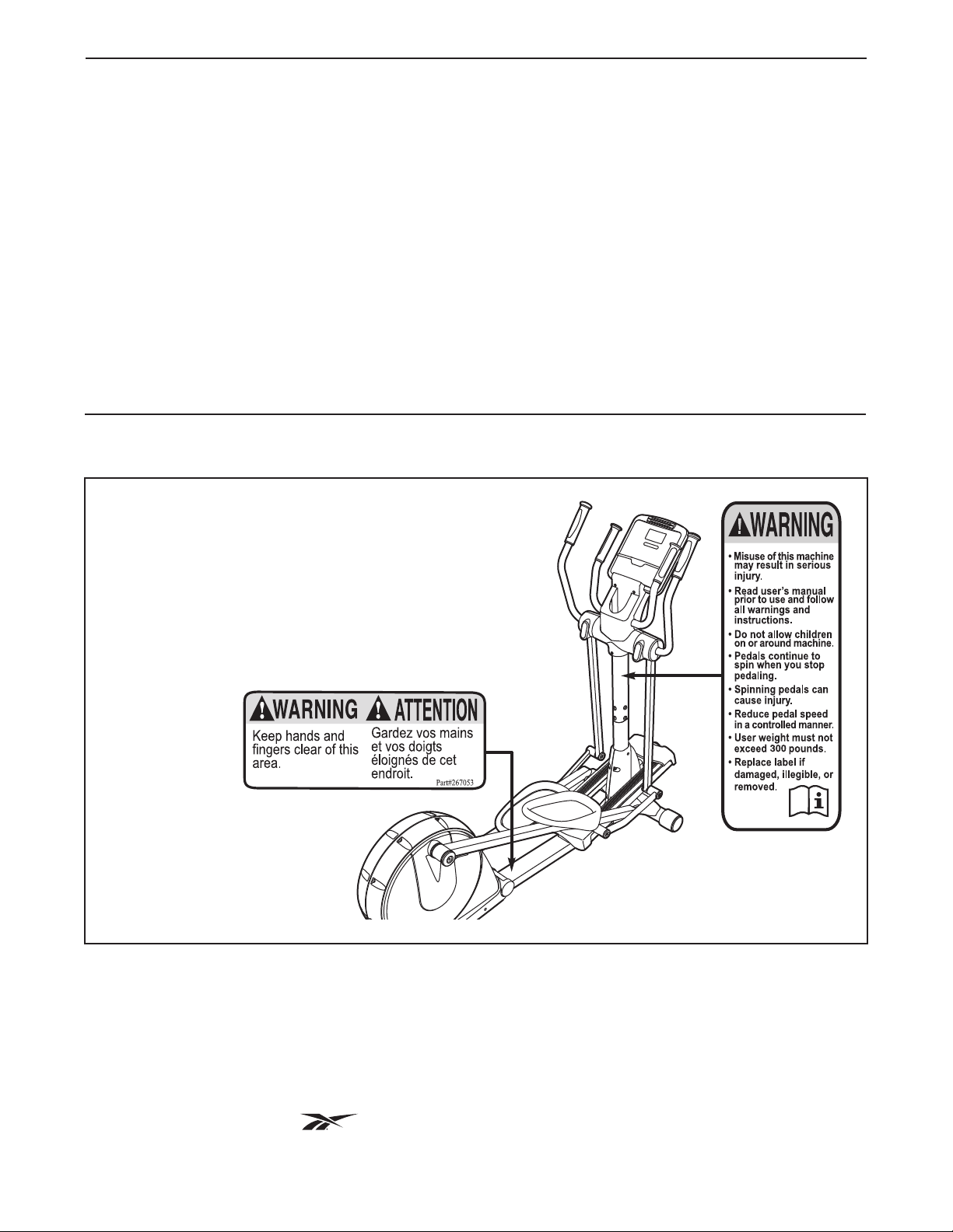
TABLE OF CONTENTS
WARNING DECAL PLACEMENT . . . . . . . . . . . . . . . . . . . . . . . . . . . . . . . . . . . . . . . . . . . . . . . . . . . . . . . . . . . . . .2
MPORTANT PRECAUTIONS . . . . . . . . . . . . . . . . . . . . . . . . . . . . . . . . . . . . . . . . . . . . . . . . . . . . . . . . . . . . . . . .3
I
BEFORE YOU BEGIN . . . . . . . . . . . . . . . . . . . . . . . . . . . . . . . . . . . . . . . . . . . . . . . . . . . . . . . . . . . . . . . . . . . . . .4
ASSEMBLY . . . . . . . . . . . . . . . . . . . . . . . . . . . . . . . . . . . . . . . . . . . . . . . . . . . . . . . . . . . . . . . . . . . . . . . . . . . . . . .5
HOW TO USE THE ELLIPTICAL . . . . . . . . . . . . . . . . . . . . . . . . . . . . . . . . . . . . . . . . . . . . . . . . . . . . . . . . . . . . .12
MAINTENANCE AND TROUBLESHOOTING . . . . . . . . . . . . . . . . . . . . . . . . . . . . . . . . . . . . . . . . . . . . . . . . . . .20
EXERCISE GUIDELINES . . . . . . . . . . . . . . . . . . . . . . . . . . . . . . . . . . . . . . . . . . . . . . . . . . . . . . . . . . . . . . . . . . .21
PART LIST . . . . . . . . . . . . . . . . . . . . . . . . . . . . . . . . . . . . . . . . . . . . . . . . . . . . . . . . . . . . . . . . . . . . . . . . . . . . . .24
EXPLODED DRAWING . . . . . . . . . . . . . . . . . . . . . . . . . . . . . . . . . . . . . . . . . . . . . . . . . . . . . . . . . . . . . . . . . . . .26
ORDERING REPLACEMENT PARTS . . . . . . . . . . . . . . . . . . . . . . . . . . . . . . . . . . . . . . . . . . . . . . . . . .Back Cover
LIMITED WARRANTY . . . . . . . . . . . . . . . . . . . . . . . . . . . . . . . . . . . . . . . . . . . . . . . . . . . . . . . . . . . . . .Back Cover
WARNING DECAL PLACEMENT
This drawing shows the location(s) of the warning
decal(s). If a decal is missing or illegible, see
the front cover of this manual and request a
free replacement decal. Apply the decal in the
location shown. Note: The decal(s) may not be
shown at actual size.
REEBOK and the Vector Logo are registered trademarks and service marks of Reebok. This product is
manufactured and distributed under license from Reebok International.
2

IMPORTANT PRECAUTIONS
WARNING: To reduce the risk of serious injury, read all important precautions and
instructions in this manual and all warnings on your elliptical before using your elliptical. ICON
ssumes no responsibility for personal injury or property damage sustained by or through the use of
a
this product.
1. Before beginning any exercise program,
consult your physician. This is especially
important for persons over age 35 or
persons with pre-existing health problems.
2. Use the elliptical only as described in this
manual.
3. It is the responsibility of the owner to ensure
that all users of the elliptical are adequately
informed of all precautions.
4. The elliptical is intended for home use only.
Do not use the elliptical in a commercial,
rental, or institutional setting.
5. Keep the elliptical indoors, away from
moisture and dust. Do not put the elliptical in
a garage or covered patio, or near water.
6. Place the elliptical on a level surface, with at
least 3 ft. (0.9 m) of clearance in the front
and rear of the elliptical and 2 ft. (0.6 m) on
each side. To protect the floor or carpet from
damage, place a mat under the elliptical.
9. The elliptical should not be used by persons
weighing more than 300 lbs. (136 kg).
10. Wear appropriate clothes while exercising;
do not wear loose clothes that could become
caught on the elliptical. Always wear athletic
shoes for foot protection while exercising.
11. Hold the handlebars or the upper body arms
when mounting, dismounting, or using the
elliptical.
12. The pulse sensor is not a medical device.
Various factors may affect the accuracy of
heart rate readings. The pulse sensor is
intended only as an exercise aid in
determining heart rate trends in general.
13. The elliptical does not have a freewheel; the
pedals will continue to move until the
flywheel stops. Reduce your pedaling speed
in a controlled way.
14. Keep your back straight while using the
elliptical; do not arch your back.
7. Inspect and properly tighten all parts
regularly. Replace any worn parts
immediately.
8. Keep children under age 12 and pets away
from the elliptical at all times.
15. Over exercising may result in serious injury
or death. If you feel faint or if you experience
pain while exercising, stop immediately and
cool down.
3
BEFORE YOU BEGIN
Thank you for selecting the revolutionary REEBOK®T
.90 elliptical. The T 7.90 elliptical provides an impres-
7
sive selection of features designed to make your workouts at home more effective and enjoyable.
For your benefit, read this manual carefully before
you use the elliptical. If you have questions after
reading this manual, please see the front cover of this
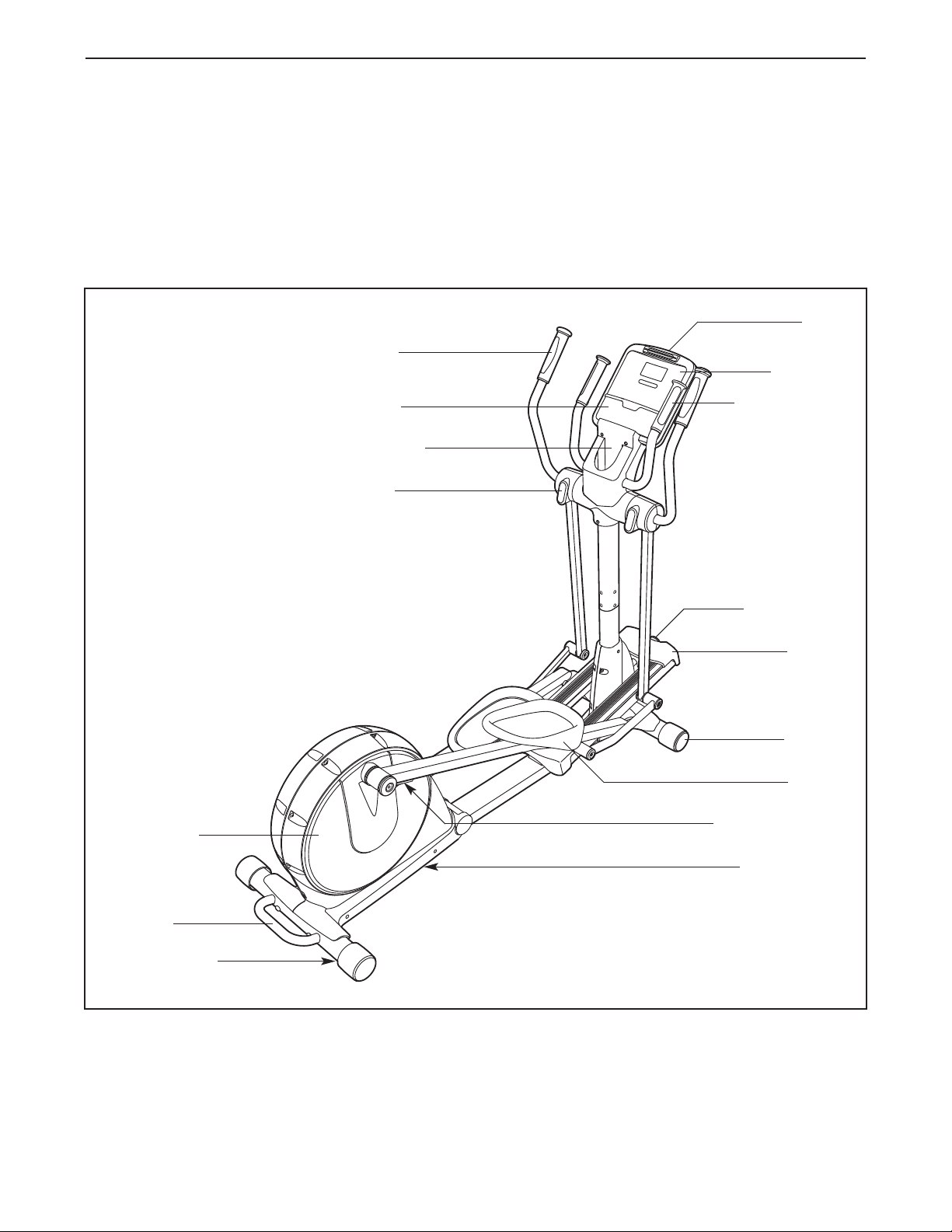
Upper Body Arm
Stereo Speakers
Water Bottle Holder*
Storage Magnet
manual. To help us assist you, note the product model
umber and serial number before contacting us. The
n
model number and the location of the serial number
decal are shown on the front cover of this manual.
Before reading further, please familiarize yourself with
the parts that are labeled in the drawing below.
Fan
Console
Pulse Sensor
Pedal Disc
Handle
Leveling Foot
Incline Knob
Ramp
Wheel
Pedal
Pedal Arm Latch
Latch Button
*Water bottle is not included
4
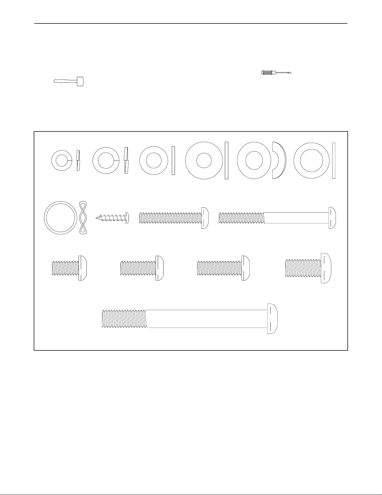
M10 x 93mm Button Screw (82)–4
M10 x 25mm
Washer (87)–2
M8 Split
Washer (101)–4
M4 x 16mm
Screw (97)–16
M6 Split Washer
(102)–8
M6 x 35mm
Screw (109)–4
M6 x 62mm
Screw (108)–4
M8.5 x 16mm x
1.5mm Washer
(103)–6
Link Arm
Spacer (74)–4
M8 x 20mm Button
Screw (107)–4
M8 x 25mm Button
Screw (110)–2
M10 x 20mm Button
Screw (111)–2
M8 x 15mm Button
Screw (106)–10
M10 Curved
Washer (99)–4
Wave Washer
(100)–2
ASSEMBLY
Assembly requires two persons. Place all parts of the elliptical in a cleared area and remove the packing
materials. Do not dispose of the packing materials until assembly is completed.
In addition to the included tool(s), assembly requires a Phillips screwdriver and a rubber
mallet .
See the drawings below to identify the small parts needed for assembly. The number in parentheses below each
drawing is the key number of the part, from the PART LIST near the end of this manual. The number following
the key number is the quantity needed for assembly. Note: If a part is not in the hardware kit, check to see if
it has been preassembled. To avoid damaging parts, do not use power tools for assembly.
5
1.
To make assembly easier, read the
nformation on page 5 before you begin.
i
See HOW TO FOLD AND UNFOLD THE
ELLIPTICAL on page 12 and unfold the
elliptical.
1
82
99
99
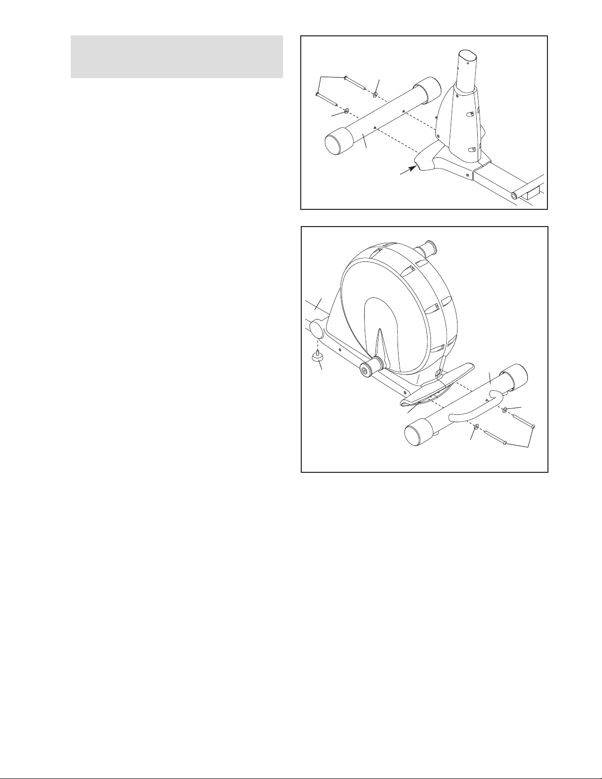
While another person lifts the front of the Frame
(1), attach the Front Stabilizer (4) to the Frame
with two M10 x 93mm Button Screws (82) and
two M10 Curved Washers (99).
2. While another person lifts the Folding Frame
(2), attach the Rear Stabilizer (3) to the Folding
Frame with two M10 x 93mm Button Screws
(82) and two M10 Curved Washers (99).
Next, tighten the Center Foot (95) into the
Frame (1).
4
1
2
1
95
2
3
99
99
82
6
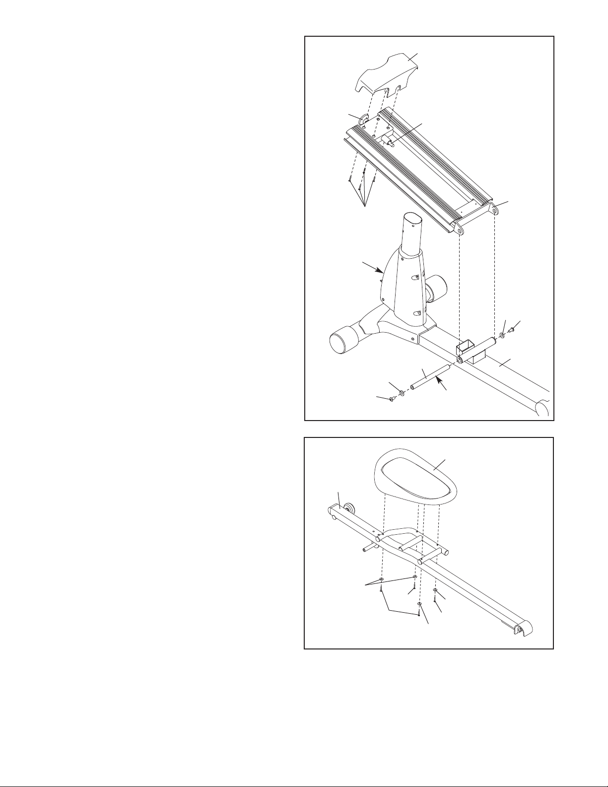
3. Attach the Front Ramp Cover (6) to the
amp (5) with four M4 x 16mm Screws (97).
R
Slide an M10 x 25mm Washer (87) onto an
M10 x 20mm Button Screw (111). Tighten the
Button Screw into one end of the Ramp
Axle (72). Apply a small amount of the included
rease to the Ramp Axle.
g
Orient the Ramp (5) as shown. Align the lower
end of the Ramp with the welded tube on the
Frame (1). Insert the Ramp Axle (72) into the
Ramp and the welded tube. Then, pull the
Ramp Knob (9), lower the Ramp, and engage
the Ramp Pin (62) in one of the three adjustment holes in the front of the Frame.
3
9
97
6
62
5
Slide an M10 x 25mm Washer (87) onto an
M10 x 20mm Button Screw (111). Tighten the
Button Screw into the open end of the Ramp
Axle (72).
4. Identify the Left Pedal (34) and the Left Pedal
Arm (32), which are marked with stickers.
Attach the Left Pedal (34) to the Left Pedal
Arm (32) with two M6 x 62mm Screws (108),
two M6 x 35mm Screws (109), and four M6
Split Washers (102).
Adjustment
Holes
4
32
111
87
72
Grease
34
87
111
1
Attach the Right Pedal (not shown) to the
Right Pedal Arm (not shown) in the same
way.
102
109
108
102
109
102
7
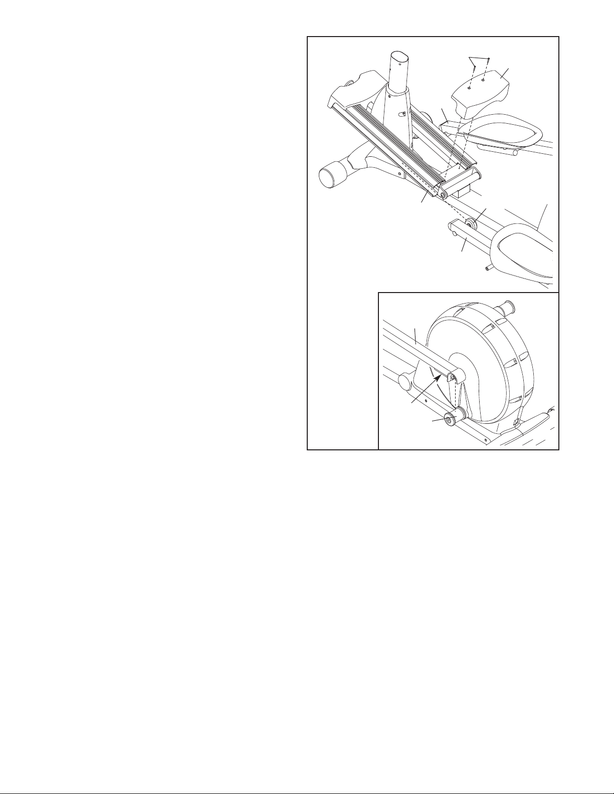
5. Insert the Roller (38) on the Left Pedal Arm (32)
and the Roller on the Right Pedal Arm (33) into
the sides of the Ramp (5).
Attach the Rear Ramp Cover (7) to the
amp (5) with two M4 x 16mm Screws (97).
R
See the inset drawing. Lift the Pedal Arm
atch (41) on the Left Pedal Arm (32), and set
L
the end of the Left Pedal Arm on the left Crank
Bushing Sleeve (54). Release the Pedal Arm
Latch, and make sure that the Left Pedal Arm is
securely connected to the Crank Bushing
Sleeve.
Connect the Right Pedal Arm (not shown) to
the right Crank Bushing Sleeve (not shown)
in the same way.
5
5
32
97
3
3
32
7
38
41
54
8
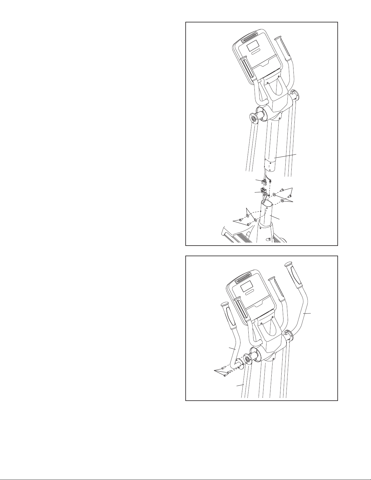
6. While another person holds the Upright (10)
near the Frame (1), connect the Upper Wire
Harness (65) to the Lower Wire Harness (64).
Tip: Avoid damaging the Wire Harnesses (64,
5). Carefully insert the Upright (10) into the
6
Frame (1). Attach the Upright with four M8 x
20mm Button Screws (107) and four M8 Split
Washers (101).
6
void damag-
A
ing the Wire
Harnesses
(64, 65)
101
10
65
107
64
101
7. Attach the Left Upper Body Arm (22) to the left
Upper Body Leg (24) with three M8 x 15mm
Button Screws (106).
Attach the Right Upper Body Arm (23) in the
same way.
107
7
22
106
24
1
23
9