

Page 1
Model No. RBBE2057.0
Visit our website at
www.weslo.com
new products, prizes,
fitness tips, and much more!
Visit our website at
www.imagefitness.com
new products, prizes,
fitness tips, and much more!
Visit our website at
www.workoutwarehouse.com
new products, prizes,
fitness tips, and much more!
Visit our website at
www.freemotionfitness.com
Visit our website at
www.reebokhomefitness.com
new products, prizes,
fitness tips, and much more!
Serial No.
Write the serial number in the
space above for future reference.
USER’S MANUAL
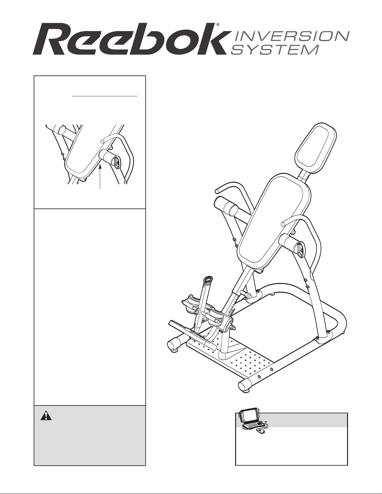
Serial Number Decal
(under backrest)
QUESTIONS?
As a manufacturer, we are committed to providing complete customer satisfaction. If you have
questions, or if parts are missing,
PLEASE DO NOT CONTACT
THE STORE; please contact
Customer Care.
IMPORTANT: You must note the
product model number and
serial number (see the drawing
above) before contacting us:
OLL-FREE:
T
CALL
1-877-994-4999
Mon.–Fri. 6 a.m.–6 p.m. MST
Sat. 8 a.m.–4 p.m. MST
ON THE WEB:
www.reebokservice.com
CAUTION
Read all precautions and instruc
tions in this manual before using
this equipment. Save this manual
for future reference.
-
Page 2
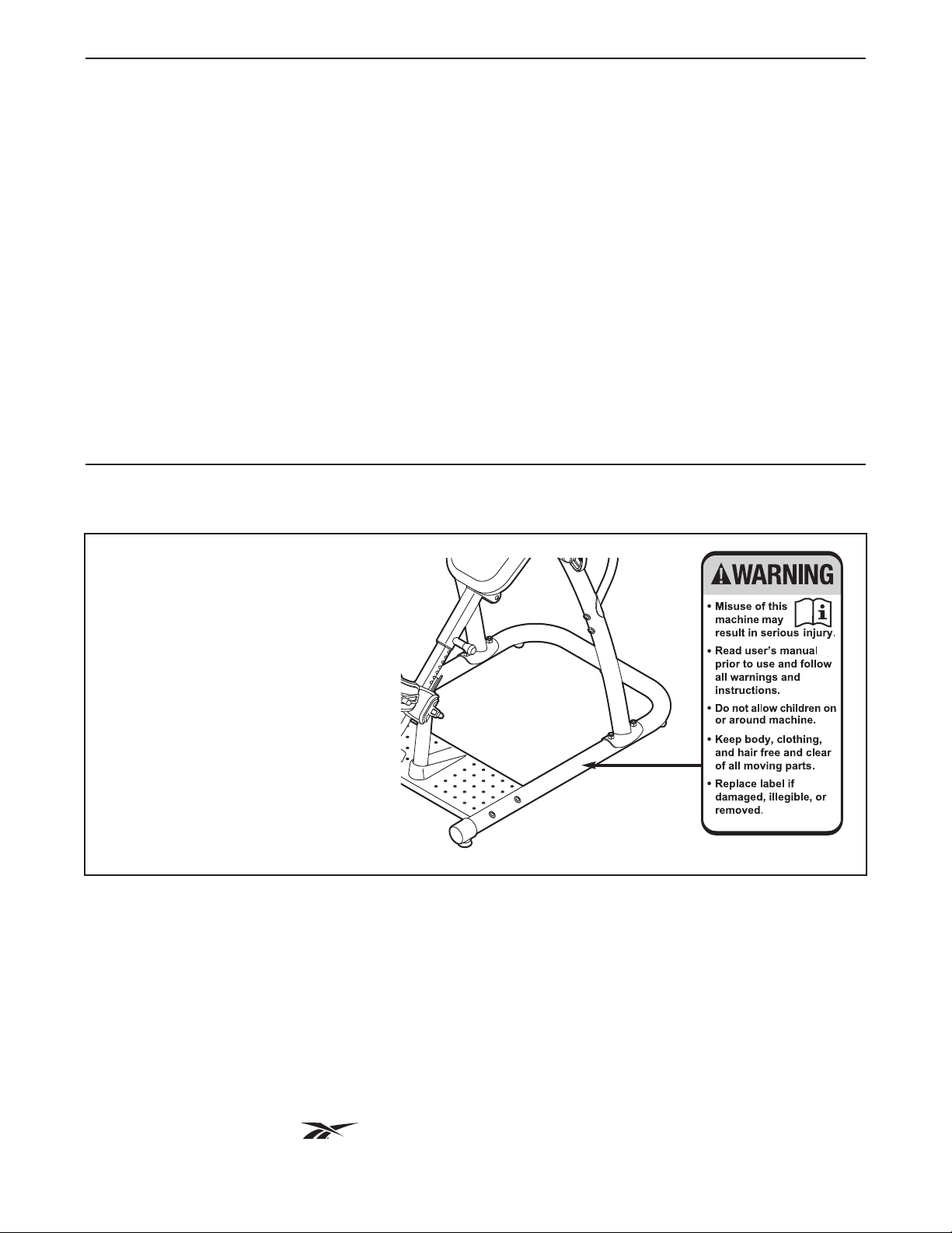
TABLE OF CONTENTS
WARNING DECAL PLACEMENT . . . . . . . . . . . . . . . . . . . . . . . . . . . . . . . . . . . . . . . . . . . . . . . . . . . . . . . . . . . . . .2
IMPORTANT PRECAUTIONS . . . . . . . . . . . . . . . . . . . . . . . . . . . . . . . . . . . . . . . . . . . . . . . . . . . . . . . . . . . . . . . . 3
BEFORE YOU BEGIN . . . . . . . . . . . . . . . . . . . . . . . . . . . . . . . . . . . . . . . . . . . . . . . . . . . . . . . . . . . . . . . . . . . . . . 4
PART IDENTIFICATION CHART . . . . . . . . . . . . . . . . . . . . . . . . . . . . . . . . . . . . . . . . . . . . . . . . . . . . . . . . . . . . . .5
SSEMBLY . . . . . . . . . . . . . . . . . . . . . . . . . . . . . . . . . . . . . . . . . . . . . . . . . . . . . . . . . . . . . . . . . . . . . . . . . . . . . . 6
A
ADJUSTMENT . . . . . . . . . . . . . . . . . . . . . . . . . . . . . . . . . . . . . . . . . . . . . . . . . . . . . . . . . . . . . . . . . . . . . . . . . . . 14
ROTATING ON THE INVERSION TABLE . . . . . . . . . . . . . . . . . . . . . . . . . . . . . . . . . . . . . . . . . . . . . . . . . . . . . . 16
DEVELOPING A PROGRAM . . . . . . . . . . . . . . . . . . . . . . . . . . . . . . . . . . . . . . . . . . . . . . . . . . . . . . . . . . . . . . . .17
PART LIST . . . . . . . . . . . . . . . . . . . . . . . . . . . . . . . . . . . . . . . . . . . . . . . . . . . . . . . . . . . . . . . . . . . . . . . . . . . . . .18
EXPLODED DRAWING . . . . . . . . . . . . . . . . . . . . . . . . . . . . . . . . . . . . . . . . . . . . . . . . . . . . . . . . . . . . . . . . . . . .19
ORDERING REPLACEMENT PARTS . . . . . . . . . . . . . . . . . . . . . . . . . . . . . . . . . . . . . . . . . . . . . . . . . .Back Cover
LIMITED WARRANTY . . . . . . . . . . . . . . . . . . . . . . . . . . . . . . . . . . . . . . . . . . . . . . . . . . . . . . . . . . . . . . Back Cover
WARNING DECAL PLACEMENT
The decal shown here has been
applied in the location shown. If the
decal is missing or illegible, call
the telephone number on the front
cover of this manual and request
a free replacement decal. Apply
the decal in the location shown.
Note: The decal may not be shown
at actual size.
REEBOK and the V
manufactured and distributed under license from Reebok International.
ector Logo are registered trademarks and service marks of Reebok.
2
This product is
Page 3

IMPORTANT PRECAUTIONS
WARNING: To reduce the risk of serious injury, read all important precautions and
instructions in this manual and all warnings on the inversion table before using the inversion table.
CON assumes no responsibility for personal injury or property damage sustained by or through the
I
use of the inversion table.
1. Before beginning any exercise program, consult your physician. This is especially important for persons over the age of 35 or persons with pre-existing health problems.
2. Use the inversion table only as described in
this manual.
3. It is the responsibility of the owner to ensure
that all users of the inversion table are adequately informed of all precautions.
4. The inversion table is intended for home use
only. Do not use the inversion table in any
commercial, rental, or institutional setting.
5. Keep the inversion table indoors, away from
moisture and dust. Do not put the inversion
table in a garage or covered patio, or near
water.
6. Use the inversion table only on a level surface. Cover the floor beneath the inversion
table to protect the floor.
7. Make sure that all parts are properly tightened each time the inversion table is used.
Replace any worn parts immediately.
Keep children under age 12 and pets away
8.
from the inversion table at all times.
The inversion table is designed to support a
9.
maximum user weight of 300 lbs. (136 kg). Do
not use weights with the inversion table.
10. Always wear athletic shoes with laces to help
secure your feet in the inversion table, and
for foot protection while exercising.
11. The inversion table should be used only by
persons 6 ft. 6 in. (198 cm) tall or less.
12. Keep hands and feet away from moving
parts.
13. Always make sure that the ankle lock is
secured snugly against your ankles and that
the short knob is fully tightened before you
use the inversion table.
14. Perform all activities on the inversion table in
a slow, controlled manner. Aggressive exercise can cause the inversion table to tip over.
15. Always exercise with a partner. Your partner
should be ready to return the backrest to the
upright position if you cannot complete the
rotation.
16. If you feel pain or dizziness while exercising,
stop immediately and begin cooling down.
17. Following is a list of factors and conditions
that may make inverting inadvisable (this list
is not exhaustive; it is intended only for reference). If one or more factors or conditions
apply to you, consult your physician before
using the inversion table.
• Pregnancy
• Hiatal hernia or ventral hernia
• Glaucoma, retinal detachment, or conjunctivitis
• High blood pressure, hypertension, or
recent stroke or transient ischemic attack
Heart or circulatory disorders for which you
•
are being treated
• Middle ear infection and extreme obesity
Spinal injury, cerebral sclerosis, or acutely
•
swollen joints
• Bone weakness (osteoporosis), recent
unhealed fractures, medullary pins, or surgically implanted orthopedic supports
• The use of anticoagulants, including high
doses of aspirin
3
Page 4
BEFORE YOU BEGIN
Thank you for selecting the versatile REEBOK
INVERSION SYSTEM inversion table. The inversion
table will increase your intervertebral dimension,
ecrease pressure on intervertebral discs, stretch and
d
relax your muscles, and temporarily relieve back pain
associated with the listed conditions.
For your benefit, read this manual carefully before
using the inversion table. If you have questions after
reading this manual, please see the front cover of this
manual. To help us assist you, note the product model
ASSEMBLED DIMENSIONS:
Height: 62 in. (157 cm)
Width: 36 in. (91 cm)
Depth: 66 in. (168 cm)
Handle
®
number and serial number before contacting us. The
model number and the location of the serial number
decal are shown on the front cover of this manual.
To avoid a registration fee for any service needed
under warranty, you must register the inversion
table at www.reebokservice.com/registration.
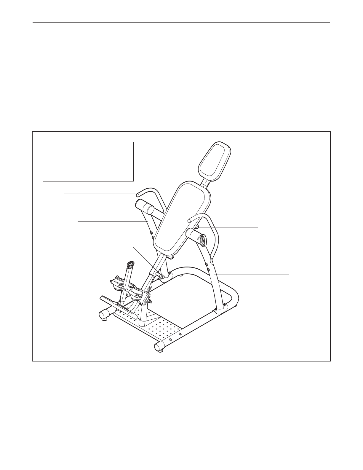
Before reading further, please review the drawing
below and familiarize yourself with the parts that are
labeled.
Headrest
Backrest
Right Frame
Short Adjustment Knob
Ankle Lock Assembly
Ankle Brace
Foot Plate
Long Adjustment Knob
Index Handle
Left Frame
4
Page 5
M10 Nylon
Locknut (65)
M8 Nylon
Locknut (72)
M6 Washer (62)
M4 x 15mm
Screw (58)
M10 x 85mm Button Bolt (51)
M10 x 95mm Button Bolt (73)
M6 x 18mm
Button Screw (55)
M6 x 55mm Button Screw (56)
M4 x 25mm
Screw (60)
M4 x 30mm
Screw (63)
M4 x 20mm
Screw (71)
M10 Curved Washer (50)
M10 Washer (68)
M10 x 35mm
Button Bolt (53)
M10 x 16mm
Button Screw (54)
M10 x 75mm Button Bolt (57)
M10 x 80mm Button Bolt (52)
M10 x 53mm Button Bolt (49)
M8 x 16mm
Button Bolt (61)
M5 x 25mm
Screw (59)
M10 Large Washer (64)
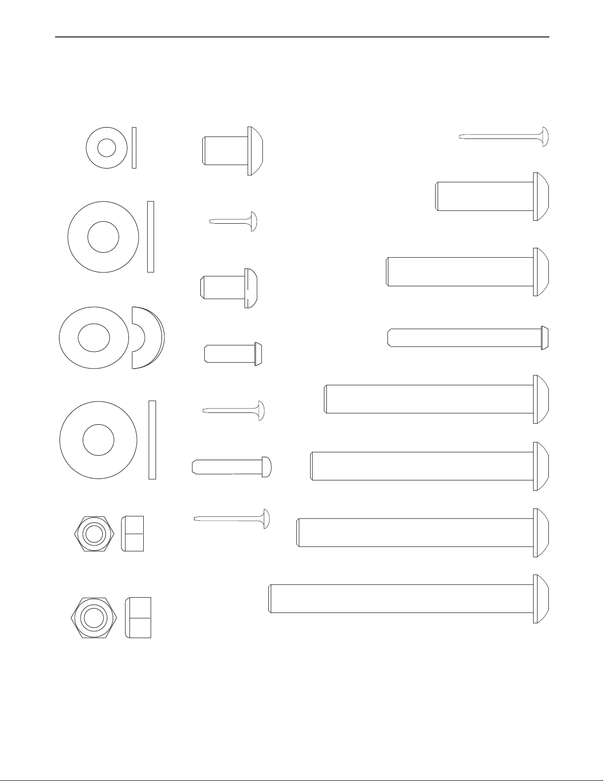
PART IDENTIFICATION CHART
See the drawings below to identify small parts used in assembly. The number in parentheses by each drawing is
the key number of the part, from the PART LIST near the end of this manual. Note: Some small parts may
have been pre-assembled. If a part is not in the parts bag, check to see if it has been preassembled.
5
Page 6
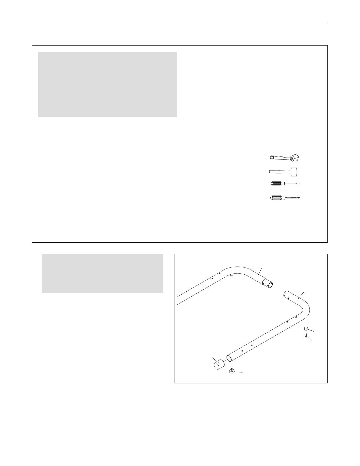
ASSEMBLY
Make Assembly Easier
This manual is designed to ensure that the
inversion table can be assembled successfully
by almost anyone. However, the inversion table
has many parts, and the assembly process will
take time. Most people find that if they set aside
plenty of time, assembly goes smoothly.
Before beginning assembly, carefully read the
following information and instructions:
• To hire an authorized service technician to
assemble the weight bench, call 1-800-445-2480.
aterials until assembly is completed.
m
For help identifying small parts, use the PART
•
IDENTIFICATION CHART on page 5.
• As you assemble the inversion table, make sure
that all parts are oriented as shown in the drawings.
• Tighten all parts as you assemble them, unless
instructed to do otherwise.
• The included grease and the following tools (not
included) may be required for assembly:
Two adjustable wrenches
• Assembly requires two persons.
• Because of its weight and size, the inversion
table should be assembled in the location where
it will be used. Make sure that there is enough
clearance to walk around the inversion table as
you assemble it.
• Place all parts in a cleared area and remove the
packing materials. Do not dispose of the packing
1.
Before beginning assembly, make sure
that you understand the information in
the box above. For help identifying
small parts, see page 5.
Press a 63mm Round Cap (40) onto the Left
Base (1).
Attach a Foot (42) to the Left Base (1) with an
M4 x 20mm Screw (71). Next, tighten a
Leveling Foot (41) into the Left Base.
Repeat this step for the Right Base (2).
One rubber mallet
One standard screwdriver
One Phillips screwdriver
Assembly may be more convenient if you have a
socket set, a set of open-end or closed-end
wrenches, or a set of ratchet wrenches.
1
2
1
42
71
40
41
6
Page 7
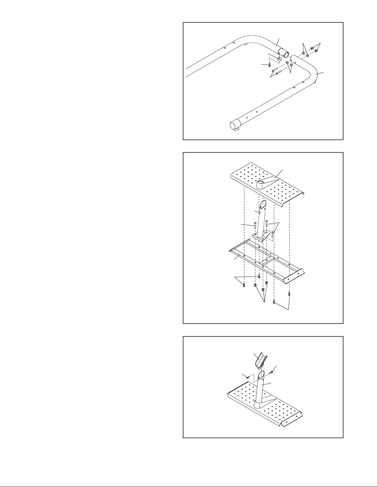
2. Attach the Left Base (1) to the Right Base (2)
with two M10 x 80mm Button Bolts (52), four
10 Curved Washers (50), and two M10
M
Nylon Locknuts (65).
Attach another Foot (42) to the Right Base (2)
with an M4 x 20mm Screw (71).
2
71
42
2
2
5
50
0
5
65
1
3. Attach the Support Leg (13) to the Center
Base (3) with three M10 x 35mm Button Bolts
(53) and three M10 Nylon Locknuts (65).
Attach the Base Plate (14) to the Center Base
(3) with four M5 x 25mm Screws (59).
3
14
13
53
3
59
65
53
59
4. Attach the Support Bracket (15) to the Support
Leg (13) with two M4 x 15mm Screws (58).
4
15
58
58
13
7
Page 8
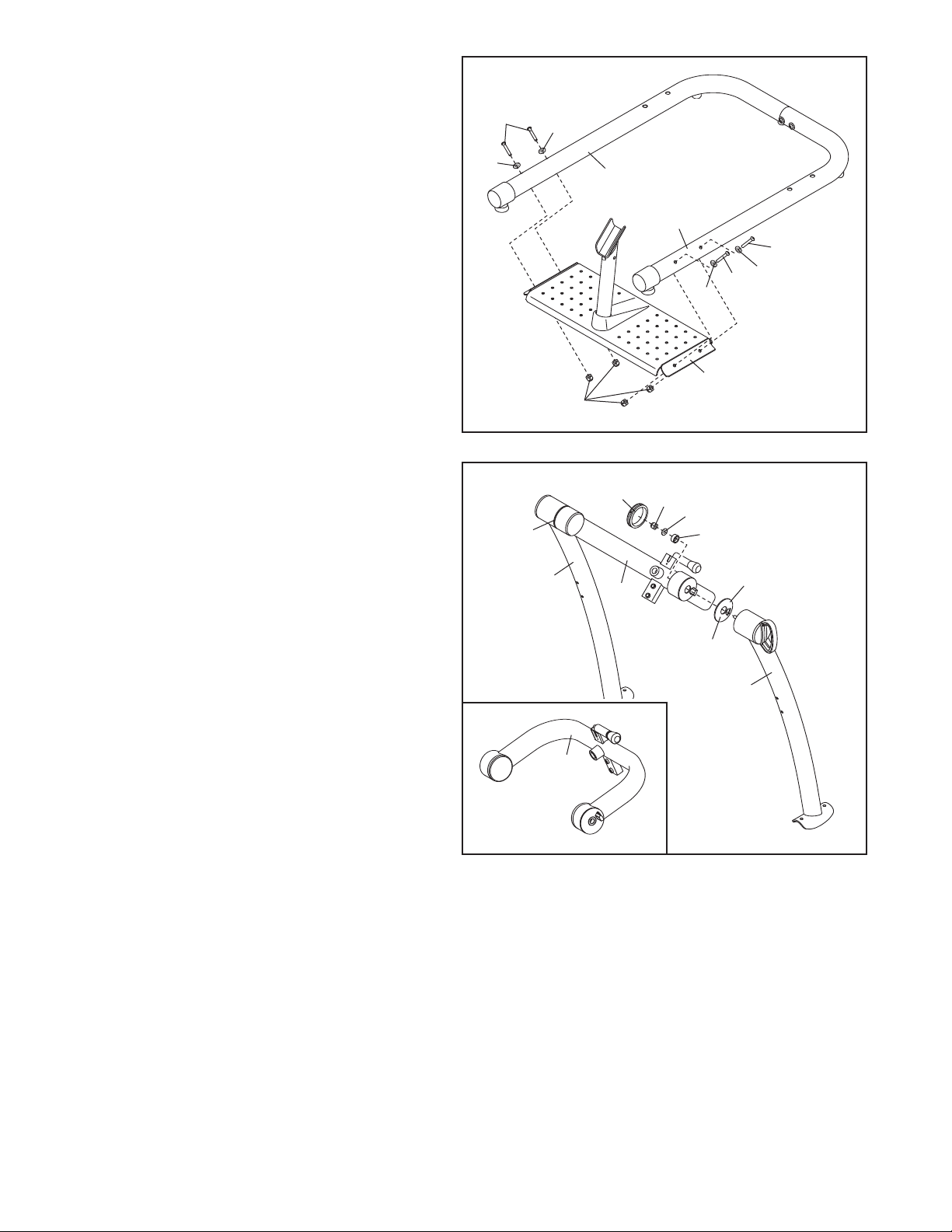
5. Attach the Center Base (3) to the Left and
Right Bases (1, 2) with four M10 x 80mm
utton Bolts (52), four M10 Curved Washers
B
(50), and four M10 Nylon Locknuts (65).
5
52
50
6. See the inset drawing. Identify the Center
Frame (7).
Apply some of the included grease to both
sides of the Left Large Spacer (31).
Attach the Left Large Spacer (31) and the Left
Frame (4) to the Center Frame (7) with an
M10 Nylon Locknut (65), an M10 Large
Washer (64), and a 29mm Spacer (48). Then,
press an 89mm Cap (32) into the Center
Frame.
Repeat this step with the Right Large
Spacer (70) and the Right Frame (5).
50
6
70
5
65
2
32
1
52
50
52
50
3
65
64
48
7
Grease
31
4
7
8
Page 9
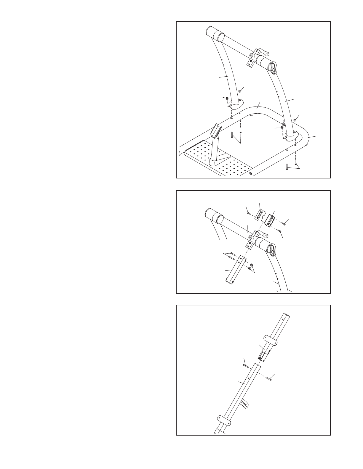
. Attach the Left and Right Frames (4, 5) to the
7
Left and Right Bases (1, 2) with four M10 x
85mm Button Bolts (51) and four M10 Nylon
Locknuts (65).
7
5
65
8. Attach the Top Cover (23) and the Bottom
Cover (24) to the Center Frame (7) with two
M4 x 15mm Screws (58) and an M4 x 30mm
Screw (63).
Attach the Center Frame Extension (6) to the
Center Frame (7) with two M10 x 53mm
Button Bolts (49) and two M10 Nylon Locknuts
(65).
65
51
8
49
58
2
65
23
24
7
4
65
1
51
63
58
Orient the Headrest Frame (9) and the
9.
Backrest Frame (8) as shown. Attach the
Headrest Frame to the Backrest Frame with
two M10 x 16mm Button Screws (54).
6
65
9
9
54
54
8
9
Page 10
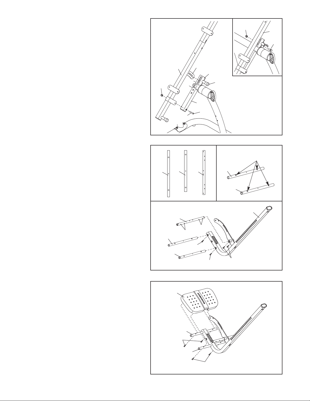
10. Apply a small amount of grease to an M10 x
95mm Button Bolt (73).
Pull the Long Adjustment Knob (37) out as far
s it will go. Insert the bracket on the Backrest
a
Frame (8) into the Top Cover (23). Next, attach
the Backrest Frame to the Center Frame
Extension (6) with the M10 x 95mm Button
Bolt (73) and an M10 Nylon Locknut (65).
Then, engage the Long Adjustment Knob into
one of the holes in the bracket.
See the inset drawing. Attach an M8 x 16mm
Button Bolt (61) and an M8 Nylon Locknut (72)
to the hole in the end of the bracket on the
Backrest Frame (8).
10
65
8
Grease
racket
B
6
73
23
37
2
7
8
61
11. See the left inset drawing. Identify the Top
Tube (16), the Bottom Tube (17), and the
Ankle Brace Tube (18); the Tubes have different lengths and holes in different positions.
Orient the Top Tube (16) and the Bottom
Tube (17) so that the largest holes are on top
(see the right inset drawing), and insert
them into the indicated holes in the Leg
Frame (10). Attach each Tube with an M4 x
15mm Screw (58).
Orient the Ankle Brace Tube (18) as shown,
and insert it into the Leg Frame (10). Attach
the Ankle Brace Tube with two M4 x 15mm
Screws (58).
Make sure that the M4 x 15mm Screws
(58) are tightened into the holes in the bottoms of the T
Set the Foot Plate (19) on the
12.
and the Bottom Tube (17).
four M4 x 25mm Screws (60) through the
ubes into the Foot Plate.
T
Screws yet.
ubes (16, 17, 18).
T
Finger tighten
Do not tighten the
op
ube (16)
T
11
12
16
16
17
19
17
18
Holes
18
Holes
58
58
Largest holes
must be on top
16
17
10
58
10
16
60
17
60
Page 11
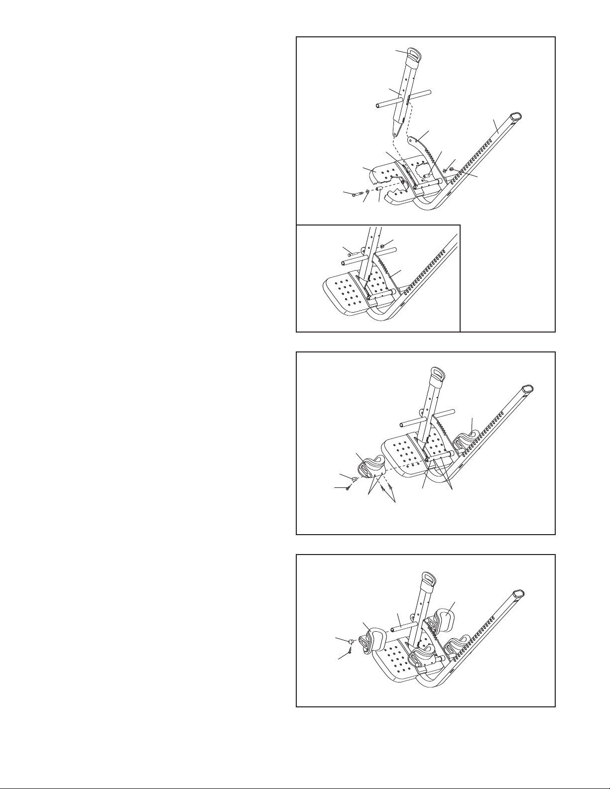
13. Slide the Lock Frame (11) onto the notched
bracket on the Leg Frame (10), and insert the
ower end of the Lock Frame into the slot in
l
the Foot Plate (19). Attach the Lock Frame
ith an M10 x 75mm Button Bolt (57), two
w
M10 Washers (68), two 16mm Spacers (46),
and an M10 Nylon Locknut (65) as shown.
Make sure that the Button Bolt is inserted
through the hole in the lower end of the
Lock Frame.
See step 12. Tighten the four M4 x 25mm
Screws (60).
Pull the Ankle Lock Assembly (33) upward
and pivot the Lock Frame (11) over the indicated notch in the bracket on the Leg Frame
(10). Release the Lock Handle and engage
the Lock Frame into the notch.
See the inset drawing. Attach an M8 x
16mm Button Bolt (61) and an M8 Nylon
Locknut (72) to the hole in the end of the
bracket on the Leg Frame (10).
13
57
61
19
68
Slot
46
11
33
72
10
Notch
10
6
4
68
65
14. Identify the two Rear Ankle Braces (34), which
have holes in the indicated locations.
Slide a Rear Ankle Brace (34) onto the Ankle
Brace Tube (18). Attach the Rear Ankle Brace
with two M4 x 15mm Screws (58).
that the Screws are tightened into the indicated holes in the Ankle Brace Tube. Next,
press a 19mm Round Cap (45) into the Ankle
Brace Tube, and attach the Round Cap with
an M4 x 15mm Screw (58).
Attach the other Rear
the Ankle Brace Tube (18) in the same way.
Slide a Front
15.
tube on the Lock Frame (11). Next, press a
19mm Round Cap (45) into the round tube,
and attach the Round Cap with an M4 x 15mm
Screw (58).
Attach the other Front
the same way.
Ankle Brace (22) onto the round
Ankle Brace (34) to
Ankle Brace (22) in
Make sure
14
15
58
45
45
34
Holes
22
11
58
18
34
Holes
22
11
58
Page 12

6. Pull the Short Adjustment Knob (74) out as far
1
as it will go, and insert the end of the Leg
Frame (10) a few inches into the Backrest
Frame (8).
ee the inset drawing.Press the round tab
S
on the Leg Frame Bushing (38), and press the
Leg Frame Bushing upward into the Backrest
Frame (8).
in the indicated hole in the Backrest Frame.
Then, slide the Leg Frame (10) farther into the
Backrest Frame (8), and engage the Short
Adjustment Knob (74) into one of the holes in
the Leg Frame.
Make sure that the round tab is
16
8
ole
H
8
3
Ta b
0
1
8
10
74
Holes
17. Attach the Headrest (20) to the Headrest
Frame (9) with two M6 x 18mm Button Screws
(55), an M6 x 55mm Button Screw (56), and
three M6 Washers (62).
Attach the Backrest (21) to the Backrest
Frame (8) in the same way.
17
20
21
8
9
62
56
55
62
12
Page 13
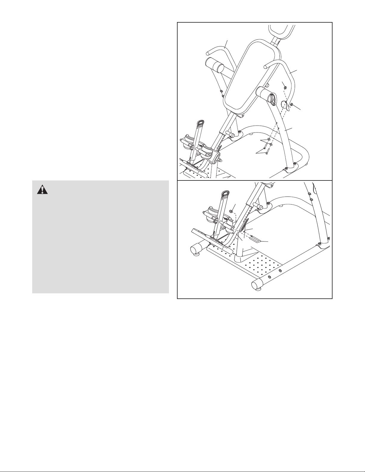
18. Attach a Handle (12) to the Left Frame (4) with
two M10 x 80mm Button Bolts (52), two M10
urved Washers (50), and two M10 Nylon
C
Locknuts (65).
Attach the other Handle (12) in the same
way.
Make sure that all parts are properly tightened before you use the inversion table.
WARNING:
HOW TO LOCK THE INVERSION TABLE
FOR STORE DISPLAY OR TO PREVENT
UNSUPERVISED USE
When the inversion table is displayed in a
store, or when it is not in use, it should be
locked to prevent unsupervised use. First,
insert the threaded end of the Lock Pin (35)
into the Support Leg (13), and position the
other end of the Lock Pin on top of the Leg
Frame (10). Then, tighten an M10 Nylon
Locknut (65) onto the Lock Pin.
18
12
65
10
52
50
13
35
65
2
1
65
4
13
Page 14
ADJUSTMENT
2
2
1
Hole A—Least responsive
Holes B, C—Moderately responsive
Hole D—Most responsive
#Beginner/partial inversion
*Advanced/full inversion
D
This section explains how to adjust the inversion table. See DEVELOPING A PROGRAM on page 17 for important information about how to get the most benefit from the inversion table.
Make sure that all parts are properly tightened each time you use the inversion table. Replace any worn parts
immediately. The inversion table can be cleaned with a damp cloth and a mild, non-abrasive detergent.
solvents to clean the inversion table.
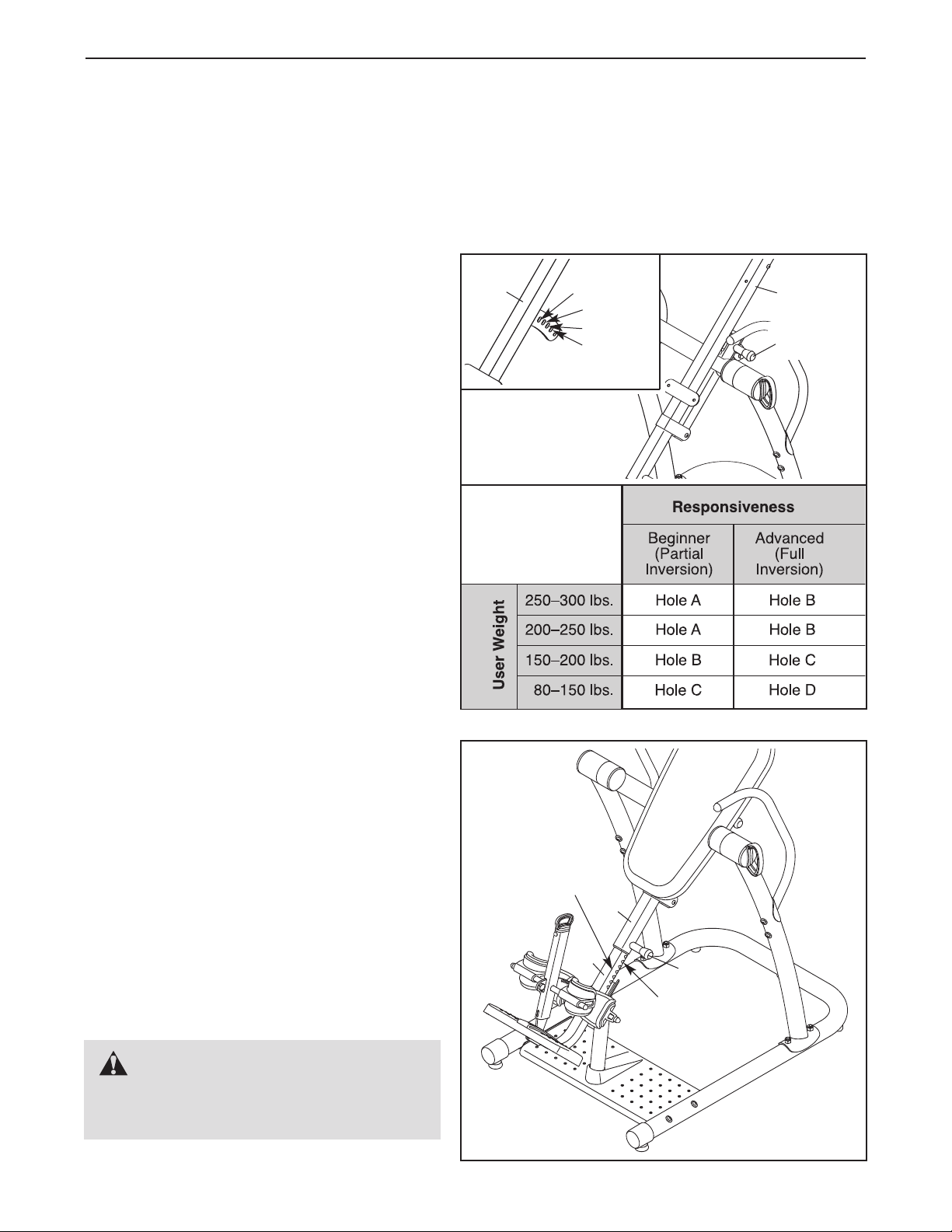
SELECTING THE BACKREST FRAME POSITION
See the inset drawing. The bracket on the
Backrest Frame (8) has four adjustment holes. The
correct hole to use will depend on your body
weight and the desired level of responsiveness.
See the chart to determine which hole to use. For
example, if you weigh between 200 and 250
pounds and you are a beginning user, the chart
recommends that you use hole A.
To adjust the Backrest Frame (8), first pull the Long
Adjustment Knob (37) out as far as it will go. Move
the Backrest Frame and engage the Long
Adjustment Knob into the desired hole in the bracket on the Backrest Frame.
8
Note: 1 lb. = 2.2 kg
Hole A
Hole B
Hole C
Hole D
Do not use
8
37
Try the inversion table with the Backrest Frame (8)
adjusted to each position to determine which one
is best for you.
ADJUSTING THE LEG FRAME
The length of the Leg Frame (10) can be adjusted
to correspond to your height. Pull the Short
Adjustment Knob (74) out as far as it will go. Slide
the Leg Frame into or out of the Backrest Frame
(8) so that the first or second measurement
greater than your height is covered by the
Backrest Frame.
Adjustment Knob into adjustment holes in the Leg
Frame and the Backrest Frame.
Use the inversion table with the Leg Frame (10)
adjusted to a few different lengths to determine
which length is best for you.
Then, engage the Short
Height
Measurements
8
10
74
Adjustment
Hole
WARNING: The inversion table
is designed to be used by persons 6 ft. 6
in. (198 cm) tall or less.
14
Page 15
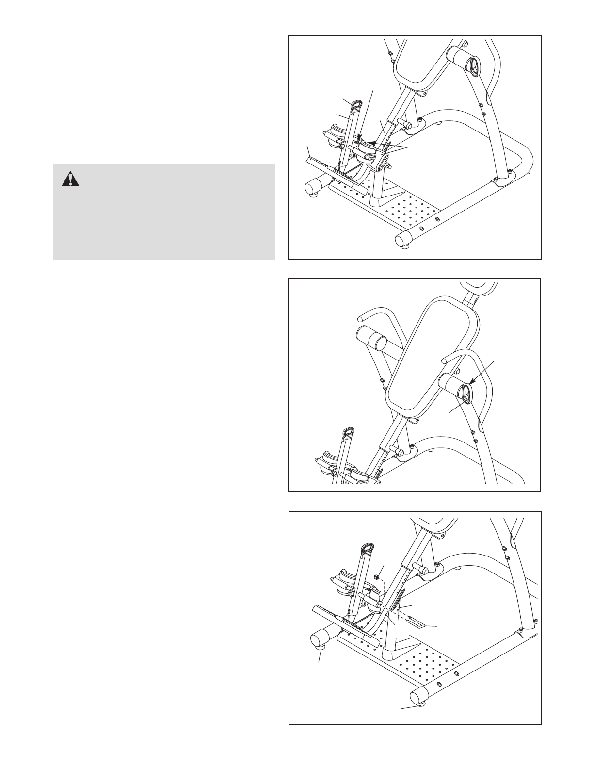
USING THE ANKLE LOCK
o secure your ankles in the inversion table, pull
T
the Ankle Lock Assembly (33) out as far as it will
o, and move the Lock Frame (11) away from the
g
Leg Frame (10). Stand on the Foot Plate (19), with
the backs of your legs against the Rear Ankle
Braces (34). Then, push the Lock Frame against
your ankles and engage the Lock Handle into a
notch in the Leg Frame.
WARNING: Always make sure
that the Lock Frame (11) is secured snugly
against your ankles before using the inversion table. Always wear athletic shoes with
laces to help secure your feet in the inversion table.
SETTING THE INVERSION ANGLE
The inversion table can be set to rotate between
15° and 90°, in 15° increments. To set the inversion angle, pull the Index Handle (25) out as far as
it will go, and turn the Index Handle until the arrow
on top of the Index Handle points to the desired
degree setting. Then, release the Index Handle;
make sure that the Index Handle is fully
engaged.
19
11
33
otches
N
0
1
34
Arrow
LEVELING THE INVERSION TABLE
If the inversion table rocks slightly on your floor,
turn one or both of the Leveling Feet (41) until the
inversion table is level.
LOCKING THE INVERSION TABLE
T
o lock the inversion table when you are not using
it, insert the threaded end of the Lock Pin (35) into
the Support Leg (13), and position the other end of
the Lock Pin on top of the Leg Frame (10). Then,
tighten an M10 Nylon Locknut (65) onto the Lock
Pin.
41
65
10
25
13
35
15
41
Page 16

ROTATING ON THE INVERSION TABLE
This section explains how to rotate back on the inversion table, and then return to the starting position. Before
using the inversion table, see the ADJUSTMENT section starting on page 14 to correctly set up the
inversion table.
table.
It may be helpful to have a second person ready to assist you as you learn to use the inversion
ROTATING BACK ON THE INVERSION TABLE
To rotate back on the inversion table, slowly lift your
arms over your head until you reach the desired position. The speed at which you lift your arms will determine how quickly the inversion table will rotate. Rest
your arms in a comfortable position that does not
cause the inversion table to rotate. Note: The inversion
table will rotate only to the degree setting set by the
index handle.
ROTATING UP ON THE INVERSION TABLE
To return to the starting position, move your hands
toward your waist until you rotate to a horizontal position. Rest in a horizontal position for 30 to 60 seconds
before rotating to the starting position. This will allow
your body to readjust. Return to the starting position
slowly. Dizziness after using the inversion table is an
indication that you have returned to the starting position
too quickly.
To rotate up from the fully inverted position, pull yourself up using the handles.
Do not sit up to return to the starting position.
16
Page 17

DEVELOPING A PROGRAM
This section contains information and suggestions about using the inversion table. Make sure that all parts are
properly tightened each time you use the inversion table. Replace any worn parts immediately. See the ADJUST-
MENT section starting on page 14 to identify parts referred to in this section.
BENEFITING FROM USING THE INVERSION TABLE
If you feel nauseated while using the inversion table,
return to the starting position. Note that it may take a
few weeks of use for your inner ear to become accustom to being inverted.
Do not use the inversion table right after you have
eaten.
Moving while using the inversion table may make it a
more comfortable experience, and may help joints and
muscles stretch and relax. Always move in a slow, controlled manner.
The greater the angle at which the inversion table is
used, the shorter the time that you should rotate back
before rotating up. Increase the amount of inverted time
and the angle of use gradually.
Always pay attention to how your body feels as you use
the inversion table. Increase the level of intensity only
as it is comfortable for you. When you feel like you have
had enough, return to the starting position.
BEGINNER PROGRAM
The following are suggestions for persons who are just
starting to use the inversion table.
INTERMEDIATE PROGRAM
The following are suggestions for persons who have
become comfortable using the inversion table as
described under the BEGINNER PROGRAM.
Increase the angle to which the inversion table can
rotate, as it is comfortable. Adjust the index handle to
allow the inversion table to rotate to up to 60°, a few
degrees at a time.
Start to do gentle stretching while using the inversion
table.
Gradually increase the amount of time that you use
the inversion table to ten minutes or more, two or
three times a day. Routines can be varied from rotating back for one or two minutes and then up for 30
seconds, to rotating back and up for equal amounts of
time.
FULL INVERSION PROGRAM
The following are suggestions for persons who have
become comfortable using the inversion table as
described under the INTERMEDIATE PROGRAM and
desire to rotate to greater angles. Note that all the
benefits of inversion can be gained by rotating to 60°.
Do not attempt to do sit-ups.
Set the index handle to allow the backrest frame to
rotate to 15° or less for the first one or two weeks. This
will allow your body time to adjust to the change in
gravitational pull.
Use the inversion table for one or two minutes at a
time, two or three times a day.
Stay inverted only for as long as it is comfortable. This
may be only a few seconds at first.
Increase the angle to which the inversion table can
rotate, as it is comfortable. Adjust the index handle to
allow the inversion table to rotate until it comes in contact with the center frame.
Adjust the backrest frame so that the long adjustment
knob is in the top hole (see SELECTING THE BACKREST FRAME POSITION on page 14). If you weigh
220 lbs. (100 kg) or more, adjust the long adjustment
knob to the center hole in the backrest frame. Rotate
back and up as described on page 16.
17
Page 18

PART LIST—Model No. RBBE2057.0 R1207A
Key No. Qty. Description Key No. Qty. Description
1 1 Left Base
2 1 Right Base
3 1 Center Base
4 1 Left Frame
5 1 Right Frame
6 1 Center Frame Extension
7 1 Center Frame
8 1 Backrest Frame
9 1 Headrest Frame
10 1 Leg Frame
11 1 Lock Frame
12 2 Handle
13 1 Support Leg
14 1 Base
15 1 Support Bracket
16 1 Top Tube
17 1 Bottom Tube
18 1 Ankle Brace Tube
19 1 Foot Plate
20 1 Headrest
21 1 Backrest
22 2 Front Ankle Brace
23 1 Top Cover
24 1 Bottom Cover
25 1 Index Handle
26 1 Index Ring
27 1 Cup Washer
28 1 Small Spring
29 1 Cup Bushing
30 1 Index Cup
31 1 Left Large Spacer
32 3 89mm Cap
33 1 Ankle Lock Assembly
34 2 Rear Ankle Brace
35 1 Lock Pin
36
37 1 Long Adjustment Knob
38 1 Leg Frame Bushing
39 2 42mm x 70mm Cap
1 Bumper
40 2 63mm Round Cap
41 2 Leveling Foot
42 3 Foot
43 1 M6 Nut
44 2 32mm Round Cap
45 4 19mm Round Cap
46 2 16mm Spacer
47 2 Pivot Bushing
48 2 29mm Spacer
49 2 M10 x 53mm Button Bolt
50 12 M10 Curved Washer
51 4 M10 x 85mm Button Bolt
52 10 M10 x 80mm Button Bolt
53 3 M10 x 35mm Button Bolt
54 2 M10 x 16mm Button Screw
55 4 M6 x 18mm Button Screw
56 2 M6 x 55mm Button Screw
57 1 M10 x 75mm Button Bolt
58 20 M4 x 15mm Screw
59 4 M5 x 25mm Screw
60 4 M4 x 25mm Screw
61 2 M8 x 16mm Button Bolt
62 7 M6 Washer
63 1 M4 x 30mm Screw
64 2 M10 Large Washer
65 24 M10 Nylon Locknut
66 1 M6 x 15mm Screw
67 2 M5 x 15mm Screw
68 2 M10 Washer
69 1 30mm x 60mm Cap
70 1 Right Large Spacer
71 3 M4 x 20mm Screw
72 2 M8 Nylon Locknut
73 1 M10 x 95mm Button Bolt
74 1 Short Adjustment Knob
75
* – User’s Manual
* – Hex Key
* – Grease Packet
1 M6 x 60mm Button Bolt
Note: Specifications are subject to change without notice. See the back cover of this manual for information
about ordering replacement parts. *These parts are not illustrated.
18
Page 19
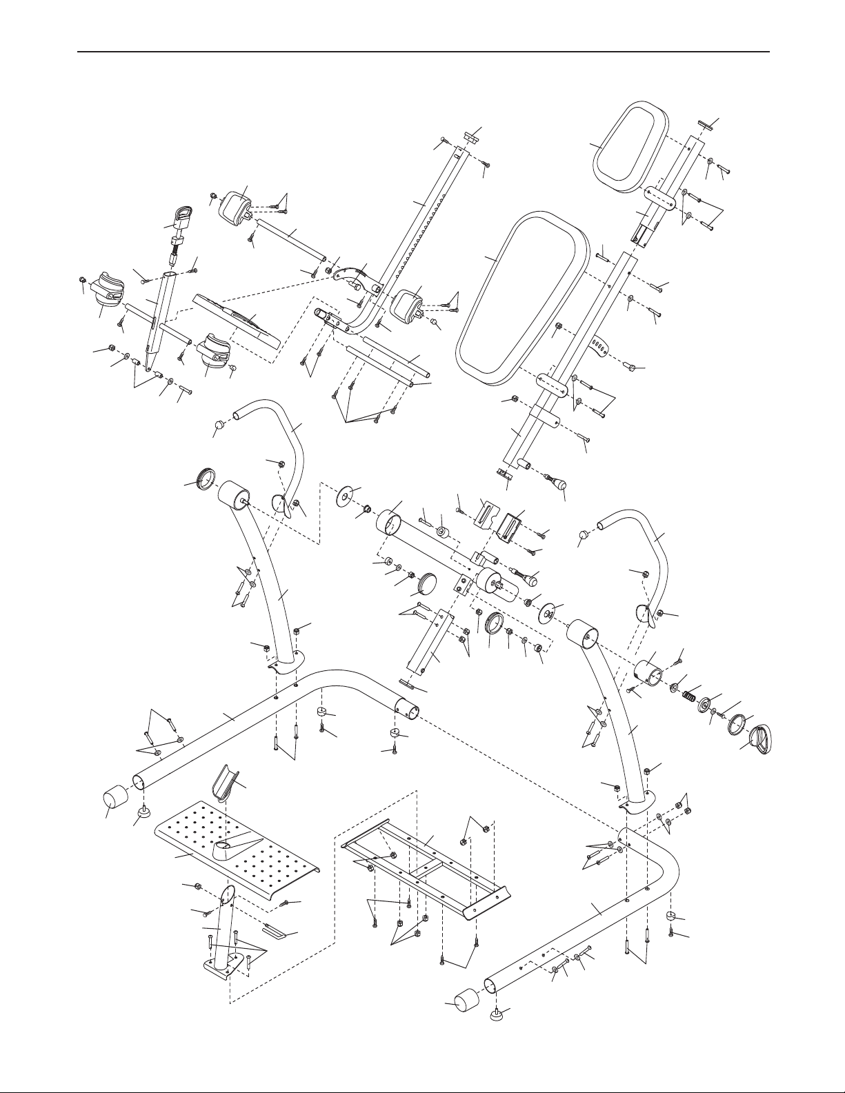
EXPLODED DRAWING—Model No. RBBE2057.0 R1207A
1
2
3
4
5
6
7
8
9
10
11
12
12
13
14
15
16
17
18
19
2
0
21
34
34
22
22
23
24
25
26
27
28
29
30
31
32
32
70
32
33
6
9
3
9
38
40
40
41
41
42
42
42
74
37
44
44
46
45
45
45
45
47
48
48
47
39
36
65
65
52
52
52
52
52
52
65
73
55
56
55
56
54
57
58
58
5
8
58
75
58
49
71
71
59
59
60
61
58
50
50
50
50
50
50
50
62
62
65
65
51
65
65
65
65
65
65
72
65
65
65
65
53
54
58
58
58
61
72
58
58
68
68
51
65
65
65
67
67
66
64
64
43
58
58
63
58
62
62
62
58
58
58
35
71
19
Page 20

ORDERING REPLACEMENT PARTS
To order replacement parts, please see the front cover of this manual. To help us assist you, be prepared to provide the following information when contacting us:
• the model number and serial number of the product (see the front cover of the manual)
the name of the product (see the front cover of this manual)
•
• the key number and description of the part(s) (see the PART LIST and the EXPLODED DRAWING near the
end of this manual)
LIMITED WARRANTY
ICON Health & Fitness, Inc. (ICON) warrants this product to be free from defects in workmanship and material, under normal use and service conditions, for a period of ninety (90) days from the date of purchase. This
warranty extends only to the original purchaser. ICON's obligation under this warranty is limited to replacing
or repairing, at ICON's option, the product through one of its authorized service centers. All repairs for which
warranty claims are made must be pre-authorized by ICON. If the product is shipped to a service center,
freight charges to and from the service center will be the customer’s responsibility. For in-home service, the
customer will be responsible for a minimal trip charge. This warranty does not extend to any product or damage to a product caused by or attributable to freight damage, abuse, misuse, improper or abnormal usage or
repairs not provided by an ICON authorized service center; products used for commercial or rental purposes;
or products used as store display models. No other warranty beyond that specifically set forth above is authorized by ICON.
ICON is not responsible or liable for indirect, special or consequential damages arising out of or in connection
with the use or performance of the product or damages with respect to any economic loss, loss of property,
loss of revenues or profits, loss of enjoyment or use, costs of removal or installation or other consequential
damages of whatsoever nature. Some states do not allow the exclusion or limitation of incidental or consequential damages. Accordingly, the above limitation may not apply to you.
The warranty extended hereunder is in lieu of any and all other warranties and any implied warranties of merchantability or fitness for a particular purpose is limited in its scope and duration to the terms set forth herein.
Some states do not allow limitations on how long an implied warranty lasts. Accordingly
may not apply to you.
, the above limitation
This warranty gives you specific legal rights.
TH & FITNESS, INC., 1500 S. 1000 W., LOGAN, UT 84321-9813
Part No.
263046
ICON HEAL
R1207A Printed in China © 2007 ICON IP, Inc.
ou may also have other rights which vary from state to state.
Y
 Loading...