

Reebok Exercise Bike User Manual

Contents
Safety Precautions 4
Hardware Pa cking List 5
Parts List 6
Parts List 7
Exploded Diagram 8
Assembly Diagram 9
Assembly Instructions 10
Computer Instruction- Console 13
LCD Display Function 14
Warning
Before beginning this or any exercise program , consult
your physician. This is especially important for persons who
have not exercised regularly before or persons with preexisting
health problems. Read all instructions before using. Reebok Sport
assumes no responsibility for personal i n jury or property damage
sustained by or through the use of this product.

4
SAFETY PRECAUTIONS
Before beginning any exercise program, you should consult with your doctor. It is
recommended that you under go a complete physical examination.
Work within your recommended exercise level, do not work to exhaustion. If you
feel any pain or abnormal systems, stop your workout immediately. Consult your
physician immediately.
Use the equipment on a solid, flat level surface with a protective cover fo r your
floor or carpet. For safety, the equipment should have at least 0.5 meter off free
space all around it.
Do not allow children to play on or around your bike. Keep hands away from
moving parts.
Check your bike prior to exercising to ensure that all parts are assembled, and
nuts, bolts, pedals and the saddle are tightened before every use.
Always check to see that seat is securely fastened before using your bike.
Always wear proper workout clothing and shoes when using your bike. Do not
wear loose clothing. Do not wear shoes with leather sole or high heels.
The equipment has been complying to EN957 under class H.C. Suitable for
domestic, home use only. Maximum weight of user is to be 100kg. Breaking is
speed independent.
IMPORTANT
Please read instructions carefully before assembling.
Please remove all the parts from the carton and identify them against the parts
list to ensure you have all the parts. If you are missing any parts please call our
Technical Support Line: 0871 474 2614
Do not destroy the carton until you have assembled the bike completely.
Always use the equipment as indicated. If you find any defective components
whilst assembling or checking the equipment, or if you hear any unusual noise
coming from the equipment during use, stop. Do not use the equipment until the
problem has been rectified. Call the Technical Support Line: 0871 474 2614
5
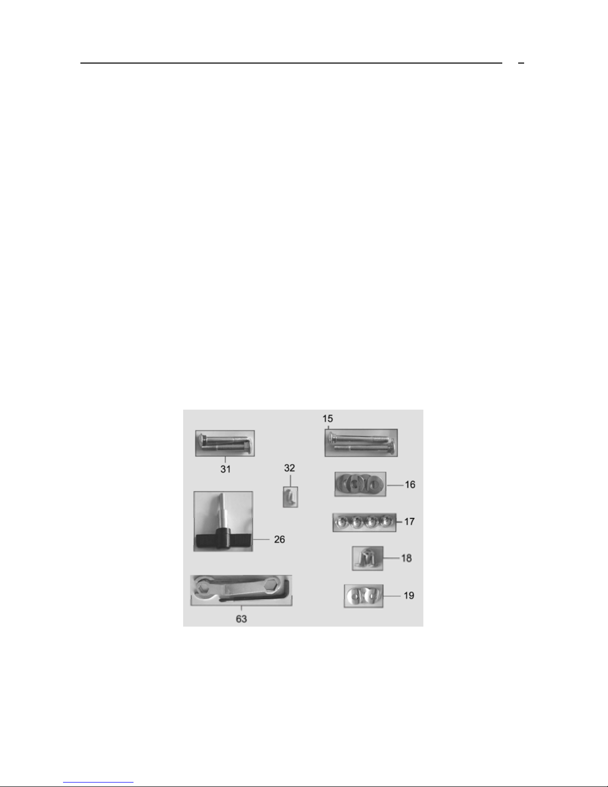
HARDWARE PARTS LIST
Key Description Quantity
15. Carriage Bolt M10*75 2
16. Curve Washer Φ10.5*Φ25*T1.5 4
17. Domed Nut M10 4
18. Allen Bolt M8*15 3
19. Curve Washer Φ10.5*Φ25*T1.2 3
26. T Type Knob 1
31. Carriage Bolt M10*60 2
32. ScrewΦ5*15 2
63. Box Wrench 13/17 1
63. Spanner 15 1
63. Allen Key L6 1
IF YOU’RE MISSING ANY PARTS PLEASE CALL TECHICAL SUPPORT ON
0871 474 2614 OR MAIL: techsupport@rfe.co.uk

6
PARTS LIST
No. PART NAME Q'TY
1 Main frame 1
2 Front Stabilizer 1
3 Rear Stabilizer 1
4 Front Post 1
5 Handlebar W/Grip 1
6 Computer 1
7 Seat Post 1
8 Seat 1
9 Left Pedal 1
10 Right Pedal 1
11 Quick Release Adjustment Knob 1
12 Φ16 Flat Washer 3
13 Spring Washer 3
14 M8 Nylon Lock Nut 3
15 M10x75mm Carriage Bolt 2
16 Φ25 Curve Washer 4
17 M10 Domed Nut 4
18 M8*15mm Allen Bolt 3
19 Φ22 Curve Washer 3
20 Saddle Stem Cover 1
21 Upper Computer Wire 1
22 Adapter 1
23 Upper Computer Wire 1
24 Hand Pulse Wire 1
25 Crank Arm 1
26 T Knob 1
27 Allen Bolt M8*20 1
28 Front Stabilizer End Cap 2
29 Rear Stabilizer End Cap 2
30 Clamp 1
31 M10x60mm Carriage Bolt 2
32 Screw Φ5*15 1
33 Bottle Holder 1
34 Screw Φ5*10 1
35 Lower Computer Wire 1
36 B.B. set 1
37 Crank Wheel 1
38 Magnetite (Reed Switch) 1
39 Belt 1
40 Magnetite Holder 1
41 Hex Bolt M8*35 1
42 Hex Nut M8 1
43 Spring 1
44 Flat Washer 2
45 C ring 2

7
PARTS LIST
No. PART NAME Q'TY
46 Washer φ8.5*φ16*T1.5 2
47 Nylon Nut M8 1
48 Short Spacer 1
49 Allen Bolt M8*15 2
50 L-shape Support 1
51 Bolt M6*10 2
52 Idler Support 1
53 Bearing Set 1
54 Flat Washerφ8.5xφ16xT1.5 1
55 Nylon Lock Nut M6 1
56 Screw φ5*8 2
57 Nylon Lock Nut M8 1
58 Screw for Idler 1
59 Washer for Idler 1
60 Flat Washerφ8.5xφ13xT1.5 2
61 Bearing 608Z 1
62 Idler Wheel 1
63 Bushing for Idler 1
64 Idler Spring 1
65 Fly Wheel 1
66 Bearing 6303Z 2
67 Axle for Fly Wheel 1
68 One way Bearing 1
69 Bearing Set 1
70 C-shape Clip 2
71 Clip φ17 1
72 Split Washer φ6 5
73 Screw M6*12 6
74 Bearing 6003Z 3
75 Bearing Set 1
76 Sensor 2
77 Philip Screw φ4*15 2
78 Left Chain Cover 1
79 Right Chain Cover 1
80 Crank Cap 2
81 Philip Screw φ5*15 10
82 Philip Screw φ4*20 1
83 Foam Grip 2
84 Handlebar Endcap 2
85 Hex Screw M8 * 25 2
86 Plastic Spacer 1
87 Crank Endcap 2
88 Read Switch 1
89 Nail 1
 Loading...