

Reebok 306960 Owner's Manual
Model No. 30696.0
www.reebokfitness.com
Visit our website at
Serial No.
Write the serial number in the space
above for future reference.
Serial
Number
Decal
QUESTIONS?
As a manufacturer, we are committed to providing complete
customer satisfaction. If you
have questions, or if parts are
damaged or missing, PLEASE
CONTACT OUR CUSTOMER
SERVICE DEPARTMENT
DIRECTLY.
USER'S MANUAL
CALL TOLL-FREE:
1-888-936-4266
Mon.–Fri., 8:00 until 17:00 ET
(excluding holidays)
OR E-MAIL US:
customerservice@iconcanada.ca
CAUTION
Read all precautions and instructions in this manual before using
this equipment. Keep this manual
for future reference.
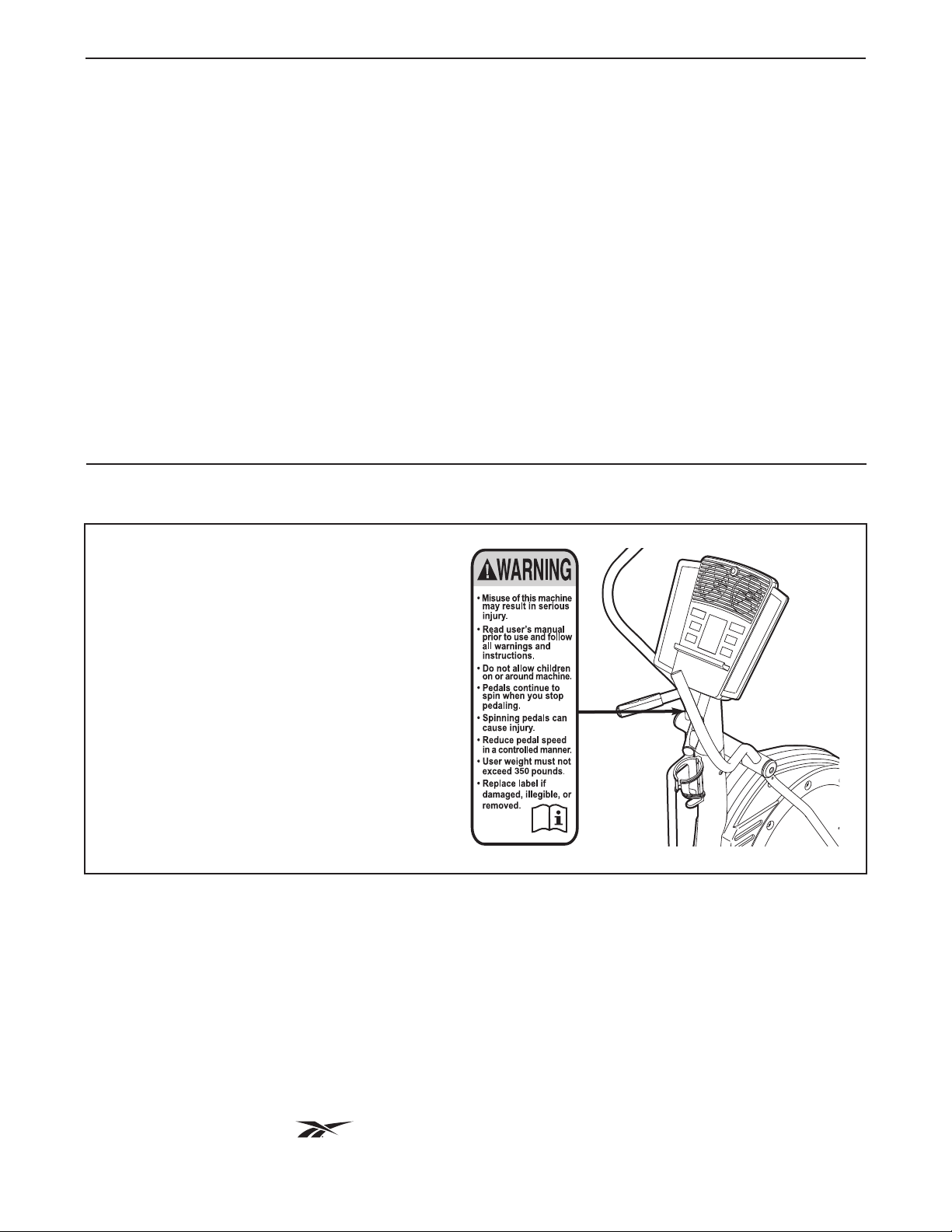
TABLE OF CONTENTS
WARNING DECAL PLACEMENT . . . . . . . . . . . . . . . . . . . . . . . . . . . . . . . . . . . . . . . . . . . . . . . . . . . . . . . . . . . . . .2
MPORTANT PRECAUTIONS . . . . . . . . . . . . . . . . . . . . . . . . . . . . . . . . . . . . . . . . . . . . . . . . . . . . . . . . . . . . . . . .3
I
BEFORE YOU BEGIN . . . . . . . . . . . . . . . . . . . . . . . . . . . . . . . . . . . . . . . . . . . . . . . . . . . . . . . . . . . . . . . . . . . . . .4
ASSEMBLY . . . . . . . . . . . . . . . . . . . . . . . . . . . . . . . . . . . . . . . . . . . . . . . . . . . . . . . . . . . . . . . . . . . . . . . . . . . . . . .5
HOW TO USE THE CHEST PULSE SENSOR . . . . . . . . . . . . . . . . . . . . . . . . . . . . . . . . . . . . . . . . . . . . . . . . . . .11
HOW TO USE THE ELLIPTICAL EXERCISER . . . . . . . . . . . . . . . . . . . . . . . . . . . . . . . . . . . . . . . . . . . . . . . . . .13
MAINTENANCE AND TROUBLESHOOTING . . . . . . . . . . . . . . . . . . . . . . . . . . . . . . . . . . . . . . . . . . . . . . . . . . .20
EXERCISE GUIDELINES . . . . . . . . . . . . . . . . . . . . . . . . . . . . . . . . . . . . . . . . . . . . . . . . . . . . . . . . . . . . . . . . . . .21
PART LIST . . . . . . . . . . . . . . . . . . . . . . . . . . . . . . . . . . . . . . . . . . . . . . . . . . . . . . . . . . . . . . . . . . . . . . . . . . . . . .24
EXPLODED DRAWING . . . . . . . . . . . . . . . . . . . . . . . . . . . . . . . . . . . . . . . . . . . . . . . . . . . . . . . . . . . . . . . . . . . .25
ORDERING REPLACEMENT PARTS . . . . . . . . . . . . . . . . . . . . . . . . . . . . . . . . . . . . . . . . . . . . . . . . . .Back Cover
LIMITED WARRANTY . . . . . . . . . . . . . . . . . . . . . . . . . . . . . . . . . . . . . . . . . . . . . . . . . . . . . . . . . . . . . .Back Cover
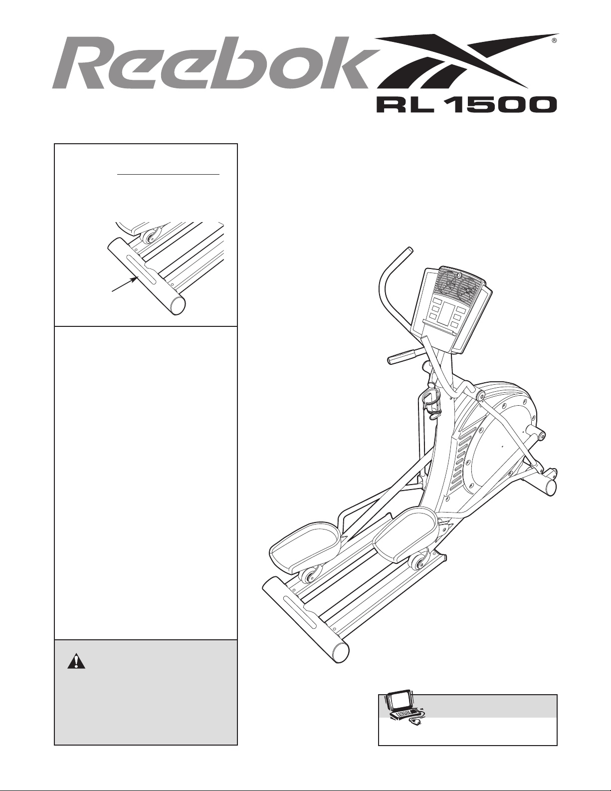
WARNING DECAL PLACEMENT
This drawing shows the location(s) of the
warning decal(s). If a decal is missing or
illegible, see the front cover of this
manual and request a free replacement
decal. Apply the decal in the location
shown. Note: The decal(s) may not be
shown at actual size.
REEBOK and the Vector Logo are registered trademarks and service marks of Reebok. This product is
manufactured and distributed under license from Reebok International.
2

IMPORTANT PRECAUTIONS
WARNING: To reduce the risk of serious injury, read all important precautions and in-
structions in this manual and all warnings on your elliptical exerciser before using your elliptical exerciser. ICON assumes no responsibility for personal injury or property damage sustained by or
through the use of this product.
1. Before beginning any exercise program, consult your physician. This is especially important for persons over the age of 35 or persons with pre-existing health problems.
2. It is the responsibility of the owner to ensure
that all users of the elliptical exerciser are
adequately informed of all precautions.
3. Your elliptical exerciser is intended for home
use only. Do not use your elliptical exerciser
in a commercial, rental, or institutional setting.
4. Keep your elliptical exerciser indoors, away
from moisture and dust. Place your elliptical
exerciser on a level surface, with a mat beneath it to protect the floor or carpet. Make
sure that there is at least 3 ft. (1 m) of clearance in the front and rear of your elliptical
exerciser and 2 ft. (0.6 m) on each side.
5. Inspect and properly tighten all parts regularly. Replace any worn parts immediately.
6. Keep children under age 12 and pets away
from your elliptical exerciser at all times.
7. Your elliptical exerciser should not be used
by persons weighing more than 350 lbs.
(159 kg).
8. Wear appropriate exercise clothes when exercising; do not wear loose clothes that
could become caught on your elliptical exerciser. Always wear athletic shoes for foot
protection.
9. Hold the handgrip pulse sensor or the handlebars when mounting, dismounting, or
using your elliptical exerciser.
10. Keep your back straight while using your elliptical exerciser; do not arch your back.
11. The pulse sensor is not a medical device.
Various factors, including the userʼs movement, may affect the accuracy of heart rate
readings. The pulse sensor is intended only
as an exercise aid in determining heart rate
trends in general.
12. When you stop exercising, allow the pedals
to slowly come to a stop.
13. If you feel pain or dizziness while exercising,
stop immediately and cool down.
14. Use your elliptical exerciser only as described in this manual.
3
BEFORE YOU BEGIN
ongratulations for selecting the new REEBOK
C
1500 elliptical exerciser. The RL 1500 elliptical exerciser is a smooth exerciser that moves your feet in a
natural elliptical path, minimizing the impact on your
nees and ankles. And the RL 1500 offers an array of
k
features designed to help you achieve your fitness
goals in the convenience and privacy of your home.
For your benefit, read this manual carefully before
you use the elliptical exerciser. If you have ques-
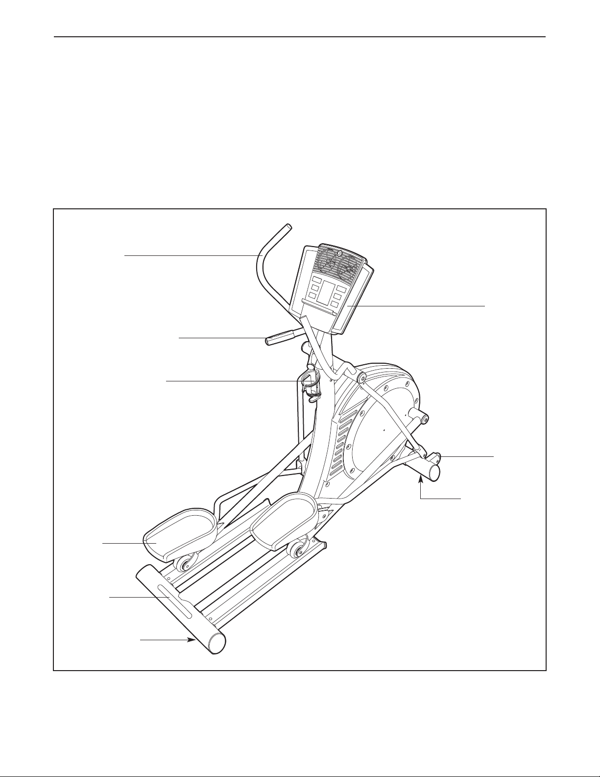
Handlebar
Handgrip Pulse Sensor
®
L
R
ions after reading this manual, please see the front
t
cover of this manual. To help us assist you, note the
product model number and serial number before contacting us. The model number and the location of the
erial number decal are shown on the front cover of
s
this manual.
Before reading further, please familiarize yourself with
the parts that are labeled in the drawing below.
Console
Water Bottle Holder*
Pedal
Handle
Levelling Foot
Wheel
Leveling Foot
*Water bottle is not included
4
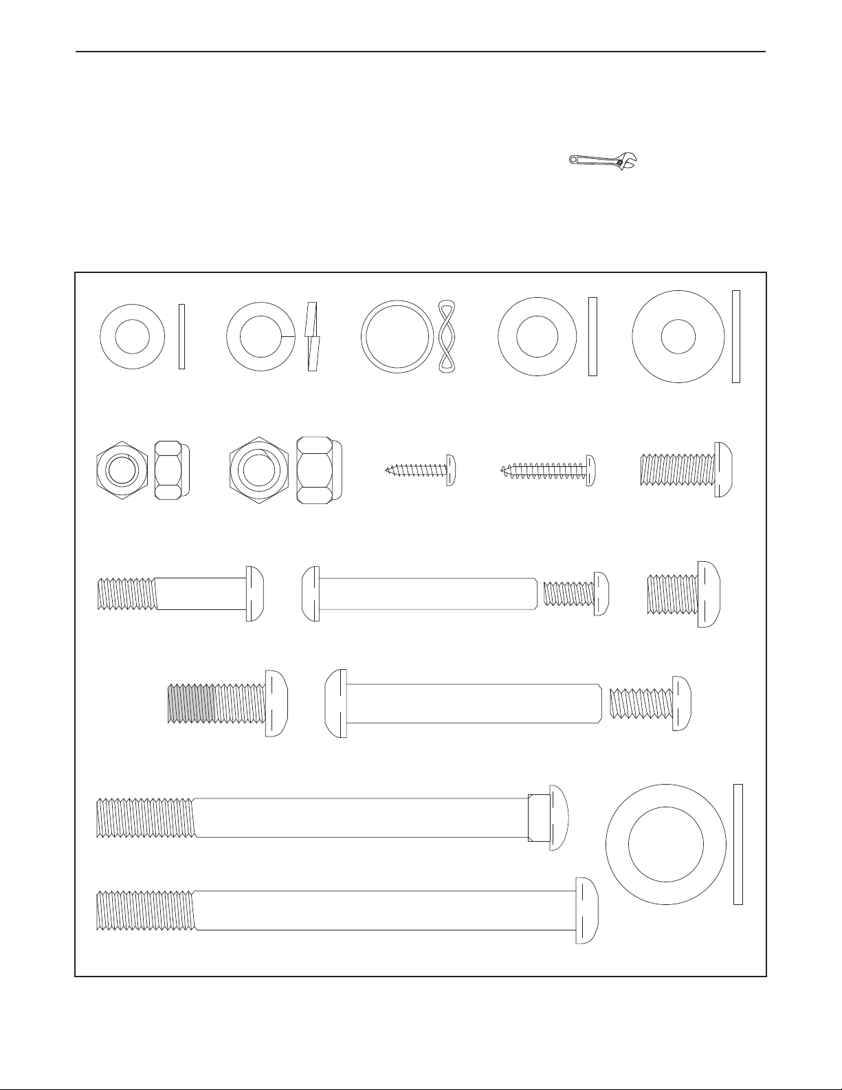
M8 Nylon
Locknut (72)–4
M10 Split
Washer (85)–20
M10 Washer
(67)–14
M8 Small
Washer (18)–4
M8 Washer
(69)–4
M8 x 55mm Bolt
Set (92)–2
M10 x 116mm Carriage Bolt (38)–2
M8 x 38mm Button
Screw (58)–4
Wave Washer
(88)–4
M10 x 123mm Button Screw (87)–2
M10 Nylon
Locknut (70)–2
M4 x 16mm
Screw (47)–4
Thrust Washer
(66)–4
M10 x 13mm Button
Screw (54)–14
M10 x 65mm Bolt
Set (94)–2
M8 x 19mm Button
Screw (56)–4
M10 x 25mm Patch
Screw (48)–4
M4 x 22mm
Screw (57)–2
ASSEMBLY
Assembly requires two persons. Place all parts of the elliptical exerciser in a cleared area and remove the
packing materials. Do not dispose of the packing materials until assembly is completed.
In addition to the included tool(s), assembly requires an adjustable wrench .
As you assemble the elliptical exerciser, use the drawings below to identify small parts. The number in parentheses below each drawing is the key number of the part, from the PART LIST near the end of this manual. The
number following the parentheses is the quantity needed for assembly. Note: Some small parts may have been
preassembled. If a part is not in the hardware kit, check to see if it has been preassembled.
5
1.
To make assembly easier, read the
information on page 5 before you begin as-
embling the elliptical exerciser.
s
Attach the Stabilizer (8) to the Frame (1) with two
10 x 116mm Carriage Bolts (38) and two M10
M
Nylon Locknuts (70).
1
38
8
1
70
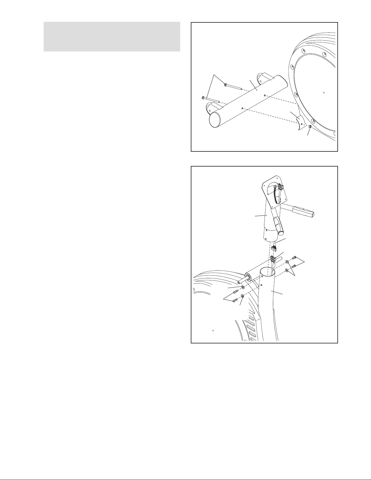
2. Have another person hold the Upright (2) in the position shown. Connect the Upper Wire Harness
(77) to the Lower Wire Harness (78).
Attach the Upright (2) to the Frame (1) with four
M10 x 25mm Patch Screws (48) and four M10 Split
Washers (85). Make sure that no wires are
pinched between the Upright and the Frame.
2
2
77
78
48
85
85
48
85
1
6
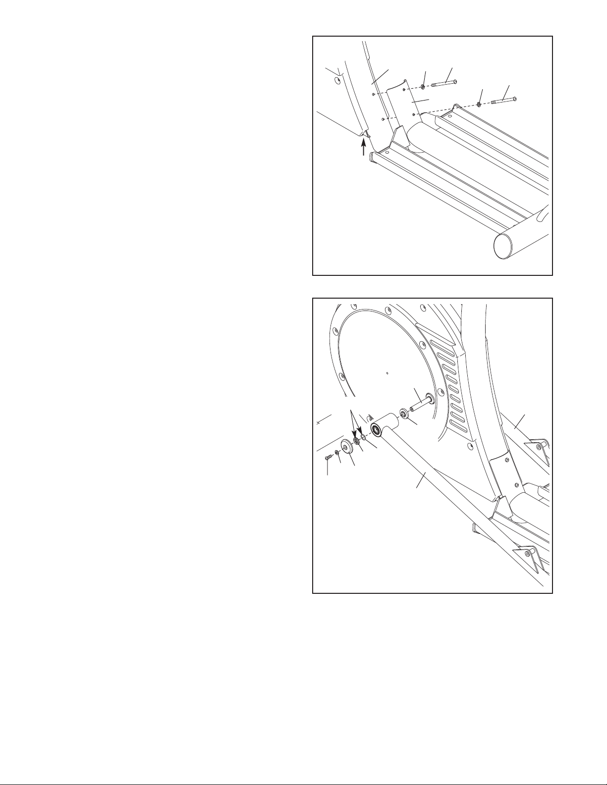
3. Attach the Track Frame (4) to the Frame (1) with
wo M10 x 123mm Button Screws (87) and two
t
M10 Split Washers (85). Finger tighten a Button
Screw into the lower hole first, and then finger
tighten a Button Screw into the upper hole. Then,
tighten both Button Screws. Note: This step may
be easier if you raise the Frame a few inches in the
ocation shown by the arrow at the right while you
l
attach the Track Frame.
3
87
1
85
87
85
4
4. Apply a small amount of the included grease to the
sides of two Wave Washers (88) and two Thrust
Washers (66).
Slide a Weld Spacer (89) onto the Left Crank Arm
(83). Next, identify the Left Track Arm (12), which
is marked with an “L.” Orient the Left Track Arm as
shown, and slide it onto the Left Crank Arm. Then,
slide a Wave Washer (88) on the end of the Left
Crank Arm.
Slide an M8 Small Washer (18) and an Axle Cap
(41) onto an M8 x 19mm Button Screw (56). Next,
slide a Thrust Washer (66) onto the shoulder of
the Axle Cap. Then, tighten the Button Screw into
the end of the Left Crank Arm (83). Make sure
that the Thrust Washer remains on the shoulder of the Axle Cap, and that the Wave Washer
(88) remains on the end of the Left Crank Arm.
Repeat this step to attach the Right Track Arm
(11) to the right side of the elliptical exerciser.
4
56
Grease
18
41
66
83
11
89
88
12
7
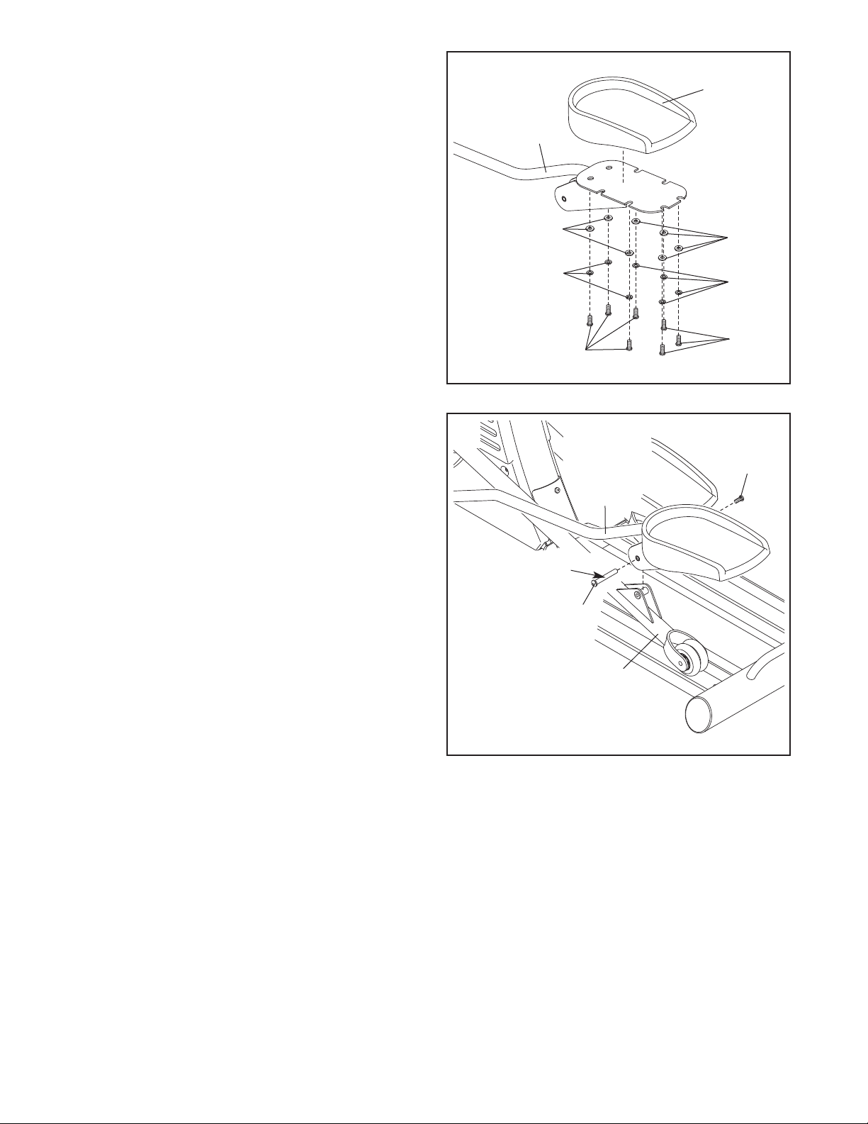
5. Attach a Pedal (21) to the Left Pedal Leg (14) with
even M10 x 13mm Button Screws (54), seven
s
M10 Split Washers (85), and seven M10 Washers
(67).
5
1
2
Attach the other Pedal (not shown) to the Right
Pedal Leg (not shown) in the same way.
6. Apply a thin film of grease to the barrel of an M10
x 65mm Bolt Set (94). Next, fit the bracket on the
Left Pedal Leg (14) onto the bracket on the Left
Track Arm (12). Attach the Left Pedal Leg to the
Left Track Arm with the Bolt Set.
Attach the Right Pedal Leg (not shown) to the
Right Track Arm (not shown) in the same way.
14
67
85
54
6
14
67
85
54
94
Grease
94
12
8
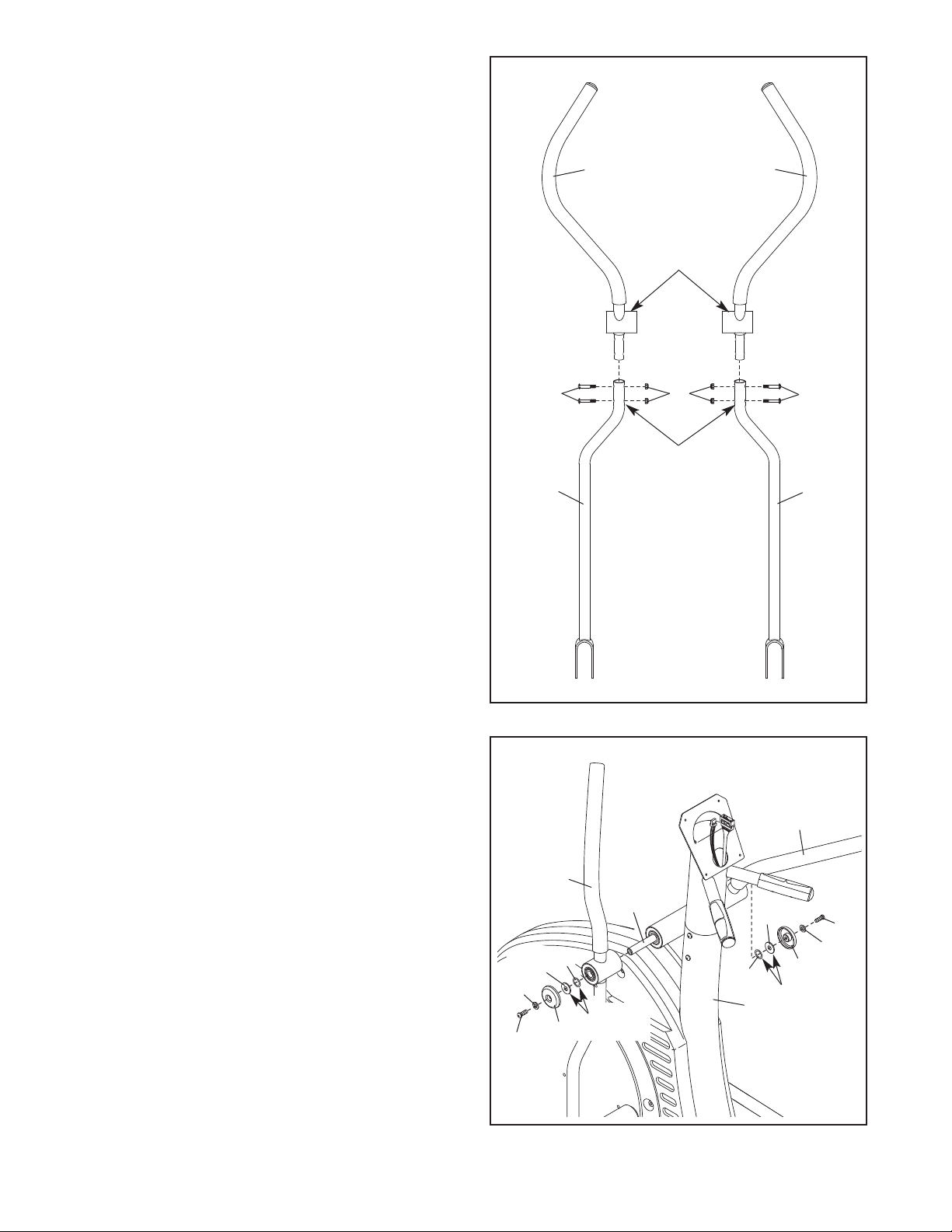
7. Identify the Left Handlebar (19), which is marked
with an “L.” Insert the Left Handlebar into one of
the Handlebar Legs (17). Next, turn the Left
andlebar and the Handlebar Leg so that the
H
wide side of the pivot tube on the Left
andlebar is above the hexagonal holes in the
H
Handlebar Leg. Attach the Left Handlebar with
two M8 x 38mm Button Bolts (58) and two M8
Nylon Locknuts (72). Make sure that the Nylon
Locknuts are inside of the hexagonal holes. Do
not tighten the Button Bolts yet.
Assemble the Right Handlebar (20) and the other
Handlebar Leg (17) in the same way.
7
0
19
Wide side of
pivot tube
2
8. Apply a small amount of grease to the sides of two
Wave Washers (88) and two Thrust Washers (66).
Slide the Left Handlebar (19) onto the Handlebar
Axle (16) as shown. Next, slide a Wave Washer
(88) onto the end of the Handlebar Axle.
58
17
8
72
Hexagonal
Holes
58
17
20
Slide an M8 Small Washer (18) and an Axle Cap
(41) onto an M8 x 19mm Button Screw (56). Next,
slide a Thrust Washer (66) onto the shoulder of
the Axle Cap. Then, tighten the Button Screw a
few turns into the end of the Handlebar Axle (16).
Make sure that the Thrust Washer remains on
the shoulder of the Axle Cap, and that the
Wave Washer (88) remains on the end of the
Handlebar Axle.
Assemble the Right Handlebar (20) in the same
way. Then, tighten both M8 x 19mm Button Screws
(56) at the same time.
19
18
56
66
88
41
16
Grease
88
1
66
56
18
41
Grease
9
 Loading...