

Page 1
Slick Assembly Manual
Slick Assembly Manual
Page 2

Thank you for purchasing the RedWing RC Slick. We have provided you with the highest quality kit and
flight performance possible. We wish you great success in the assembly and flying of your new
RedWing RC Slick.
Caution!
1. You should not regard this airplane as a toy.
2. To ensure safety, please read this instruction manual thoroughly before assembly.
3. Building and operating a model airplane requires diligent practice and correct guidance. An
inexperienced flyer can cause serious injury and property damage.
4. Seek the assistance of an experienced RC pilot or model airplane club for help with assembly,
operation and maintenance to assure your flying experience is both enjoyable and safe.
5. Fly only in AMA (Academy of Model Aeronautics) approved areas.
Redwing RC warrants this model to be free from defects in both materials and workmanship from date
of purchase. This warranty does not cover any component parts damaged by use or modification. In
no case shall RedWing RC’s liability exceed the original cost of the purchased kit. Further, RedWing RC
reserves the right to change or modify this warranty without notice.
In that RedWing RC has no control over final assembly or materials used for final assembly, no liability
shall be assumed nor accepted for any damage resulting from the use by the user of the final userassembled product. By the act of using the user-assembled product, the user accepts all resulting
liability.
We, as the kit manufacturer, have provided you with a top quality, thoroughly tested kit and
instructions, but ultimately the quality and fly ability of your finished model depends on how you built
it; therefore, we cannot in any way guarantee the performance of your completed model, and no
representations are expressed or implied as to the performance or safety of your completed model.
Page 3

Specifications
Wingspan: 87”
Wing area: 1440 in²
All up flying weight: 15 to 17 pounds, depending on hardware and building style
Overall length: 83”
Engine: any 50 to 60cc engine (DLE 55, DLE 55RA, DLA 58 recommended)
Radio: 6 channel recommended (4 channel possible)
CG: 25 to 30% back from LE at root
Servos: 200 in-oz torque, metal gear. Digital servos are recommended.
Assembly
Prior to assembly, inspect entire framework. Pay particular attention to covering and seams in
covering. Temperature extremes in shipping containers sometimes cause wrinkles or loose seams to
form. Most wrinkles and loose seams can easily be fixed by taking a little time with a sealing iron or
heat gun. Persistent wrinkles are generally caused by air trapped under the covering. These can be
removed by puncturing the covering with a pin to create and escape for the air. Vibrations during
shipping can loosen glue joints. These can be repaired with CA glue.
Notes on Assembly
Assembly order is non-critical. Many steps can be done whenever the builder wants to do them. For
instance, hinging of all surfaces can be done at the same time. Same goes for control horns. They can
all be done at the same time. Installation process for both hinges and control horns will be described
once. The order described in this manual is intended to minimize the time it takes to assemble this kit.
It is recommended that the landing gear be installed early to keep the fuselage from rolling. Wheels
and pants can be installed at any time. Some builders may prefer to install the wheels and pants last,
just to keep the airplane from rolling off their work bench.
Page 4

Hardware required to finish the kit
50 cc class engine with muffler (DLE-55, DLE-55RA or DLA-58 recommended)
Standoffs for engine (normally included with engine)
Propeller: 23”x8” or 24”x8” (suitable size for engine used)
Spinner: 3-3/4”
Servos:
5 for flight surfaces (XQ 4020 available from RedWing RC)
1 for throttle (metal gear recommended)
Receiver: 4 channel minimum. 6 channel or more recommended
Transmitter: 4 channel minimum. 6 channel or more computerized recommended
Optical kill switch on ignition recommended (available from RedWing RC)
Battery:
3000 mah LiFe can be used for both ignition and receiver (available from RedWing RC)
If desired, a separate battery of at least 1000 mah capacity can be used for ignition.
Switch: 2 HD switches (available from RedWing RC)
Servo extensions:
Aileron: two 12” heavy duty and two 6” (available from RedWing RC)
Elevator: two 36” heavy duty (available from RedWing RC)
Throttle: 12” heavy duty (available from RedWing RC)
Servo safety clips for each extension (available from RedWing RC)
Tools, etc. required to finish model
Screwdrivers: Phillips and common
Wrenches: metric open end or box
Ball drivers or allen head wrenches
Drill with assorted bits
Pliers or crimping tool
Hobby heat gun and hobby sealing iron
Modeling knife (X-acto with #11 blade, or equivalent)
Wire cutters
Pen or marker (Sharpie, or equivalent)
Scissors
Thin, medium CA and CA accelerator
15-30 minute epoxy with mixing cups and mixing sticks
Gorilla Glue or Tightbond II for hinges (if don’t want to use epoxy)
Blue threadlock
Rubbing alcohol and wipes or paper towels (denatured alcohol may affect painted surfaces)
Q-tips are handy, but not a necessity
Hemostat or small needle nosed pliers
Page 5

Notes on radio installation
While this airplane can be flown with a simple 4 channel transmitter, it is recommended that at least 6
channel computerized transmitter be used. The 4 channel transmitter would require the use of Yharnesses on both aileron and elevator servos. The 6 channel transmitter allows plugging each servo
into its own channel. Servo sub trim and end points can then be adjusted to optimize the servo control
horn configuration.
At neutral, aileron servo arms should be parallel with the aileron hinge line. Elevator servo arms
should be vertical.
Turnbuckle type pushrods are included for the ailerons and elevators. Turnbuckles have a left hand
thread on one end and a right hand thread on the other. They are convenient as they allow finer
adjustments than a conventional clevis. They also allow adjustment without disconnecting anything.
However, initially they are easier to set up if you center the servo arm, center the control surface and
hold the turnbuckle up to both ball links to see how far to thread the turnbuckle in. Thread the
turnbuckle this amount into each ball link. This will have the pushrod length close to what is needed.
It can be further adjusted after installing the servo arm on the servo.
Make a point to install the turnbuckles in the same direction on all control surfaces. For instance, use
the right hand thread at the servo and left hand thread at the control horn. If they are all installed the
same way, then rotating the turnbuckle clockwise or counter clockwise has the same effect on all
control surfaces. For instance, turning clockwise shortens the pushrod and pulls the control surface
down.
Recommended control setup has control surface ball links installed on the outer hole of the control
horns and the other ball link attached at the second from the outer hole on the servo arm. Adjust
servo end point on the transmitter to give desired control throw. Rudder ball links should be installed
using the outer holes on the servo arm.
Make sure elevator halves center to the same place. This is done by positioning the servo arms so they
are both vertical when the elevator stick is neutral. Adjust the length of the turnbuckle pushrods for
neutral elevator. Maximum throw in both directions is set with servo end point on the transmitter.
Select an inner hole on the throttle servo arm that requires servo throw of greater than 100% in both
low and high throttle directions. The model assembled for this manual has a 1” throttle arm on the
carburetor and the pushrod is ¾” from the center of the servo spline. This requires about 115% throw
in both high and low directions to achieve full throttle throw.
Page 6
+-
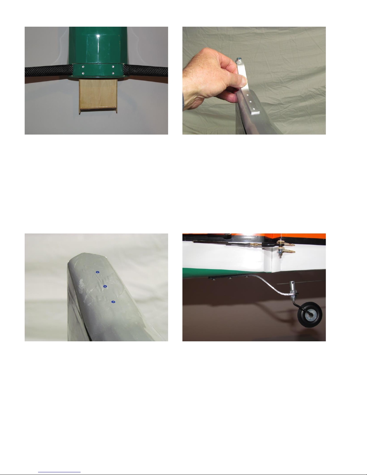
Main gear is installed using nuts and bolts that are
inserted in predrilled holes. Bolts go through landing
gear cover, main gear, then fuselage bottom. Nuts
are installed inside the fuselage and accessible via the
canister tunnel. Note: remove covering from landing
gear cover at four bolt positions.
Place tail wheel bracket in positions and mark
location of the mounting holes
Drill holes for mounting screws.
Install tail wheel bracket only. Note: wheel and
steering linkage can be installed later.
Page 7
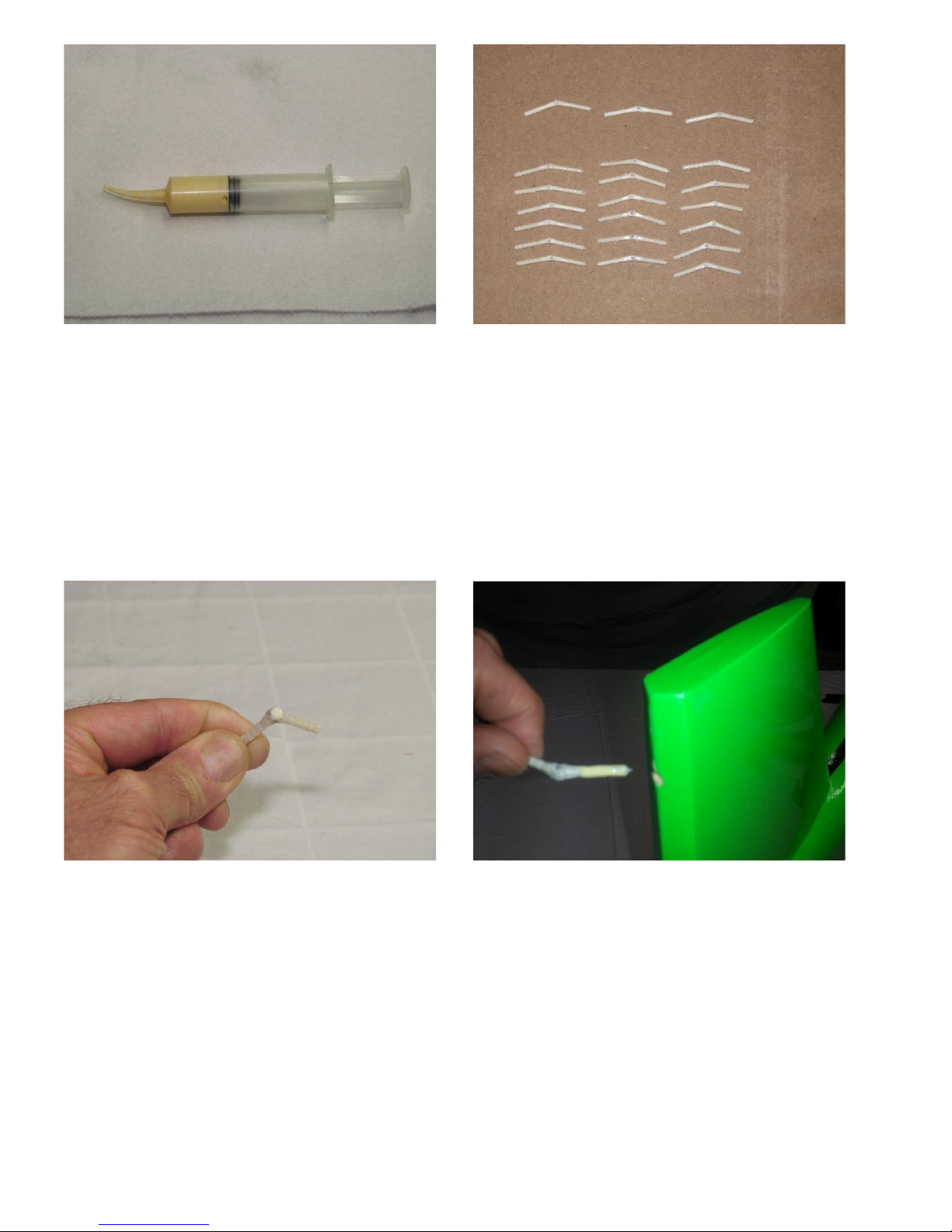
Several different types of adhesive are acceptable
for installing hinges. Epoxy, Gorilla Glue and
aliphatic resin (Titebond II) all work. One
benefit of the aliphatic resin is it cleans up with
water until it cures. A dental syringe is an
excellent tool for injecting glue into the holes.
Remove all hinges from their pre-drilled holes.
Scuff barbs on all hinges with coarse sandpaper
or similar tool. Note: two hinges have had one
barb clipped off. The short side of these two
hinges go into the stabilizer in the hole closest to
the fuselage.
Place a small amount of lubricant on the pin of
the hinge and flex the hinge back and forth to
coat the pin with lubricant. Lithium grease was
used in this model.
You can use the same Lithium grease to keep
your door hinges from squeaking.
Inject a small amount of adhesive into the hole in
the flying surface. Also add some adhesive to the
barbs of the hinge. Insert the hinge into the hole
until the pin is at the hinge line.
Page 8
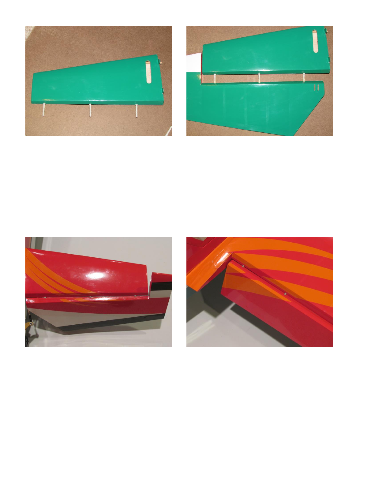
Install all hinges in the flying surface. Make sure
all hinges line up the same. If you would like,
proceed directly to installing the hinges in the
control surface at this time.
Inject adhesive into all holes and onto the barbs
of all hinges. Make sure all hinges will go in
holes. Push elevator into position. Once hinges
are properly seated, rock elevator back and forth
a few times to help align hinges.
Once all hinges have been installed, clean off
excess adhesive. Note: minimal hinge gap and
bevel to bevel throw. If necessary, increase hinge
gap slightly to achieve desired control throw.
Repeat process for aileron and rudder hinges.
Note: minimal hinge gap and bevel to bevel
throw.
Page 9
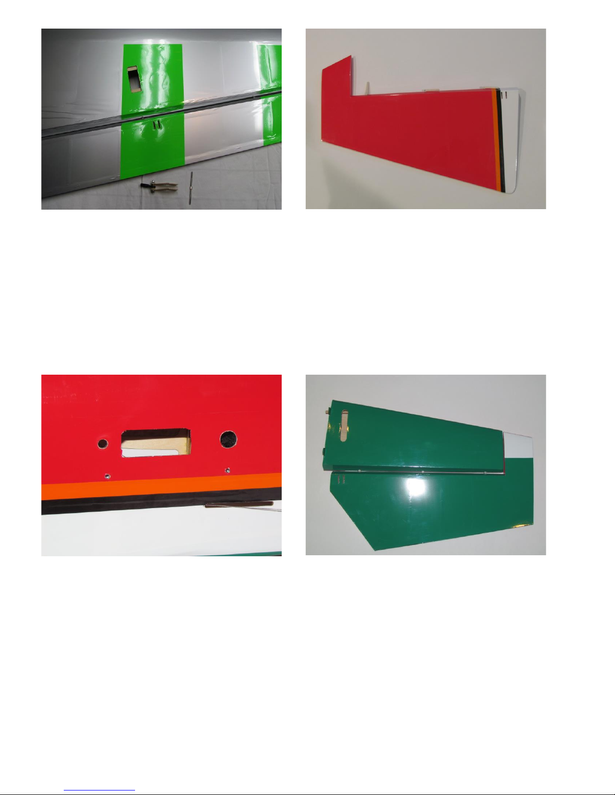
Remove covering over aileron servo openings and
control horn slots. Covering can be removed by
either cutting it off with an X-acto or similar knife or
by melting it with a pencil type of soldering iron. The
soldering pencil seals the covering to the structure,
but leaves some excess that needs to be cut off.
Note slots for rudder horns near bottom of rudder.
Openings in fuselage for horizontal stabilizer
mounting, elevator servo lead and rudder pull-pull
cable exit.
Slot opened in horizontal stabilizer for the elevator
servo arm and elevator slots for control horns.
Page 10
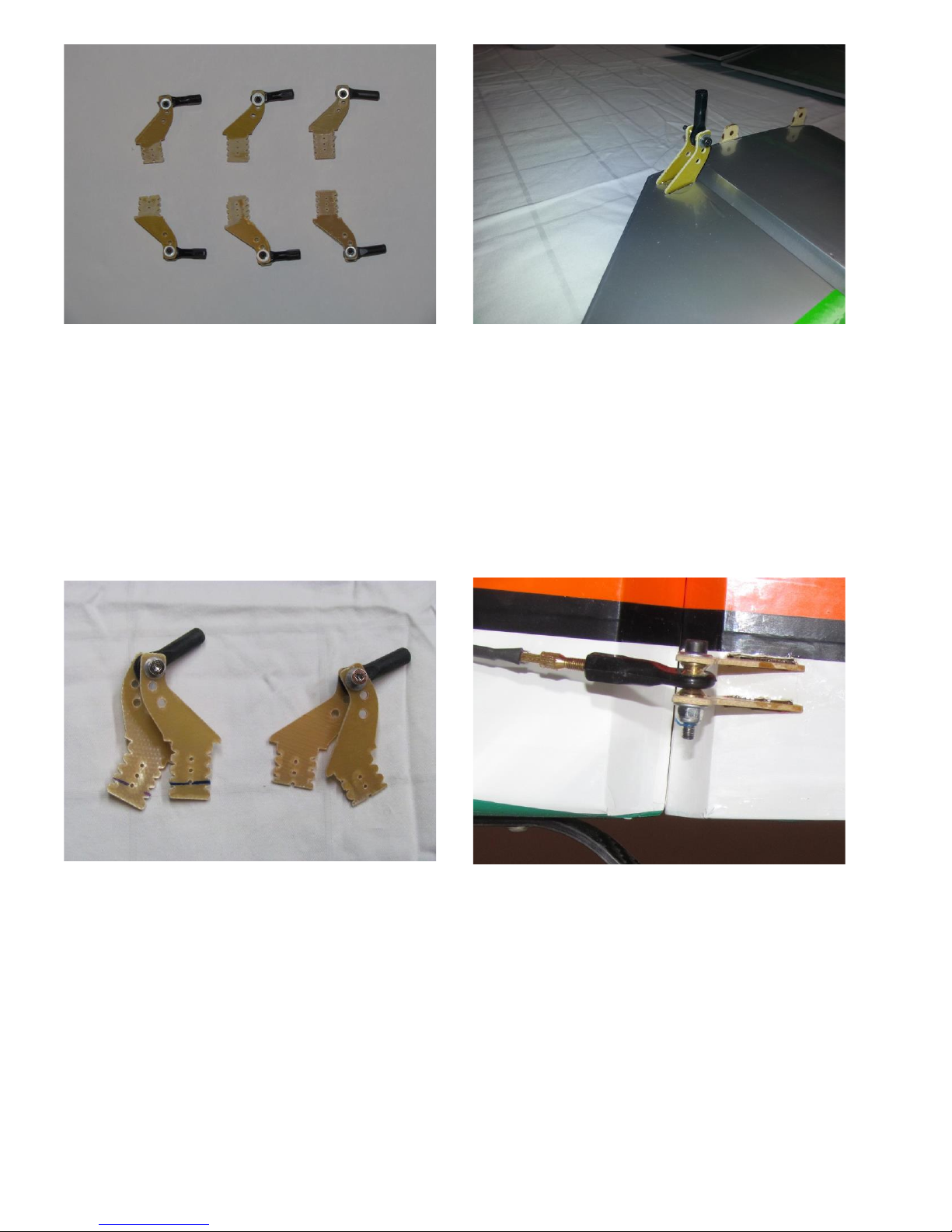
Assemble control horns assemblies and tighten bolt.
Scuff bottom of control horns (glue area) with coarse
sandpaper for better adhesion. Inject epoxy into
both control horn slots. Apply additional epoxy to
both sides of each control horn. Insert control horns
into slots and clean up excess epoxy that oozes out of
slots. Rudder horns need to be trimmed to fit.
Elevator control horns have been installed. Note:
excess epoxy has not been cleaned off yet.
Rudder uses two pairs of control horns for pull-pull
cables. The horns install directly opposed from each
other, thus will not fit unless trimmed. The horns on
the left have been marked. The horns on the right
have been trimmed. Verify both sets of horns fit
prior to gluing in place.
Install both pairs of rudder control horns with epoxy.
Pull-pull cable will be installed later.
Page 11
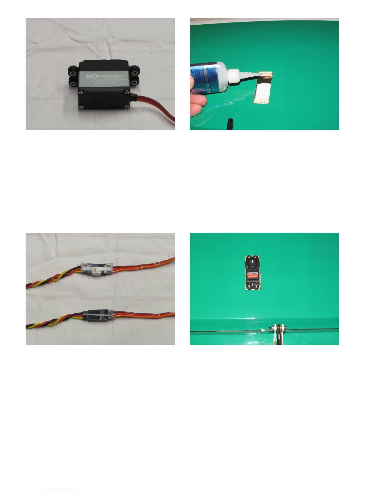
Verify control horns have cured prior to installing
servos.
Install isolation grommets and brass bushings in all
servos. Note: brass bushings are installed from the
bottom.
Set aileron servo in position. Drill all four holes for
mounting screws. Install screws, then remove and
move servo out of the way. Place a drop of thin CA
glue in each hole to toughen threads in the plywood.
Reinstall aileron servos. Use 18” (or 12” with 6” at
receiver) extension on servo lead. Don’t forget to use
some sort of restraint on the connector. Restraints
are commercially available. Dental floss can be
wrapped around the connector and tied 3 or 4 times.
Some people like heat shrink tubing. If heat shrink is
used, avoid overheating the connector.
Install aileron servo. Note: servo spline is closer to
the leading edge of the wing.
Page 12
Remove covering over aileron servo openings and
control horn slots. Covering can be removed by
either cutting it off with an X-acto or similar knife or
by melting it with a pencil type of soldering iron. The
soldering pencil seals the covering to the structure,
but leaves some excess that needs to be cut off.
Openings in fuselage for elevator mounting, elevator
servo and rudder pull-pull cable exit.
Slots for elevator control horns have been marked,
but not cut yet.
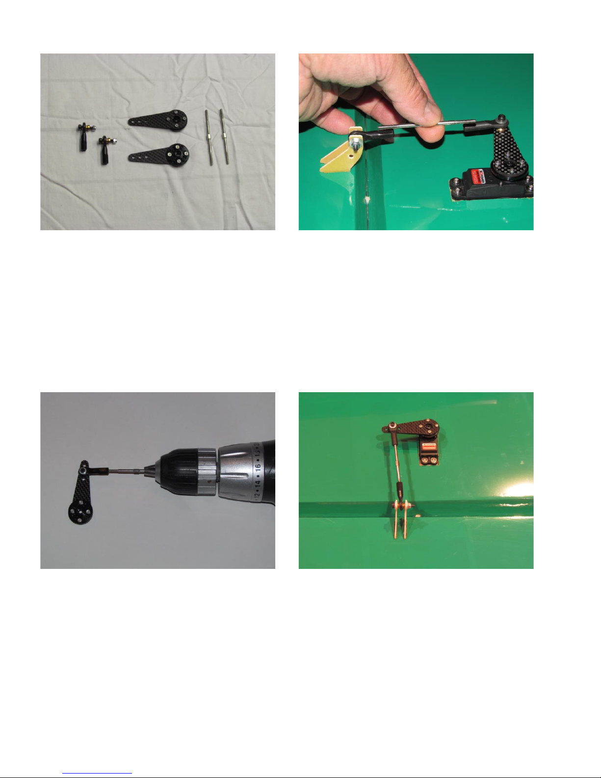
Prepare servo arms. Carbon fiber arms are provided
for all control surface servos. The round wheels that
come with the servos can be used. If desired,
aluminum wheels can be purchased from RedWing
RC for an additional cost. These wheels are drilled
and tapped to fit the arms.
Ball links can be pre-threaded with the help of a
variable speed drill. Chuck the turnbuckle pushrod
into the drill and thread into the ball link. Just be
sure to use a slow speed when threading the ball link.
Pre-thread both ball links. Leave the turnbuckle on
the second ball link. Manually thread the turnbuckle
back onto the first ball link.
Completed aileron servo/turnbuckle installation.
Servo arm is parallel to hinge line when aileron is
neutral.
Set control surface at neutral. Center servo.
Hold turnbuckle up to ball links to get an idea of
how far to thread the turnbuckle into the ball
links.
Page 13
Remove covering over aileron servo openings and
control horn slots. Covering can be removed by
either cutting it off with an X-acto or similar knife or
by melting it with a pencil type of soldering iron. The
soldering pencil seals the covering to the structure,
but leaves some excess that needs to be cut off.
Note slots for rudder horns near bottom of rudder.
Openings in fuselage for elevator mounting, elevator
servo and rudder pull-pull cable exit.
Slots for elevator control horns have been marked,
but not cut yet.
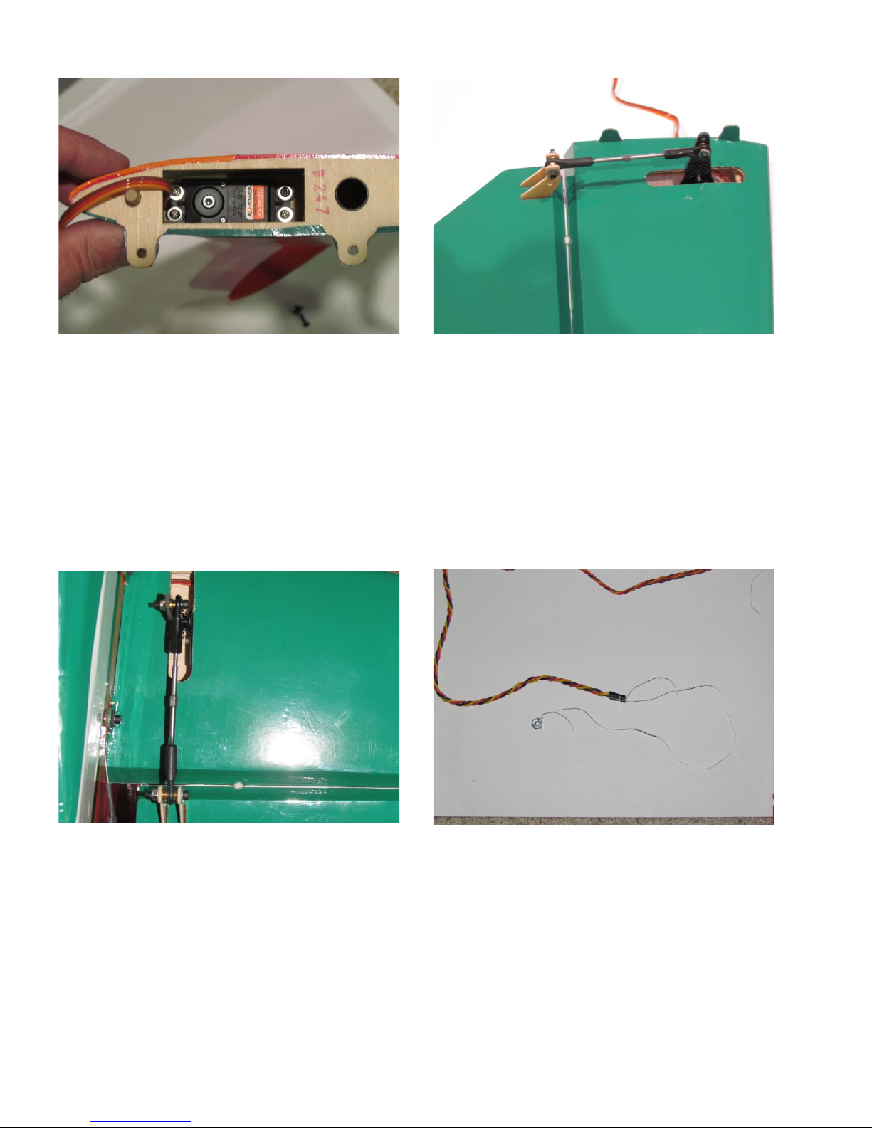
Install elevator servo inside the horizontal stabilizer
with output spline facing the leading edge. An easy
way to hold the servo screws is to use a hemostat
inserted through the servo arm slot.
Install elevator servo arm and turnbuckle pushrod.
Ball link is bolted on the servo side of the servo arm
(away from the fuselage). This gives the straightest
linkage and improves the mechanical advantage over
mounting the ball link on the other side of the servo
arm.
A nut tied to a string can be used to help pull the
elevator servo extensions the length of the fuselage.
Page 14
Remove covering over aileron servo openings and
control horn slots. Covering can be removed by
either cutting it off with an X-acto or similar knife or
by melting it with a pencil type of soldering iron. The
soldering pencil seals the covering to the structure,
but leaves some excess that needs to be cut off.
Note slots for rudder horns near bottom of rudder.
Openings in fuselage for elevator mounting, elevator
servo and rudder pull-pull cable exit.
Slots for elevator control horns have been marked,
but not cut yet.
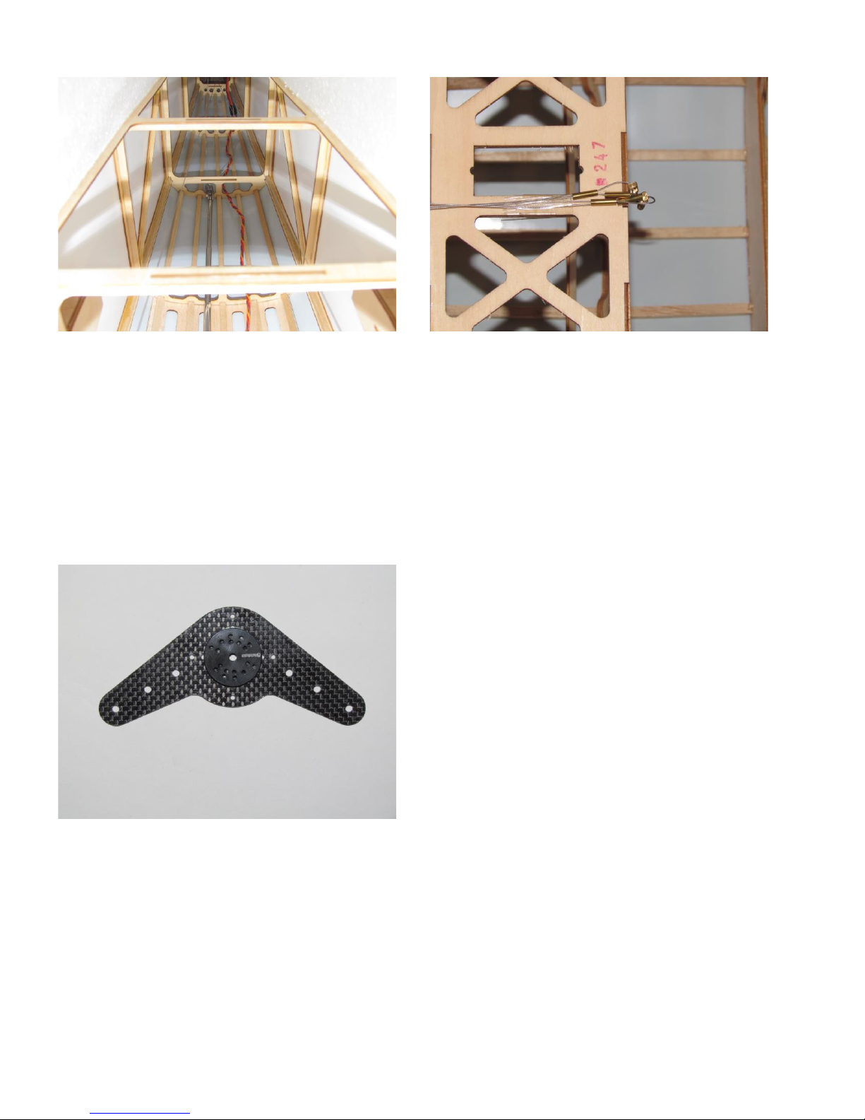
A magnet on an extendible wand makes pulling the
elevator servo extension much easier. Magnet
attracts the nut on the string. Collapse the wand as
the extension is pulled through the fuselage.
Alternately, stand the fuselage on the firewall and
shake gently while feeding the extension.
Rudder pull-pull cables have been run, but crimps are
not installed. If using heat shrink tubing over crimp
and end of wire, be sure to slide it over the wire prior
to installing the crimps. The shrink tubing provided in
the kit does not fit over the threaded connector.
Mounting holes in the carbon fiber arm do not line up
with the aluminum wheel and must be drilled. Use a
small drill bit and drill through the desired holes in
the wheel. Once all holes are drilled, remove the
aluminum wheel and redrill the holes in the CF arm
with the proper size. Bolt aluminum wheel to CF
servo arm.
Page 15
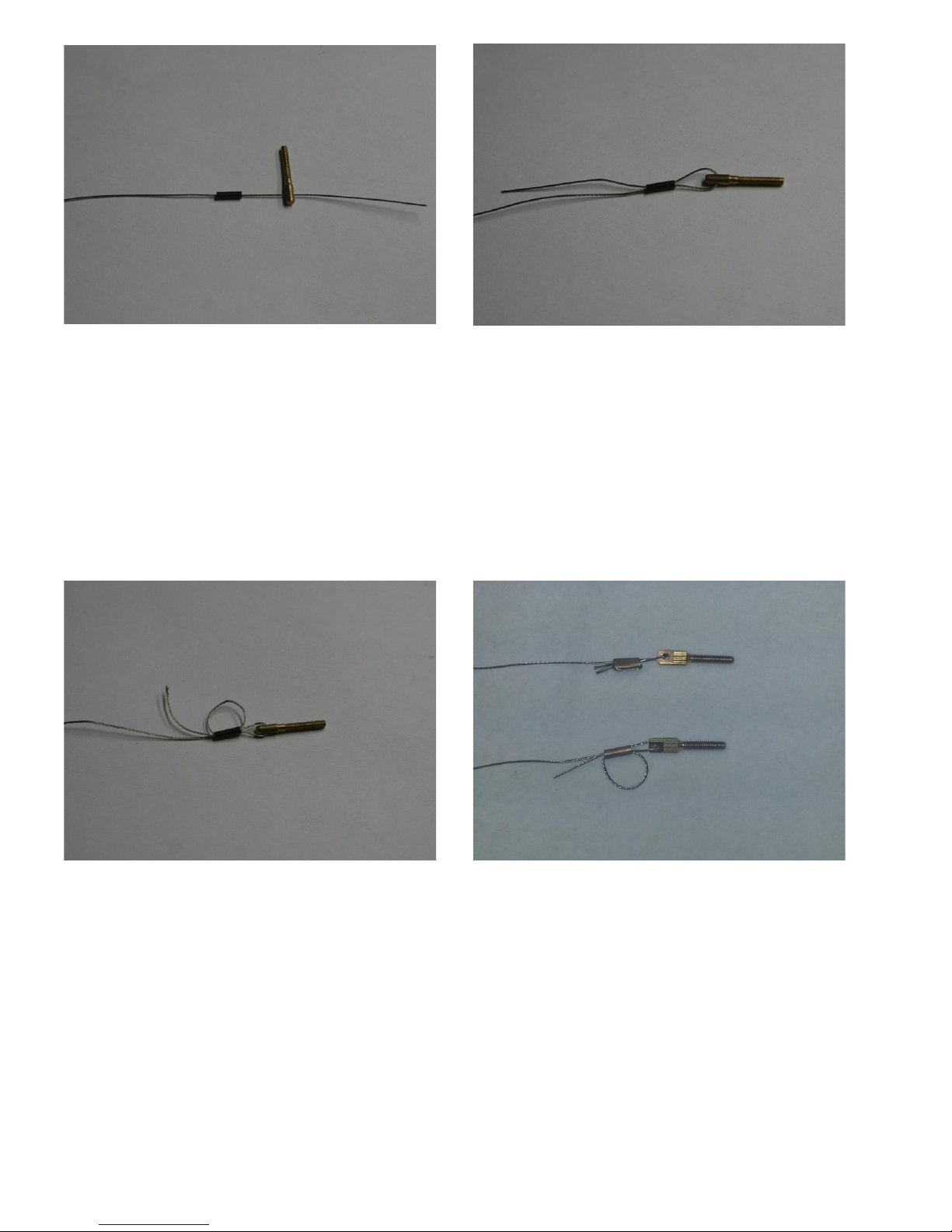
Insert cable through crimp, then to threaded
connector.
Double cable back through crimp.
Loop cable back through crimp. Pull end to
shorten loop prior to crimping.
Crimp with either pliers or a crimping tool. Add
a drop of CA after crimping. Assemble both
rudder cables to the length determined earlier.
Once crimped, slide shrink tubing up over end of
wire and the crimp. Heat tubing to shrink.
Page 16
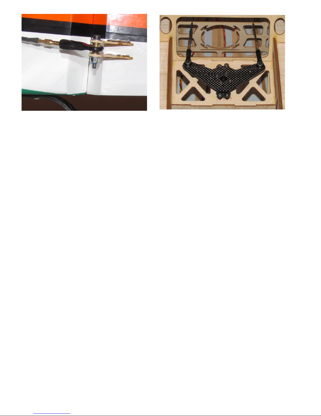
Thread one end of cable onto ball link on rudder
horn. Feed cable through fuselage to rudder
servo arm.
Remove ball link from servo arm. Thread cable
end onto ball link. Reattach ball link to servo
arm. Install second cable, making sure to cross
the cables. Note: getting cables tight enough and
centering rudder is a trial and error process.
Cables need to be snug, but not “guitar string”
tight.
Page 17
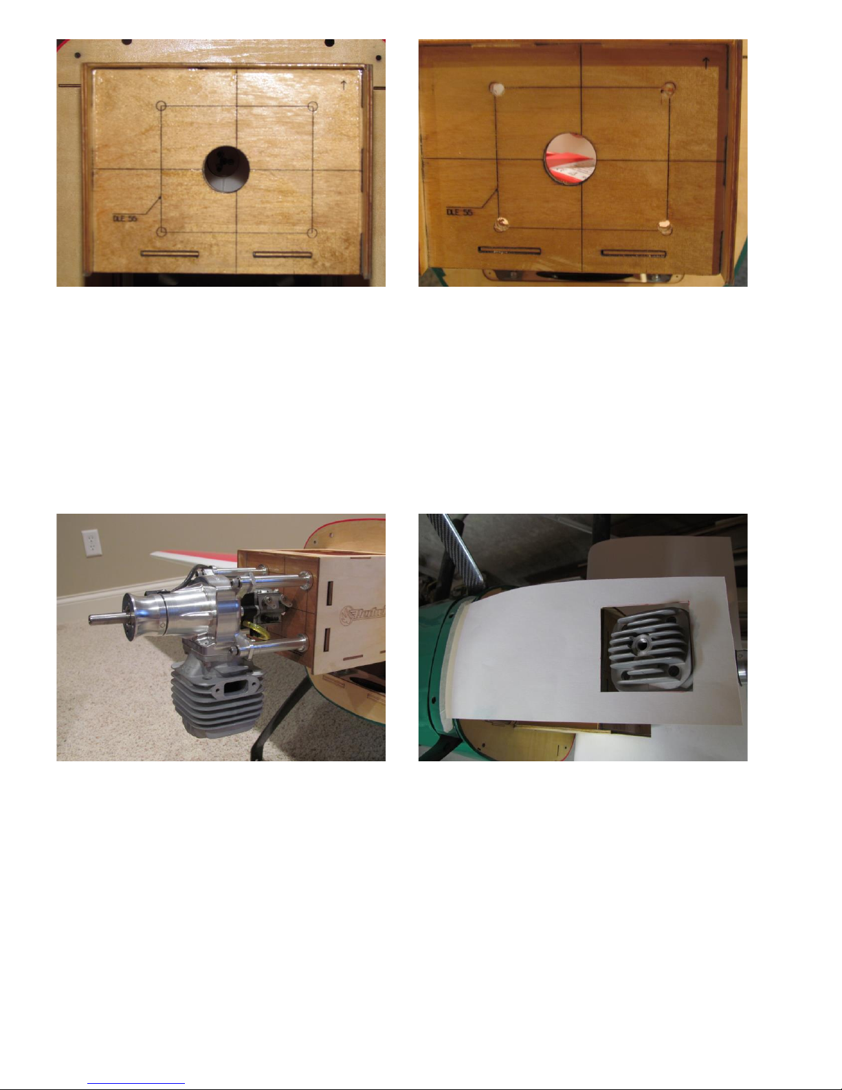
Let’s move on to the fuselage. Firewall is laser
etched for DLE-55 mounting bolts.
A DLA-58 is being installed on this Slick. The
bolt pattern is slightly different than the DLE-55.
Mounting holes were adjusted and drilled
accordingly.
Install standoffs but don’t use thread lock on bolts
yet. Note: a 10 mm open end wrench fits on the
flats of the standoffs.
Temporarily mount engine.
Make a template of the engine head using poster
board (or something similar). Tape to fuselage
near landing gear. The tape will act as a hinge.
Page 18
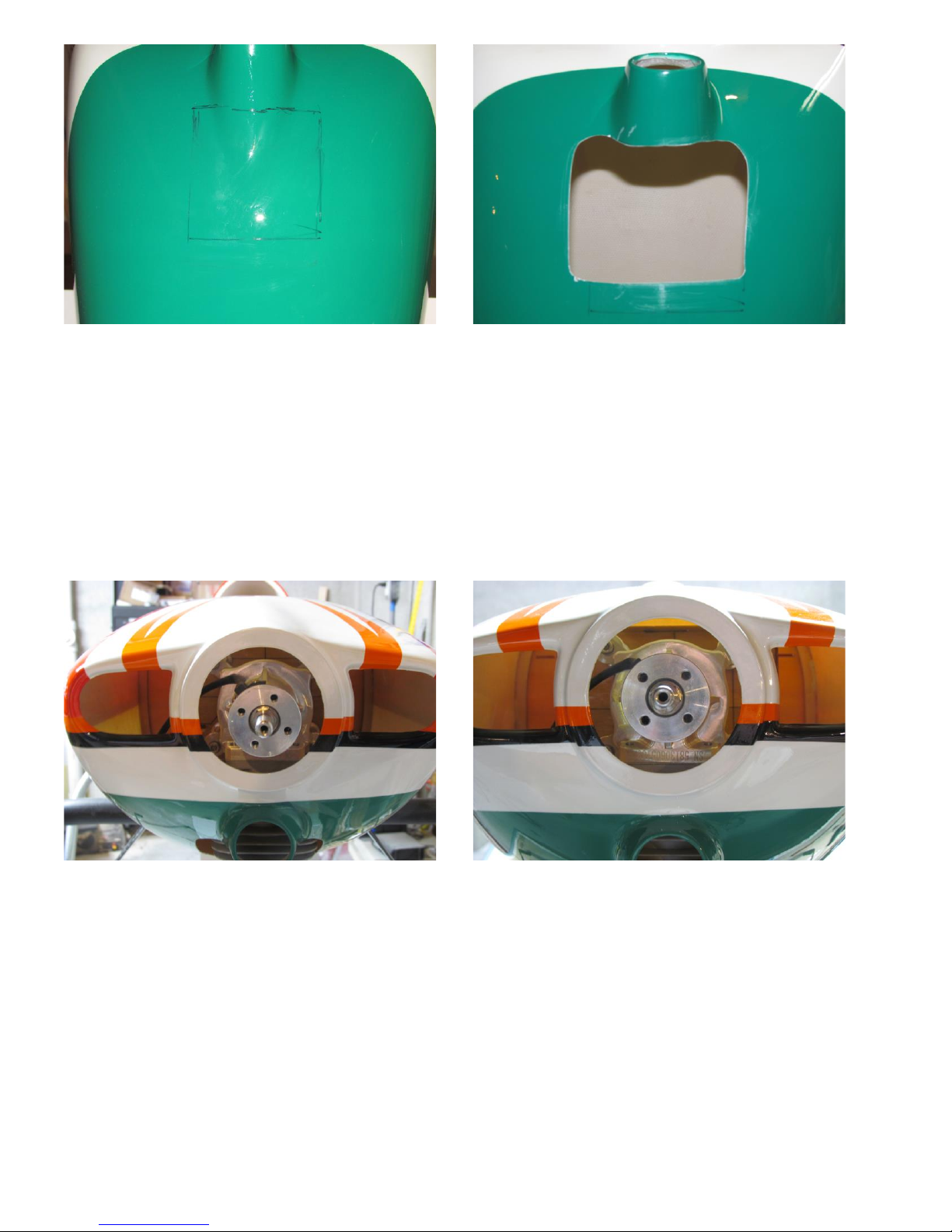
Remove engine and install cowl. Fold template
back onto the cowl. Trace outline of engine head
onto cowl using Sharpie or similar marker. Fold
template back and remove cowl.
Make initial cut somewhat smaller than the
template shows. The cowl has a pretty steep
slope at the engine head location. This opening
doesn’t have to be as long as the engine head.
Trial fit the cowl over the engine. There should
be about 1/8” clearance along both sides and the
front of the engine head.
Check to see how the engine fits the cowl. There
must be a difference in centerline between the
DLE and DLA engines. Cowl will not line up
properly with spinner backplate.
Mounting holes were revised to center the engine
within the cowl opening. It looks OK now.
Remove cowl. While engine is still mounted,
remove standoff bolts (from firewall) one at a
time and add threadlock. Reinstall all four
standoff bolts.
Page 19
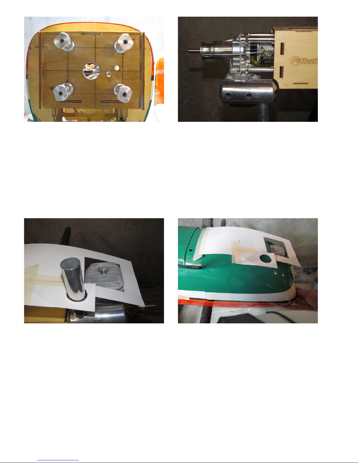
Mark location of throttle pushrod and fuel line.
Remove engine (leave standoffs in place) and
drill both holes. Reinstall engine.
Temporarily mount muffler. In the case of a
DLA-58 the muffler interferes slightly with the
side of the motor box. A notch had to be cut off.
The firewall is completely behind this notch, so
the cut is cosmetic only and won’t affect strength.
Put head template back on. Add a section to
template for the muffler. Carefully remove
muffler.
Reinstall cowl. Transfer position of the muffler
stack to the cowl. Note: the cutout for the engine
head goes just past the spark plug.
Page 20
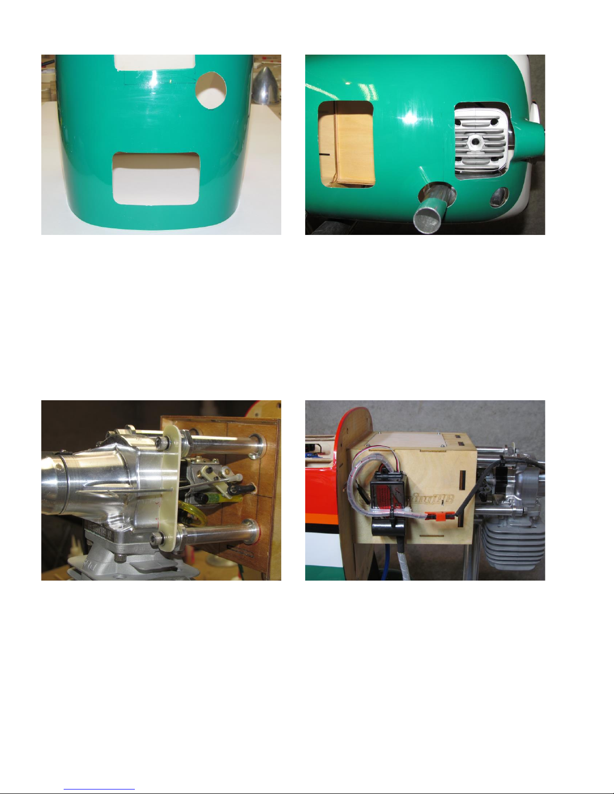
Cut the opening for the muffler stack. While you
are at it, cut the exhaust opening.
Reinstall muffler using the gasket and threadlock.
Install cowl. It may be necessary to enlarge the
muffler stack opening for additional clearance to
install cowl. There may also be an interference
with the front of the muffler like there is in the
case of the DLA-58.
Reinstall engine. This time use threadlock on all
bolts. A G10 plate was used as a choke guide.
DLA didn’t include a longer throttle arm, so one
was made out of G10. A ball link is bolted to the
throttle arm. A snap on ball connector was used
on the choke linkage to give clearance over the
throttle linkage.
Ignition will be held on using Velcro and a zip tie
(not included with kit). Cut holes through side of
motorbox for zip tie. Note: if the ignition is
installed to far forward on the motorbox, it will
interfere with installing the cowl.
Add spiral wrap to power lead, halls sensor lead
and spark plug wire.
Page 21
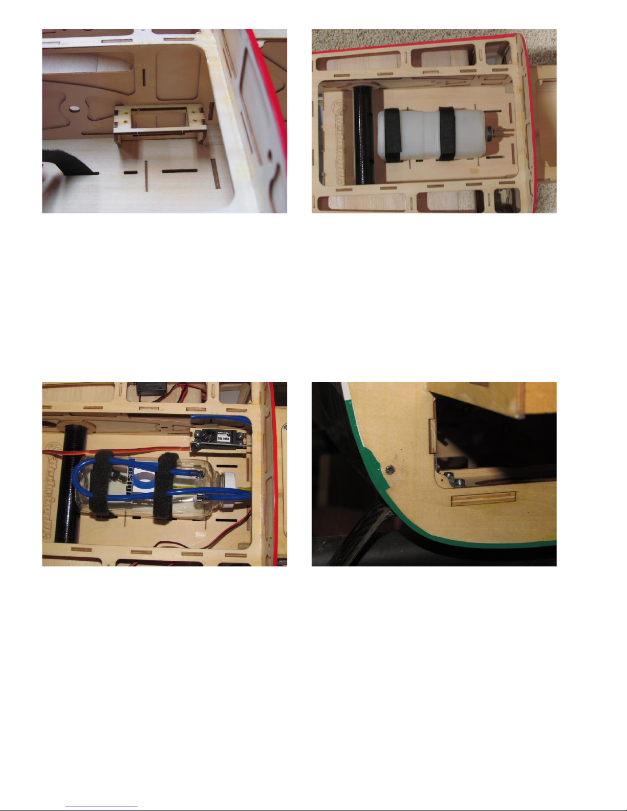
Predrill servo mounting holes in throttle servo
mount. Add a drop of thin CA to each hole.
Glue servo mount into place.
A 550 cc 3 line tank comes preassembled and
installed. We opted to use a 16 ounce tank from
Fortitude.
Tank is strapped in with Velcro. Vent line loops
back over the end of the tank prior to exiting out
the motorbox bottom.
This is a 3 line tank. The other lines go to the
carburetor and fuel dot for filling and emptying
tank.
Note: throttle servo and pushrod have been
installed.
Reinstall cowl. Upper bolts are accessed from
the canopy side. Bottom bolts are accessed from
inside cowl and are difficult to install. Exhaust
opening can be used to access bolts.
Bottom nuts and bolts can be replaced with rare
earth magnets. Use one magnet on cowl ring, one
on the fuselage. Remember to arrange magnets
to attract, not repel. We also put a bolt at the
bottom center of the cowl ring.
Page 22
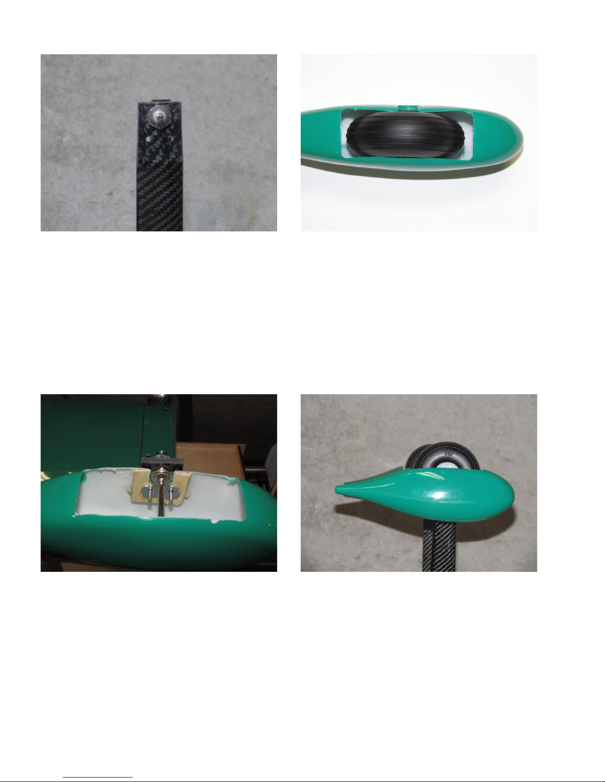
Install axles on main landing gear. Note: the
wheel pants have a tight fit on the axles. The
axles need to be oriented so flat sides are vertical
(points are up and down).
Wheel pants have a very tight fit with wheels.
The wheel pants have to be opened up to fit the
wheels properly.
Install wheel pants. Place a drop of medium CA
under each blind nut as the bolt is being
tightened. Axles need to be shortened about ¼”
to fit in the wheel pants. File flat spots on axle at
wheel collar locations. Mounting bolts are too
long and need to be shortened to avoid hitting the
wheels. Install wheels and wheel collars.
Wheels and wheel pants installed. Note: when
properly aligned, the front pant hides the back
one.
Page 23
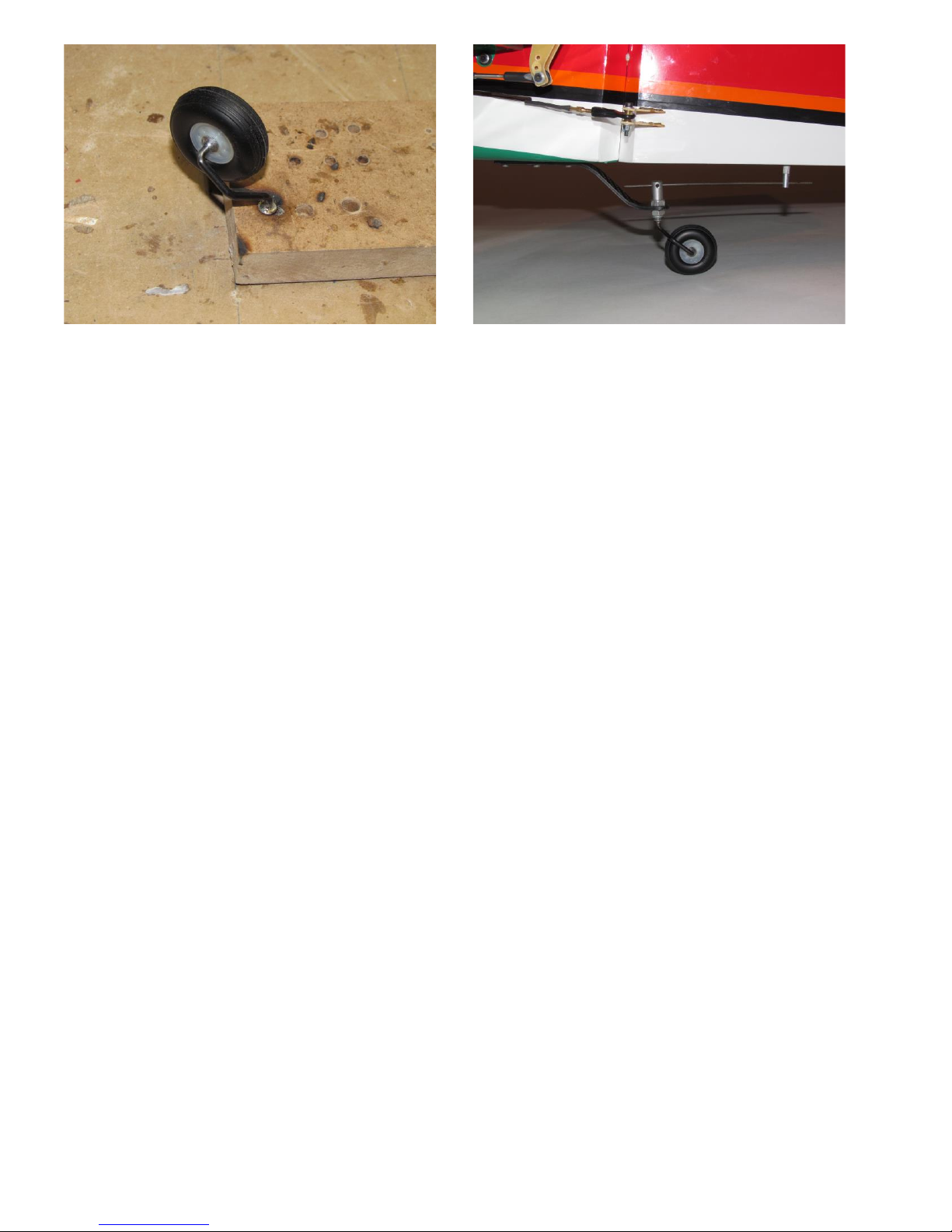
Only one wheel collar is given in the kit for the
tail wheel. A washer was soldered onto the axle
to center the wheel. A second washer was
soldered as a stop to keep the axle from riding up
the tail wheel bracket too far. File a flat spot for
the wheel collar.
Install the tail wheel assembly onto the CF tail
wheel bracket. Drill a hole in the bottom of the
rudder for the alignment pin and epoxy pin in
place. Leave at least ½” of the tiller wire sticking
out beyond the alignment pin. This will prevent
the tiller wire from coming out of the pin with
high rudder throw.
Page 24
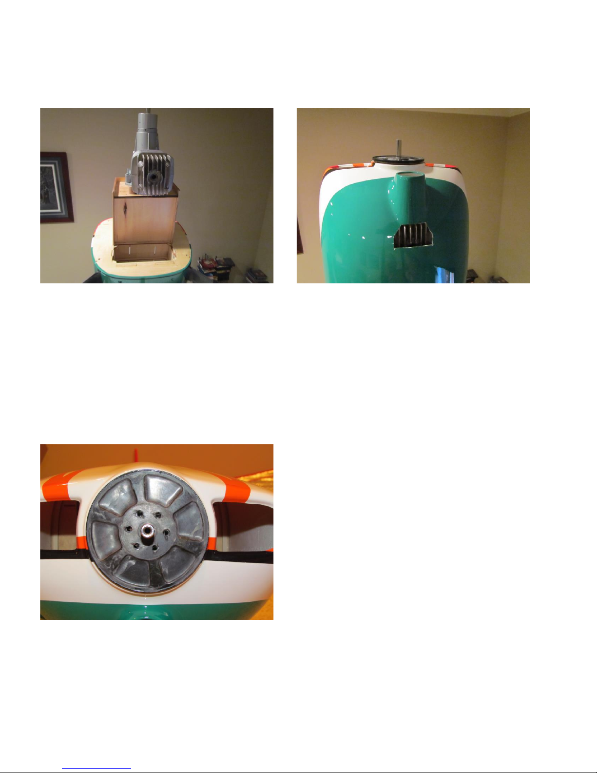
Support fuselage vertically on ladder (or similar).
You want the firewall to be horizontal. Place
engine on firewall. This is a 3W-55i with a metal
mounting plate. These standoffs are short oak
dowels. The mounting bolts with go through the
mounting plate, dowel and firewall.
Set cowl and spinner backplate in position. Cut
cowl as required to clear the head fins. Move the
engine until the spinner backplate lines up
properly with the cowl. Make sure cylinder
remains vertical.
Carefully remove spinner backplate and cowl.
Draw circles around the standoffs. Mounting
holes will be drilled in the center of the circles.
In this case, holes were drilled through the
dowels and firewall. Spinner backplate should
line up like this.
Installing engine other than DLE-55
Page 25
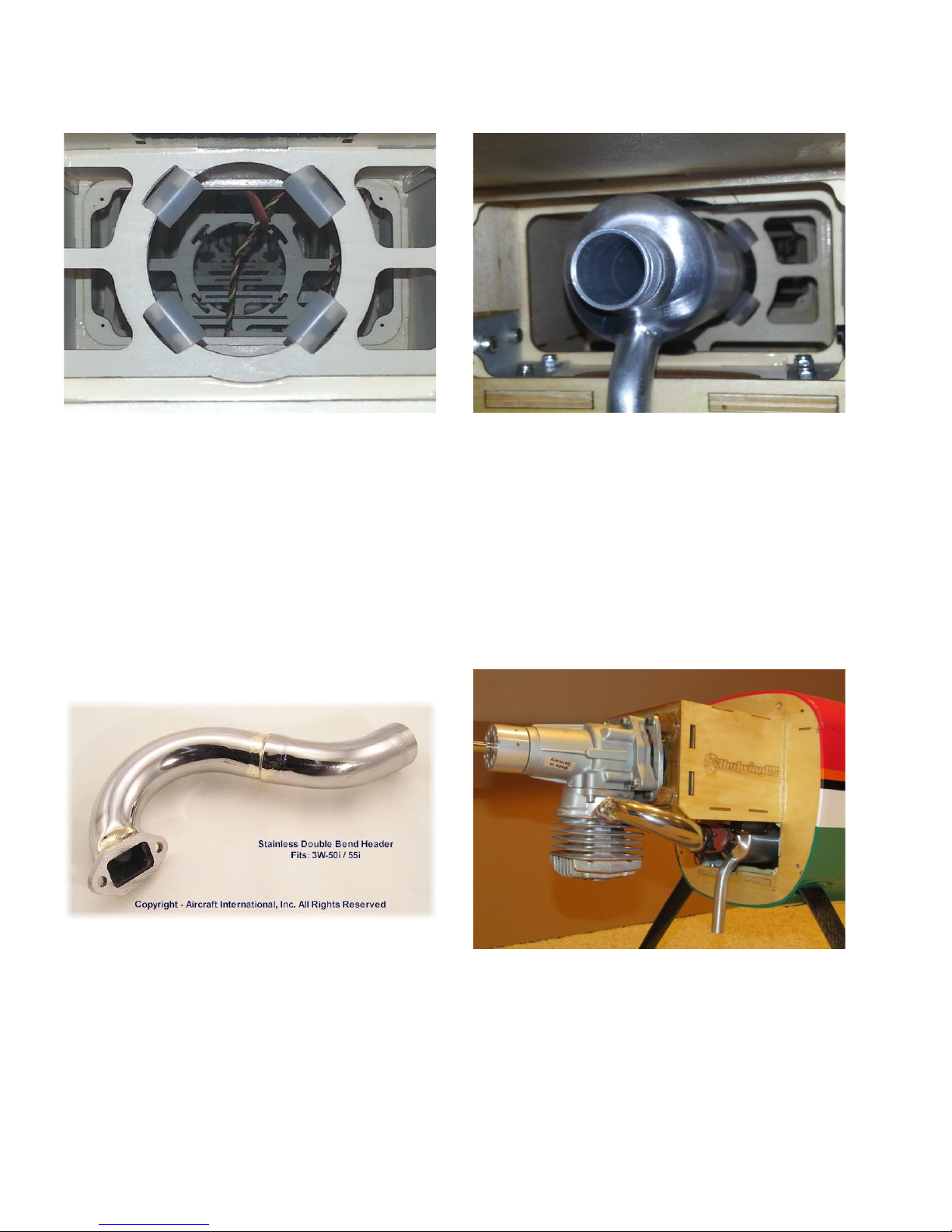
Canister muffler installation using 3W-55i and MTW canister
Rear of canister muffler needs to be shock
mounted. Install four pieces of silicone in pre-cut
mounts. Note – silicone is not included in kit.
Note how canister fits in the tunnel.
This header (available from Aircraft
International) seems to be custom made for the
3W-55i in this airplane.
Engine, header and canister installed. Note
coupler between header and canister. Also note a
small corner of the motorbox was cut off to clear
the header. This was cosmetic only and did not
affect strength at all.
Page 26
Prior to Flying
Surface
Throw
Expo
Aileron
25°
25%
Normal Flying
Elevator
20°
20%
Rudder
30°
20%
Aileron
40°
40%
3D Flying
Elevator
45°
40%
Rudder
50°
35%
Verify center of gravity is within the recommended range. Starting point is 25 to 30% (5” to 6”) back
from the leading edge at the root. Adjust to suit your personal flying style and preferences.
Control Throws:
Once again, these settings are a recommended starting point. Adjust to suit your flying style and
preferences.
Note: Futaba flyers should use negative values for exponential.
Balance the propeller. It is a good idea to balance it end to end and balance the hub. Redwing RC has
a video that demonstrates how to balance the propeller hub.
http://www.redwingrc.com/video/propvid.htm
Verify that all hardware (bolts, screws, wheel collars, etc.) are tight.
Check engine operation. It should run smoothly at all throttle settings. Do not attempt to fly unless
the engine is operating reliably.
Range check the model according to your radio manufacturer’s recommendations. Range check should
be performed both with and without the engine running. Do not attempt to fly if there is a large
reduction in range with the engine running until the cause for the discrepancy is determined.
Verify all batteries are fully charged.
Check that all control surfaces are centered. Trim levers on transmitter should be centered. All hinges
should operate smoothly, with no binding. They should be tight and not pull out.
Verify that all controls move in the proper direction.
Page 27

Engine positioning
There is a fairly simple way to determine or double check positioning of the engine prior to drilling any
holes. This method requires a way of holding the fuselage vertical while position is being checked.
One way to hold it vertical is by strapping the main landing gear to a step ladder. The method is
described below:
1. Hold the fuselage vertical by standing it on end and strapping the main landing gear to a step
ladder. Use padding as required to avoid denting or marring the finish of the fuselage.
2. Bolt the engine to all four standoffs.
3. Place the engine on the firewall in the approximate mounting location. Starting point is to center
the standoffs over the laser etched marks on the firewall.
4. Slide the cowl over the engine and onto the fuselage. The cowl ring will hold it in place. It doesn’t
have to be bolted on at this time. In order for this step to work, the initial hole for the engine head
has to have been cut into cowl already.
5. Place spinner backplate on engine.
6. Move engine until spinner backplate lines up with cowl. Make sure engine cylinder lines up
vertically with fuselage.
7. Carefully remove spinner backplate and cowl. Avoid moving engine.
8. Draw a circle on the firewall around the base of each standoff.
9. Remove engine.
10. Holes for mounting bolts should be drilled at the centers of the circles.
11. If installing a DLE-55, the centers of the circles you drew should match the laser etched locations on
the firewall.
 Loading...